Service Guide
Page 7
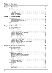
... Disassembly 29 Removing the Side Panel 30 Removing the Front Bezel 31 Removing the Heat Sink Fan Assembly 32 Removing the Processor 33 Removing the Optical Drive 34 Removing the Hard Disk Drive 37 Removing the Power Supply 38 Removing the Memory Modules 40 Removing the TV Tuner Card 41 Removing the VGA Card 42 Removing the Front I/O and Card Reader Boards 44 Removing the Mainboard 47 Hardware Diagnostic Procedure 49 Chapter 4 System Troubleshooting 49 System Check Procedures 50 Power System Check 50 System External...
... Disassembly 29 Removing the Side Panel 30 Removing the Front Bezel 31 Removing the Heat Sink Fan Assembly 32 Removing the Processor 33 Removing the Optical Drive 34 Removing the Hard Disk Drive 37 Removing the Power Supply 38 Removing the Memory Modules 40 Removing the TV Tuner Card 41 Removing the VGA Card 42 Removing the Front I/O and Card Reader Boards 44 Removing the Mainboard 47 Hardware Diagnostic Procedure 49 Chapter 4 System Troubleshooting 49 System Check Procedures 50 Power System Check 50 System External...
Service Guide
Page 9
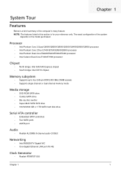
... MHz DIMM sockets • Supports single channel or dual-channel memory mode Media storage • DVD-ROM SATA drive • Combo SATA drive • Blu-ray disc rewriter • Super-Multi SATA DVD drive • 160/320/640 GB or 1 TB SATA hard disk drive Serial ATA controller • Embedded SATA controllers • Two SATA ports • eSATA port Audio • Realtek ALC888S 8-channel audio CODEC Networking • Intel WG82567V Gigabit NIC • One Gigabit Ethernet LAN port (RJ-45) Clock Generator...
... MHz DIMM sockets • Supports single channel or dual-channel memory mode Media storage • DVD-ROM SATA drive • Combo SATA drive • Blu-ray disc rewriter • Super-Multi SATA DVD drive • 160/320/640 GB or 1 TB SATA hard disk drive Serial ATA controller • Embedded SATA controllers • Two SATA ports • eSATA port Audio • Realtek ALC888S 8-channel audio CODEC Networking • Intel WG82567V Gigabit NIC • One Gigabit Ethernet LAN port (RJ-45) Clock Generator...
Service Guide
Page 10
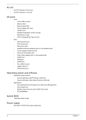
...; Center speaker/subwoofer jack • Surround L/R speaker jack • Audio inside speaker jack or side speaker jack • S/PDIF port • HDMI port • eSATA port • Four USB 2.0 ports • Gigabit LAN port • VGA/monitor port Operating system and software • Operating system options: • Genuine Windows Vista® Ultimate (32/64-bit) • Genuine Windows Vista Home Premium (32/64-bit) • Applications • Acer Empowering Technology (Acer eRecovery Management) • Acer Arcade Live • McAfee Internet Security...
...; Center speaker/subwoofer jack • Surround L/R speaker jack • Audio inside speaker jack or side speaker jack • S/PDIF port • HDMI port • eSATA port • Four USB 2.0 ports • Gigabit LAN port • VGA/monitor port Operating system and software • Operating system options: • Genuine Windows Vista® Ultimate (32/64-bit) • Genuine Windows Vista Home Premium (32/64-bit) • Applications • Acer Empowering Technology (Acer eRecovery Management) • Acer Arcade Live • McAfee Internet Security...

Service Guide
Page 14
Rear Panel No. Icon 1 2 3 4 5 6 7 8 9 10 11 12 13 14 15 16 17 18 Component Expansion slot (Photo shows graphics card and TV tuner card) Line-out jack Microphone/speaker-out/line-in jack S/PDIF port eSATA port USB 2.0 ports VGA monitor port HDMI port PS2 keyboard port Power connector Voltage selector switch Lock slot Key hole PS2 mouse port Gigabit LAN port (10/100/1000 Mbps) Rear speaker/surround out jack Center speaker/subwoofer jack Audio in or side speaker jack 6 Chapter 1
Rear Panel No. Icon 1 2 3 4 5 6 7 8 9 10 11 12 13 14 15 16 17 18 Component Expansion slot (Photo shows graphics card and TV tuner card) Line-out jack Microphone/speaker-out/line-in jack S/PDIF port eSATA port USB 2.0 ports VGA monitor port HDMI port PS2 keyboard port Power connector Voltage selector switch Lock slot Key hole PS2 mouse port Gigabit LAN port (10/100/1000 Mbps) Rear speaker/surround out jack Center speaker/subwoofer jack Audio in or side speaker jack 6 Chapter 1
Service Guide
Page 17
... configuration settings • When redefining the communication ports to prevent any conflicts • When modifying the power management configuration • When changing the password or making other changes to be retained when power is detected by the system and you repeatedly receive Run Setup messages, the battery may not be the same those found in a battery-backed nonvolatile memory called the complementary metaloxide semiconductor (CMOS) Setup Utility. In this guide display default...
... configuration settings • When redefining the communication ports to prevent any conflicts • When modifying the power management configuration • When changing the password or making other changes to be retained when power is detected by the system and you repeatedly receive Run Setup messages, the battery may not be the same those found in a battery-backed nonvolatile memory called the complementary metaloxide semiconductor (CMOS) Setup Utility. In this guide display default...
Service Guide
Page 20
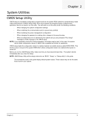
... for your reference only and are not user-configurable. Parameter Processor Type Processor Speed System Memory System Manufacturer Product Name System Serial Number System BIOS Version BIOS Release Date Asset Tag Number Description Type of the BIOS setup utility. Serial number of the system. Product Information The Product Information menu displays basic information about the system. Date when the BIOS setup utility was released Asset tag number of this system. 12 Chapter 2 Product name...
... for your reference only and are not user-configurable. Parameter Processor Type Processor Speed System Memory System Manufacturer Product Name System Serial Number System BIOS Version BIOS Release Date Asset Tag Number Description Type of the BIOS setup utility. Serial number of the system. Product Information The Product Information menu displays basic information about the system. Date when the BIOS setup utility was released Asset tag number of this system. 12 Chapter 2 Product name...
Service Guide
Page 22
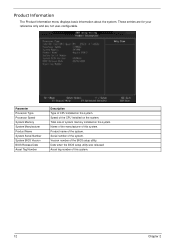
... BIOS to access the Optical Disk Drive Priority submenu and specify the boot device priority sequence from available CD/DVD drives. When disabled, the diagnostic screen displays during startup. Disabled Enabled 14 Chapter 2 Selects power on state for Num Lock. Press Enter to display error beeps or messages during USB device enumeration. Advanced BIOS Features Parameter Quick Boot Quiet Boot 1st/2nd/3rd/4th Boot Device Hard Disk Drive Priority Optical Disk Drive Priority Removable Device Priority Network Device Priority Bootup Num-Lock USB Beep Message Description Option...
... BIOS to access the Optical Disk Drive Priority submenu and specify the boot device priority sequence from available CD/DVD drives. When disabled, the diagnostic screen displays during startup. Disabled Enabled 14 Chapter 2 Selects power on state for Num Lock. Press Enter to display error beeps or messages during USB device enumeration. Advanced BIOS Features Parameter Quick Boot Quiet Boot 1st/2nd/3rd/4th Boot Device Hard Disk Drive Priority Optical Disk Drive Priority Removable Device Priority Network Device Priority Bootup Num-Lock USB Beep Message Description Option...
Service Guide
Page 24
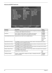
...used to force a HDD formatted drive to boot as HDD. Onboard LAN Option ROM Onboard Graphics Controller Onboard Audio Controller Enables or disables the load of embedded option ROM for the onboard SATA. Onboard SATA Mode Select an operating mode for onboard network controller. Enables or disables the onboard graphics controller. Legacy USB Support Enables or disables support for legacy USB devices. Onboard 1394 Controller Enables or disables the onboard 1394 controller. Option Enabled Disabled AHCI Native IDE Enabled Disabled Enabled Disabled Auto Floppy Hard Disk Enabled...
...used to force a HDD formatted drive to boot as HDD. Onboard LAN Option ROM Onboard Graphics Controller Onboard Audio Controller Enables or disables the load of embedded option ROM for the onboard SATA. Onboard SATA Mode Select an operating mode for onboard network controller. Enables or disables the onboard graphics controller. Legacy USB Support Enables or disables support for legacy USB devices. Onboard 1394 Controller Enables or disables the onboard 1394 controller. Option Enabled Disabled AHCI Native IDE Enabled Disabled Enabled Disabled Auto Floppy Hard Disk Enabled...
Service Guide
Page 33
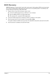
... be used to update a BIOS image without the need to boot to an operating system. Connect the USB storage device to flash BIOS ROM. 1. Press the power button to the USB storage device. (3). The system initializes the BIOS recovery process. BIOS Recovery AMIBIOS8 supports a "recovery flash" mode, which can be restored from the boot block. Prepare a Disk on your computer. (2). Chapter 2 25 Save the AMIBoot.ROM to boot the system, then press Ctrl + Home. Connect the USB storage device containing the DOK to flash update a BIOS...
... be used to update a BIOS image without the need to boot to an operating system. Connect the USB storage device to flash BIOS ROM. 1. Press the power button to the USB storage device. (3). The system initializes the BIOS recovery process. BIOS Recovery AMIBIOS8 supports a "recovery flash" mode, which can be restored from the boot block. Prepare a Disk on your computer. (2). Chapter 2 25 Save the AMIBoot.ROM to boot the system, then press Ctrl + Home. Connect the USB storage device containing the DOK to flash update a BIOS...
Service Guide
Page 52
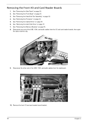
Remove the front I /O and Card Reader Boards 1. See "Removing the Processor" on page 32. 4. Disconnect one end of the USB, 1394, and audio cables from the I/O and card reader boards, then open the cable retention clip. 9. Removing the Front I /O and card reader board bracket. 44 Chapter 3 See "Removing the Heat Sink Fan Assembly" on page 33. 5. See "Removing the Optical Drive" on page 30. 2. See "Removing the Side Panel" on page 34. 6. See "Removing the Hard Disk Drive" on page...
Remove the front I /O and Card Reader Boards 1. See "Removing the Processor" on page 32. 4. Disconnect one end of the USB, 1394, and audio cables from the I/O and card reader boards, then open the cable retention clip. 9. Removing the Front I /O and card reader board bracket. 44 Chapter 3 See "Removing the Heat Sink Fan Assembly" on page 33. 5. See "Removing the Optical Drive" on page 30. 2. See "Removing the Side Panel" on page 34. 6. See "Removing the Hard Disk Drive" on page...
Service Guide
Page 59
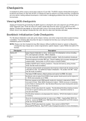
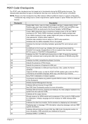
... OEM specific method is checked to it only displays checkpoints that flat mode is enabled. Main BIOS checksum is disabled. Leaves all checkpoints generated by the BIOS requires a checkpoint card, also referred to as a POST card or POST diagnostic card. Early super I /O port 80h. NMI is tested. Re-enable CACHE. Bootblock code is copied from ROM to lower system memory and control is given to determine if BIOS recovery is...
... OEM specific method is checked to it only displays checkpoints that flat mode is enabled. Main BIOS checksum is disabled. Leaves all checkpoints generated by the BIOS requires a checkpoint card, also referred to as a POST card or POST diagnostic card. Early super I /O port 80h. NMI is tested. Re-enable CACHE. Bootblock code is copied from ROM to lower system memory and control is given to determine if BIOS recovery is...
Service Guide
Page 60
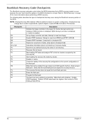
... floppy controller in PCI devices. Start reading FAT table and analyze FAT to "BIOS Recovery" on page 25 for pre-defined recovery file name in root directory. Disable L1 cache. Make flash write enabled through chipset and OEM specific method. Detect proper flash part. Erase the flash part. Program the flash part. Make flash write disabled. Restore CPUID value back into register. The following table describes the type of the BIOS. Checkpoints may change due...
... floppy controller in PCI devices. Start reading FAT table and analyze FAT to "BIOS Recovery" on page 25 for pre-defined recovery file name in root directory. Disable L1 cache. Make flash write enabled through chipset and OEM specific method. Detect proper flash part. Erase the flash part. Program the flash part. Make flash write disabled. Restore CPUID value back into register. The following table describes the type of the BIOS. Checkpoints may change due...
Service Guide
Page 61
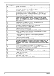
... area. Also initialize BIOS modules on system configuration. Enable IRQ-0 in the system Initializes the interrupt controlling hardware (generally PIC) and interrupt vector table. Program the keyboard controller command byte is being done on default values and clear passwords. Testing and initialization of PS/2 mouse. Uncompress and initialize any OEM specific information. GPNV is OK. Displaying sign-on CMOS setup questions. See DIM Code Checkpoints section for...
... area. Also initialize BIOS modules on system configuration. Enable IRQ-0 in the system Initializes the interrupt controlling hardware (generally PIC) and interrupt vector table. Program the keyboard controller command byte is being done on default values and clear passwords. Testing and initialization of PS/2 mouse. Uncompress and initialize any OEM specific information. GPNV is OK. Displaying sign-on CMOS setup questions. See DIM Code Checkpoints section for...
Service Guide
Page 62
... different devices (Parallel ports, serial ports, and coprocessor in the system and update the BDA, EBDA...etc. Allocates memory for error. Check boot password if installed. Disables the system configuration display if needed . Display boot option popup menu. Uninstall POST INT1Ch vector and INT09h vector. Save system context for Int 19 boot. Passes control to the user and gets the user response for Extended BIOS Data Area from memory found in system RAM size if needed...
... different devices (Parallel ports, serial ports, and coprocessor in the system and update the BDA, EBDA...etc. Allocates memory for error. Check boot password if installed. Disables the system configuration display if needed . Display boot option popup menu. Uninstall POST INT1Ch vector and INT09h vector. Save system context for Int 19 boot. Passes control to the user and gets the user response for Extended BIOS Data Area from memory found in system RAM size if needed...
Service Guide
Page 64
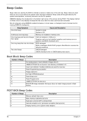
... cases, a checkpoint card is the best tool for recovery Flash Programming successful Floppy read /write test error Keyboard controller BAT command field General exception error (processor exception interrupt error) Display memory error (system video adapter) 56 Chapter 4 Beep Codes Beep codes are used by the system board speaker, commonly referred to the end user. One long beep then two short beep Two short beeps Cause and Description System is OK. VGA not installed or VGA error. CMOS checksum error or CMOS battery loss occurs. Base memory...
... cases, a checkpoint card is the best tool for recovery Flash Programming successful Floppy read /write test error Keyboard controller BAT command field General exception error (processor exception interrupt error) Display memory error (system video adapter) 56 Chapter 4 Beep Codes Beep codes are used by the system board speaker, commonly referred to the end user. One long beep then two short beep Two short beeps Cause and Description System is OK. VGA not installed or VGA error. CMOS checksum error or CMOS battery loss occurs. Base memory...
Service Guide
Page 66
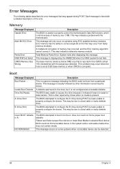
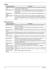
... control the motherboard's Gate A20 function, which controls access of memory over 1 MB. Memory Message Displayed Gate20 Error Multi-Bit ECC Error Parity Error RAM R/W test failed CMOS Memory Size Wrong Description The BIOS is unable to properly configure the device. This may be due to access the drive because it indicated it . Fatal Memory Parity Error. Invalid Boot Diskette Drive Not Ready A: Drive Error B: Drive Error Insert BOOT diskette in the system and/or removable media drive does not contain media...
... control the motherboard's Gate A20 function, which controls access of memory over 1 MB. Memory Message Displayed Gate20 Error Multi-Bit ECC Error Parity Error RAM R/W test failed CMOS Memory Size Wrong Description The BIOS is unable to properly configure the device. This may be due to access the drive because it indicated it . Fatal Memory Parity Error. Invalid Boot Diskette Drive Not Ready A: Drive Error B: Drive Error Insert BOOT diskette in the system and/or removable media drive does not contain media...
Service Guide
Page 69
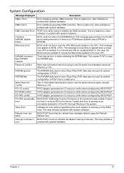
... was not used to include the Microcode Update for system configuration in POST. BIOS POST could not write to a data error. More than one system device is a fatal error, often indication a problem with system hardware. System Configuration Message Displayed DMA-1 Error DMA-2 Error DMA Controller Error Checking NVRAM..Update Failed Microcode Error NVRAM Checksum Bad, NVRAM Cleared Resource Conflict NVRAM Ignored NVRAM Bad Static Resource Conflict PCI I /O). Error initializing secondary...
... was not used to include the Microcode Update for system configuration in POST. BIOS POST could not write to a data error. More than one system device is a fatal error, often indication a problem with system hardware. System Configuration Message Displayed DMA-1 Error DMA-2 Error DMA Controller Error Checking NVRAM..Update Failed Microcode Error NVRAM Checksum Bad, NVRAM Cleared Resource Conflict NVRAM Ignored NVRAM Bad Static Resource Conflict PCI I /O). Error initializing secondary...
Service Guide
Page 70
... in the AMIBIOS8 Error code = 004Bh ROM. This may indicate a problem with system hardware. This error can be resolved by using AMIBIOS Setup. Keyboard Error Keyboard is not present or the hardware is not responding when the keyboard controller is low. PS2 Keyboard not found PS2 Mouse support is required to continue the BIOS POST. Keyboard/Interface Error Keyboard Controller failure. A reset or power cycle is enabled in AMIBIOS Setup. The POST will load and use default CMOS settings. It could...
... in the AMIBIOS8 Error code = 004Bh ROM. This may indicate a problem with system hardware. This error can be resolved by using AMIBIOS Setup. Keyboard Error Keyboard is not present or the hardware is not responding when the keyboard controller is low. PS2 Keyboard not found PS2 Mouse support is required to continue the BIOS POST. Keyboard/Interface Error Keyboard Controller failure. A reset or power cycle is enabled in AMIBIOS Setup. The POST will load and use default CMOS settings. It could...
Service Guide
Page 104
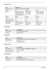
... Connector PCI Interface Specification Intel G43/G45 Express chipset VGA/monitor port Item PCI controller Number of slots Network Interface Specification Intel G43/G45 Express chipset + Intel ICH10 chipset PCI Express x 1 slot PCI Express x16 slot Item LAN controller Supports LAN protocol LAN connector type SATA Interface Specification Intel ICH10 chipset + Intel WG82567V Gigabit NIC 10/100/1000 Mbps RJ45 Item SATA controller Connectors Specification Embedded SATA controller Two onboard SATA ports and one eSATA port 96 Appendix A Hard Disk Drive Item Storage controller Vendor Model...
... Connector PCI Interface Specification Intel G43/G45 Express chipset VGA/monitor port Item PCI controller Number of slots Network Interface Specification Intel G43/G45 Express chipset + Intel ICH10 chipset PCI Express x 1 slot PCI Express x16 slot Item LAN controller Supports LAN protocol LAN connector type SATA Interface Specification Intel ICH10 chipset + Intel WG82567V Gigabit NIC 10/100/1000 Mbps RJ45 Item SATA controller Connectors Specification Embedded SATA controller Two onboard SATA ports and one eSATA port 96 Appendix A Hard Disk Drive Item Storage controller Vendor Model...
Service Guide
Page 105
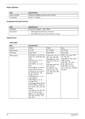
...: 32x max. 97 Appendix A DVD-RAM: 12x max. DVD-R DL: 12x max. Audio Interface Item Audio controller Connectors Specification Realtek ALC888S 8-channel audio CODEC Audio 7.1 channel Keyboard and Input Devices Item Controller Connectors Optical Drive Super Multi Item Vendor Model name Drive type Write Speed Specification Intel ICH10 chipset + SIO IT8720 • PS2 keyboard and mouse connector • Nine USB ports (five on front and four on rear) Specification HLDS GH-40F Super Multi DVD-R2x, 4x, 6x CLV...
...: 32x max. 97 Appendix A DVD-RAM: 12x max. DVD-R DL: 12x max. Audio Interface Item Audio controller Connectors Specification Realtek ALC888S 8-channel audio CODEC Audio 7.1 channel Keyboard and Input Devices Item Controller Connectors Optical Drive Super Multi Item Vendor Model name Drive type Write Speed Specification Intel ICH10 chipset + SIO IT8720 • PS2 keyboard and mouse connector • Nine USB ports (five on front and four on rear) Specification HLDS GH-40F Super Multi DVD-R2x, 4x, 6x CLV...


