Service Guide
Page 7
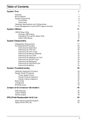
... 39 System Check Procedures 40 Power System Check 40 System External Inspection 40 System Internal Inspection 40 Beep Codes 41 Checkpoints 42 BIOS Recovery 44 Jumper and Connector Information 45 M/B Placement 45 Jumper Setting 46 Setting Jumper 46 FRU (Field Replaceable Unit) List 53 Aspire R3700 Exploded Diagram 54 Aspire R3700 FRU List 55 vii
... 39 System Check Procedures 40 Power System Check 40 System External Inspection 40 System Internal Inspection 40 Beep Codes 41 Checkpoints 42 BIOS Recovery 44 Jumper and Connector Information 45 M/B Placement 45 Jumper Setting 46 Setting Jumper 46 FRU (Field Replaceable Unit) List 53 Aspire R3700 Exploded Diagram 54 Aspire R3700 FRU List 55 vii

Service Guide
Page 8
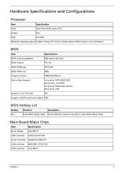
...; 1GB to 4GB Max memory support(follow Intel Spec.) • Design Criteria: • Should follow Pine Trail-D platform design guide • Should meet Pine Trail-D BIOS Specification Chapter 1 1
...; 1GB to 4GB Max memory support(follow Intel Spec.) • Design Criteria: • Should follow Pine Trail-D platform design guide • Should meet Pine Trail-D BIOS Specification Chapter 1 1
Service Guide
Page 9
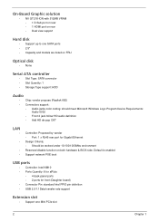
On-Board Graphic solution • NV GT218-ION with 512MB VRAM • 1 D-Sub port on rear • 1 HDMI port on both hardware & BIOS side. Default is enabled Support network PXE boot USB ports • Controller: Intel NM10 • Ports Quantity: 6 for aPluto • 4 back panel ports • 2 ports ...
On-Board Graphic solution • NV GT218-ION with 512MB VRAM • 1 D-Sub port on rear • 1 HDMI port on both hardware & BIOS side. Default is enabled Support network PXE boot USB ports • Controller: Intel NM10 • Ports Quantity: 6 for aPluto • 4 back panel ports • 2 ports ...
Service Guide
Page 10
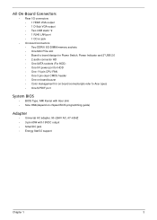
... header • One on board buzzer • Color management for on board connecter(pls refer to Acer spec) • One S/PDIF port System BIOS • BIOS Type: AMI Kernel with Acer skin • Size: 8Mb(depend on chipset BIOS programming guide) Adapter • Universal AC adapter, 90~264V AC, 47~63HZ • 3-pin 65W with...
... header • One on board buzzer • Color management for on board connecter(pls refer to Acer spec) • One S/PDIF port System BIOS • BIOS Type: AMI Kernel with Acer skin • Size: 8Mb(depend on chipset BIOS programming guide) Adapter • Universal AC adapter, 90~264V AC, 47~63HZ • 3-pin 65W with...
Service Guide
Page 14
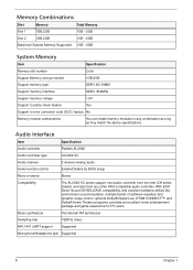
... FSB 800 MHz Minimum operating speed 0 MHz (If Stop CPU Clock in Sleep State in BIOS Setup is set to Enabled.) BIOS Item Specification BIOS code programmer AMI Kernel with Acer BIOS version P01-A0 BIOS ROM type SPI ROM BIOS ROM size 8MB Support protocol SMBIOS(DMI)2.6 Device Boot Support 1st priority: SATA HDD/SDD 2nd...
... FSB 800 MHz Minimum operating speed 0 MHz (If Stop CPU Clock in Sleep State in BIOS Setup is set to Enabled.) BIOS Item Specification BIOS code programmer AMI Kernel with Acer BIOS version P01-A0 BIOS ROM type SPI ROM BIOS ROM size 8MB Support protocol SMBIOS(DMI)2.6 Device Boot Support 1st priority: SATA HDD/SDD 2nd...
Service Guide
Page 15
... 8 Chapter 1 Audio Interface Item Specification Audio controller Realtek ALC662 Audio controller type ALC662-VC Audio channel 2 channel analog audio Audio function control Enable/Disable by BIOS setup Mono or stereo Stereo Compatibility The ALC662-VC series support host audio controller from the Intel ICH series chipset, and also from any combination...
... 8 Chapter 1 Audio Interface Item Specification Audio controller Realtek ALC662 Audio controller type ALC662-VC Audio channel 2 channel analog audio Audio function control Enable/Disable by BIOS setup Mono or stereo Stereo Compatibility The ALC662-VC series support host audio controller from the Intel ICH series chipset, and also from any combination...
Service Guide
Page 18
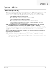
... 2 System Utilities CMOS Setup Utility CMOS setup is turned off. In this guide display default system values. This memory area is no need to as "BIOS", "Setup", or "Setup utility" in CMOS. Chapter 2 12 These values may be retained when power is a hardware configuration program built into the system ROM, called...
... 2 System Utilities CMOS Setup Utility CMOS setup is turned off. In this guide display default system values. This memory area is no need to as "BIOS", "Setup", or "Setup utility" in CMOS. Chapter 2 12 These values may be retained when power is a hardware configuration program built into the system ROM, called...
Service Guide
Page 20
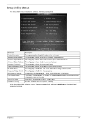
... Standard CMOS Features Advanced Chipset Features Advanced Chipset Features Integrated Peripherals Power Management Setup PC Health Status Frequency/Voltage Control BIOS Security Features Load Default Setting Save & Exit Setup Exit Without Saving Description This page shows the relevant information of Green...Chapter 2 14 Setup Utility Menus The Setup Main menu includes the following each of the menu screenshots, settings in standard compatible BIOS This setup page includes all the items of Award special enhanced features This setup page includes all advanced chipset features This setup...
... Standard CMOS Features Advanced Chipset Features Advanced Chipset Features Integrated Peripherals Power Management Setup PC Health Status Frequency/Voltage Control BIOS Security Features Load Default Setting Save & Exit Setup Exit Without Saving Description This page shows the relevant information of Green...Chapter 2 14 Setup Utility Menus The Setup Main menu includes the following each of the menu screenshots, settings in standard compatible BIOS This setup page includes all the items of Award special enhanced features This setup page includes all advanced chipset features This setup...
Service Guide
Page 21
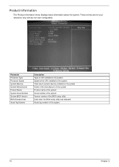
... Asset Tag Number Description Type of the CPU installed on the system. Speed of CPU installed on the system. Serial number of the BIOS setup utility. Version number of the system. Total size of the system. Name of the manufacturer of this system. These entries are ...for your reference only and are not user-configurable. Product name of system memory installed on the system. Date when the BIOS setup utility was released Asset tag number of this system. 15 Chapter 2 Product Information The Product Information menu displays basic information about the system...
... Asset Tag Number Description Type of the CPU installed on the system. Speed of CPU installed on the system. Serial number of the BIOS setup utility. Version number of the system. Total size of the system. Name of the manufacturer of this system. These entries are ...for your reference only and are not user-configurable. Product name of system memory installed on the system. Date when the BIOS setup utility was released Asset tag number of this system. 15 Chapter 2 Product Information The Product Information menu displays basic information about the system...
Service Guide
Page 23
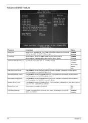
... error beeps or messages during startup. Enabled Disabled Specifies the boot order from available network drives. On Off Enables or disables BIOS to access the Network Drive Priority submenu and specify the boot device priority sequence from the available devices. Hard Disk CD^DVD... to boot the computer by shortening Enabled or skipping certain standard booting process. Disabled When enabled, the BIOS splash screen displays during USB device enumeration. Advanced BIOS Feature Parameter Quick Boot Quiet Boot 1st/2nd/3rd/4th Boot Device Hard Disk Drive Priority Optical Disk ...
... error beeps or messages during startup. Enabled Disabled Specifies the boot order from available network drives. On Off Enables or disables BIOS to access the Network Drive Priority submenu and specify the boot device priority sequence from the available devices. Hard Disk CD^DVD... to boot the computer by shortening Enabled or skipping certain standard booting process. Disabled When enabled, the BIOS splash screen displays during USB device enumeration. Advanced BIOS Feature Parameter Quick Boot Quiet Boot 1st/2nd/3rd/4th Boot Device Hard Disk Drive Priority Optical Disk ...
Service Guide
Page 29
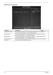
..., Not Installed displays. If the password has been installed,Installed displays. If not, Not Installed displays. This item indicates whether a HDD password has been set . BIOS Security Features Parameter Supervisor Password User Password HDD Password Change Supervisor Password Description Option This item indicates whether a supervisor password has been set . If the...
..., Not Installed displays. If the password has been installed,Installed displays. If not, Not Installed displays. This item indicates whether a HDD password has been set . BIOS Security Features Parameter Supervisor Password User Password HDD Password Change Supervisor Password Description Option This item indicates whether a supervisor password has been set . If the...
Service Guide
Page 30
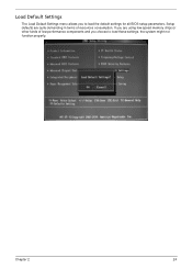
If you are quite demanding in terms of low-performance components and you to load these settings, the system might not function properly. Chapter 2 24 Load Default Settings The Load Default Settings menu allows you choose to load the default settings for all BIOS setup parameters. Setup defaults are using low-speed memory chips or other kinds of resources consumption.
If you are quite demanding in terms of low-performance components and you to load these settings, the system might not function properly. Chapter 2 24 Load Default Settings The Load Default Settings menu allows you choose to load the default settings for all BIOS setup parameters. Setup defaults are using low-speed memory chips or other kinds of resources consumption.
Service Guide
Page 46
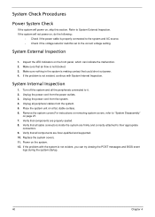
.... 9. Verify that all the peripherals connected to the correct voltage setting. Verify that components are Acer-qualified and supported. 10. Inspect the LED indicators on the front panel, which can try viewing the POST messages and BIOS event logs during the system startup. 40 Chapter 4 System Internal Inspection 1. Replace the system covers...
.... 9. Verify that all the peripherals connected to the correct voltage setting. Verify that components are Acer-qualified and supported. 10. Inspect the LED indicators on the front panel, which can try viewing the POST messages and BIOS event logs during the system startup. 40 Chapter 4 System Internal Inspection 1. Replace the system covers...
Service Guide
Page 47
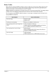
...the PC speaker. Beep codes are used when an error occurs before the system video has been initialized. Beep codes will be generated by the BIOS to indicate a serious or fatal error to execute the default procedures. AMIBIOS displays the checkpoints in the bottom right corner of the screen during... POST. Not all computers using AMIBIOS enable this feature. CMOS checksum error or CMOS battery loss occurs. In most cases, a checkpoint card is damaged, BIOS POST jumps to Boot Block to the end user. One long beep then two short beep Two short beeps Cause and Description System is limited...
...the PC speaker. Beep codes are used when an error occurs before the system video has been initialized. Beep codes will be generated by the BIOS to indicate a serious or fatal error to execute the default procedures. AMIBIOS displays the checkpoints in the bottom right corner of the screen during... POST. Not all computers using AMIBIOS enable this feature. CMOS checksum error or CMOS battery loss occurs. In most cases, a checkpoint card is damaged, BIOS POST jumps to Boot Block to the end user. One long beep then two short beep Two short beeps Cause and Description System is limited...
Service Guide
Page 48
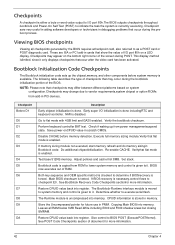
... determine if BIOSrecovery is tested. Perform keyboard controller BAT test. Disable CACHE before system memory is uncompressed into register. Main BIOS checksum is forced. The Bootblock-Runtime interface module is moved to system memory and control is given to it only displays ... CPUID value back into memory. These are ISA or PCI add-in memory. See POST Code Checkpoints section of RAM. Give control to BIOS POST (ExecutePOSTKernel). This display method islimited, since it . Checkpoints A checkpoint is either a byte or word value output to I /O initialization...
... determine if BIOSrecovery is tested. Perform keyboard controller BAT test. Disable CACHE before system memory is uncompressed into register. Main BIOS checksum is forced. The Bootblock-Runtime interface module is moved to system memory and control is given to it only displays ... CPUID value back into memory. These are ISA or PCI add-in memory. See POST Code Checkpoints section of RAM. Give control to BIOS POST (ExecutePOSTKernel). This display method islimited, since it . Checkpoints A checkpoint is either a byte or word value output to I /O initialization...
Service Guide
Page 49
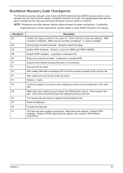
... found flash part size equals the recovery file size. Check the validity of the recovery file configuration to the current configuration of the BIOS. Disable ATAPI hardware. Give control to vendor requirements, system chipset or option ROMs from add-in PCI devices. Chapter 4 43 Some...that the found . Bootblock Recovery Code Checkpoints The Bootblock recovery code gets control when the BIOS determines that a BIOS recovery needs to occur because the user has forced the update or the BIOS checksum is enabled. The following table describes the type of checkpoints that may differ between...
... found flash part size equals the recovery file size. Check the validity of the recovery file configuration to the current configuration of the BIOS. Disable ATAPI hardware. Give control to vendor requirements, system chipset or option ROMs from add-in PCI devices. Chapter 4 43 Some...that the found . Bootblock Recovery Code Checkpoints The Bootblock recovery code gets control when the BIOS determines that a BIOS recovery needs to occur because the user has forced the update or the BIOS checksum is enabled. The following table describes the type of checkpoints that may differ between...
Service Guide
Page 50
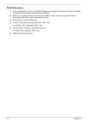
AMIBIOS Recovery is finished. 44 Chapter 4 Copy the target BIOS rom file to enter BIOS Setup. 4. Press "Del" Key to a USB disk. Wait for about 3 minutes the system will be done. Choose " Load Default Settings " and press " Enter " key. 4-1.Choose " ...OK " and press "Enter " key. 5. Choose "Save & Exit Setup " and press "Enter" key. 5-1.Choose " OK " and press "Enter " key. 6. Rename the target BIOS to "amiboot.rom".Plug the USB disk to computer that you want to recovery the system...
AMIBIOS Recovery is finished. 44 Chapter 4 Copy the target BIOS rom file to enter BIOS Setup. 4. Press "Del" Key to a USB disk. Wait for about 3 minutes the system will be done. Choose " Load Default Settings " and press " Enter " key. 4-1.Choose " ...OK " and press "Enter " key. 5. Choose "Save & Exit Setup " and press "Enter" key. 5-1.Choose " OK " and press "Enter " key. 6. Rename the target BIOS to "amiboot.rom".Plug the USB disk to computer that you want to recovery the system...


