Service Guide
Page 7
... D/B 33 Removing the Wireless Lan Card 34 Removing the S/PDIF Cover 35 Removing the Mainboard 36 Removing the Hard Disk Drive 37 Removing the Battery 38 System Troubleshooting 39 Hardware Diagnostic Procedure 39 System Check Procedures 40 Power System Check 40 System External Inspection 40 System Internal Inspection 40 Beep Codes 41 Checkpoints 42 BIOS Recovery 44 Jumper and Connector Information 45 M/B Placement 45 Jumper Setting 46 Setting Jumper 46 FRU (Field Replaceable Unit) List 53 Aspire R3700 Exploded Diagram 54 Aspire R3700 FRU List 55 vii
... D/B 33 Removing the Wireless Lan Card 34 Removing the S/PDIF Cover 35 Removing the Mainboard 36 Removing the Hard Disk Drive 37 Removing the Battery 38 System Troubleshooting 39 Hardware Diagnostic Procedure 39 System Check Procedures 40 Power System Check 40 System External Inspection 40 System Internal Inspection 40 Beep Codes 41 Checkpoints 42 BIOS Recovery 44 Jumper and Connector Information 45 M/B Placement 45 Jumper Setting 46 Setting Jumper 46 FRU (Field Replaceable Unit) List 53 Aspire R3700 Exploded Diagram 54 Aspire R3700 FRU List 55 vii
Service Guide
Page 9
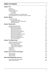
...; 1 HDMI port on both hardware & BIOS side. Default is enabled Support network PXE boot USB ports • Controller: Intel NM10 • Ports Quantity: 6 for aPluto • 4 back panel ports • 2 ports for front (Daughter board) • Connector Pin: standard Intel FPIO pin definition • USB 2.0/1.1Data transfer rate support Extension slot • Support one SATA ports • 2.5" • Capacity and models are listed on FRU Optical disk • None Serial ATA controller • Slot Type: SATA connector • Slot Quantity: 1 • Storage Type support: HDD Audio...
...; 1 HDMI port on both hardware & BIOS side. Default is enabled Support network PXE boot USB ports • Controller: Intel NM10 • Ports Quantity: 6 for aPluto • 4 back panel ports • 2 ports for front (Daughter board) • Connector Pin: standard Intel FPIO pin definition • USB 2.0/1.1Data transfer rate support Extension slot • Support one SATA ports • 2.5" • Capacity and models are listed on FRU Optical disk • None Serial ATA controller • Slot Type: SATA connector • Slot Quantity: 1 • Storage Type support: HDD Audio...
Service Guide
Page 10
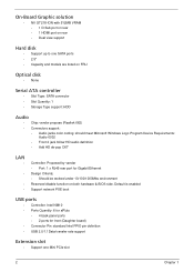
... PCIe slot • Board to board design for Power Switch, Power Indicator and 2*USB 2.0 • 2 audio connector HD • One SATA sockets (For HDD) • One 5V power port for HDD • One 1*4 pin CPU FAN • One 3 pin clear CMOS header • One on board buzzer • Color management for on board connecter(pls refer to Acer spec) • One S/PDIF port System BIOS • BIOS Type: AMI Kernel with Acer skin • Size: 8Mb(depend on chipset BIOS programming guide) Adapter •...
... PCIe slot • Board to board design for Power Switch, Power Indicator and 2*USB 2.0 • 2 audio connector HD • One SATA sockets (For HDD) • One 5V power port for HDD • One 1*4 pin CPU FAN • One 3 pin clear CMOS header • One on board buzzer • Color management for on board connecter(pls refer to Acer spec) • One S/PDIF port System BIOS • BIOS Type: AMI Kernel with Acer skin • Size: 8Mb(depend on chipset BIOS programming guide) Adapter •...
Service Guide
Page 14
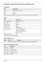
... NM10 VGA controller Nvidia GT218-ION Audio controller Realtek ALC662-VC LAN controller REALTEK_RTL8111E USB controller Intel NM10 Chapter 1 7 Hardware Specifications and Configurations Processor Item Specification Type Intel Atom D500 series CPU Socket Non FSB 800 MHz Minimum operating speed 0 MHz (If Stop CPU Clock in Sleep State in BIOS Setup is set to Enabled.) BIOS Item Specification BIOS code programmer AMI Kernel with Acer BIOS version P01-A0 BIOS ROM type SPI ROM BIOS ROM size 8MB Support protocol SMBIOS(DMI)2.6 Device Boot Support 1st priority: SATA HDD...
... NM10 VGA controller Nvidia GT218-ION Audio controller Realtek ALC662-VC LAN controller REALTEK_RTL8111E USB controller Intel NM10 Chapter 1 7 Hardware Specifications and Configurations Processor Item Specification Type Intel Atom D500 series CPU Socket Non FSB 800 MHz Minimum operating speed 0 MHz (If Stop CPU Clock in Sleep State in BIOS Setup is set to Enabled.) BIOS Item Specification BIOS code programmer AMI Kernel with Acer BIOS version P01-A0 BIOS ROM type SPI ROM BIOS ROM size 8MB Support protocol SMBIOS(DMI)2.6 Device Boot Support 1st priority: SATA HDD...
Service Guide
Page 15
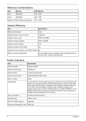
... Memory Item Specification Memory slot number 2 slot Support Memory size per socket 1GB,2GB Support memory type DDR3 SO-DIMM Support memory interface DDR3 800MHz Support memory voltage 1.5V Support to parity check feature Yes Support to error correction code (ECC) feature No Memory module combinations You can install memory modules in any other HDA compatible audio controller. Audio Interface Item Specification Audio controller Realtek ALC662 Audio controller type ALC662-VC Audio channel 2 channel analog audio Audio function control Enable/Disable by BIOS setup...
... Memory Item Specification Memory slot number 2 slot Support Memory size per socket 1GB,2GB Support memory type DDR3 SO-DIMM Support memory interface DDR3 800MHz Support memory voltage 1.5V Support to parity check feature Yes Support to error correction code (ECC) feature No Memory module combinations You can install memory modules in any other HDA compatible audio controller. Audio Interface Item Specification Audio controller Realtek ALC662 Audio controller type ALC662-VC Audio channel 2 channel analog audio Audio function control Enable/Disable by BIOS setup...
Service Guide
Page 16
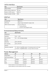
...less than 10 second S5 V N/A Disabled Disabled Disabled Chapter 1 9 SATA Interface Item SATA controller SATA controller resident bus Number of SATA channel Support bootable CD-ROM Specification Intel NM10 PCI bus SATA X 1 YES USB Port Item Universal HCI USB Class USB Connectors Quantity Specification USB 2.0/1.1 Support legacy keyboard for legacy mode 6 port for vPluto_D3 • 4 back panel ports • 2 ports for front (Daughter board) Environmental Requirements Item Specification Temperature Operating +5°C ~ +35°C Non-operating -20 ~ +60°C (Storage package...
...less than 10 second S5 V N/A Disabled Disabled Disabled Chapter 1 9 SATA Interface Item SATA controller SATA controller resident bus Number of SATA channel Support bootable CD-ROM Specification Intel NM10 PCI bus SATA X 1 YES USB Port Item Universal HCI USB Class USB Connectors Quantity Specification USB 2.0/1.1 Support legacy keyboard for legacy mode 6 port for vPluto_D3 • 4 back panel ports • 2 ports for front (Daughter board) Environmental Requirements Item Specification Temperature Operating +5°C ~ +35°C Non-operating -20 ~ +60°C (Storage package...
Service Guide
Page 17
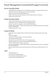
... mode • Return to control the VESA DPMS monitor. • Resume method:device activated (keyboard for DOS, keyboard &mouse for ACPI mode. On board device configuration support. 10 Chapter 1 Global Standby Mode • Global power management timer(2-120minutes,time step=10minute). • Hard disk drive goes into power saving mode. • Resume method: Resume to original state by pushing external switch button,modem ring inand USB keyboard for Windows. • Resume recovery time 3-5sec. On board device power management support. ACPI ACPI specification...
... mode • Return to control the VESA DPMS monitor. • Resume method:device activated (keyboard for DOS, keyboard &mouse for ACPI mode. On board device configuration support. 10 Chapter 1 Global Standby Mode • Global power management timer(2-120minutes,time step=10minute). • Hard disk drive goes into power saving mode. • Resume method: Resume to original state by pushing external switch button,modem ring inand USB keyboard for Windows. • Resume recovery time 3-5sec. On board device power management support. ACPI ACPI specification...
Service Guide
Page 18
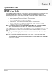
... communication ports to prevent any conflicts • When modifying the power management configuration • When changing the password or making other changes to the security setup • When a configuration error is detected by the system and you are already properly configured and optimized, there is no need to run the CMOS Setup Utility, make changes to as "BIOS", "Setup", or "Setup utility" in a battery-backed nonvolatile memory called the complementary metaloxide semiconductor (CMOS) Setup Utility. CMOS setup loads the configuration values...
... communication ports to prevent any conflicts • When modifying the power management configuration • When changing the password or making other changes to the security setup • When a configuration error is detected by the system and you are already properly configured and optimized, there is no need to run the CMOS Setup Utility, make changes to as "BIOS", "Setup", or "Setup utility" in a battery-backed nonvolatile memory called the complementary metaloxide semiconductor (CMOS) Setup Utility. CMOS setup loads the configuration values...
Service Guide
Page 20
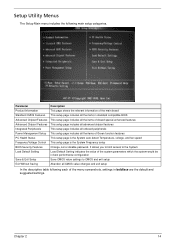
... Temperature, voltage, and fan speed This setup page is the System Frequency setup Change, set or disable password. Parameter Product Information Standard CMOS Features Advanced Chipset Features Advanced Chipset Features Integrated Peripherals Power Management Setup PC Health Status Frequency/Voltage Control BIOS Security Features Load Default Setting Save & Exit Setup Exit Without Saving Description This page shows the relevant information of the main board This setup page includes all...
... Temperature, voltage, and fan speed This setup page is the System Frequency setup Change, set or disable password. Parameter Product Information Standard CMOS Features Advanced Chipset Features Advanced Chipset Features Integrated Peripherals Power Management Setup PC Health Status Frequency/Voltage Control BIOS Security Features Load Default Setting Save & Exit Setup Exit Without Saving Description This page shows the relevant information of the main board This setup page includes all...
Service Guide
Page 21
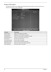
... when the BIOS setup utility was released Asset tag number of CPU installed on the system. Product Information The Product Information menu displays basic information about the system. These entries are for your reference only and are not user-configurable. Parameter Processor Type Processor Speed System Memory System Manufacturer Product Name System Serial Number System BIOS Version BIOS Release Date Asset Tag Number Description Type of this system. Serial number of the BIOS setup utility. Total...
... when the BIOS setup utility was released Asset tag number of CPU installed on the system. Product Information The Product Information menu displays basic information about the system. These entries are for your reference only and are not user-configurable. Parameter Processor Type Processor Speed System Memory System Manufacturer Product Name System Serial Number System BIOS Version BIOS Release Date Asset Tag Number Description Type of this system. Serial number of the BIOS setup utility. Total...
Service Guide
Page 22
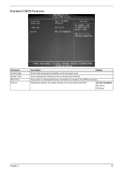
Standard CMOS Features Parameter System Date System Time AHCI Port Halt On Description Option Set the date following the hour-minute-second format. Determines whether the system will stop for an error during the POST. Set the system time following the weekday-month-day-year format. All, But Keyboard No Errors All Errors Chapter 2 16 Press Enter to view detailed device information connected to the SATA connectors.
Standard CMOS Features Parameter System Date System Time AHCI Port Halt On Description Option Set the date following the hour-minute-second format. Determines whether the system will stop for an error during the POST. Set the system time following the weekday-month-day-year format. All, But Keyboard No Errors All Errors Chapter 2 16 Press Enter to view detailed device information connected to the SATA connectors.
Service Guide
Page 23
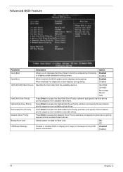
... Disabled Enabled 17 Chapter 2 Press Enter to access the Network Drive Priority submenu and specify the boot device priority sequence from the available devices. Advanced BIOS Feature Parameter Quick Boot Quiet Boot 1st/2nd/3rd/4th Boot Device Hard Disk Drive Priority Optical Disk Drive Priority Removable Drive Priority Network Drive Priority Bootup Num-Lock USB Beep Message Description Option Allows you to decrease the time it takes to display error beeps or messages during USB device enumeration. Hard Disk CD^DVD Removable Device LAN Press Enter to access the Removable...
... Disabled Enabled 17 Chapter 2 Press Enter to access the Network Drive Priority submenu and specify the boot device priority sequence from the available devices. Advanced BIOS Feature Parameter Quick Boot Quiet Boot 1st/2nd/3rd/4th Boot Device Hard Disk Drive Priority Optical Disk Drive Priority Removable Drive Priority Network Drive Priority Bootup Num-Lock USB Beep Message Description Option Allows you to decrease the time it takes to display error beeps or messages during USB device enumeration. Hard Disk CD^DVD Removable Device LAN Press Enter to access the Removable...
Service Guide
Page 25
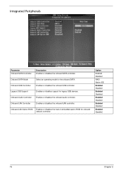
Onboard SATA Mode Select an operating mode for legacy USB devices. Legacy USB Support Enables or disables support for the onboard SATA. Option Enabled Disabled RAID Native IDE Enabled Disabled Enabled Disabled Enabled Disabled Enabled Disabled Enabled Disabled 19 Chapter 2 Onboard LAN Option ROM Enables or disables the load of embedded option ROM for onboard network controller. Onboard USB Controller Enables or disables the onboard USB controller. Onboard LAN Controller Enables or disables the onboard LAN controller. Onboard Audio Controller Enables or disables the ...
Onboard SATA Mode Select an operating mode for legacy USB devices. Legacy USB Support Enables or disables support for the onboard SATA. Option Enabled Disabled RAID Native IDE Enabled Disabled Enabled Disabled Enabled Disabled Enabled Disabled Enabled Disabled 19 Chapter 2 Onboard LAN Option ROM Enables or disables the load of embedded option ROM for onboard network controller. Onboard USB Controller Enables or disables the onboard USB controller. Onboard LAN Controller Enables or disables the onboard LAN controller. Onboard Audio Controller Enables or disables the ...
Service Guide
Page 45
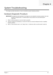
... 4 39 Verify the symptoms by attempting to perform. Non-Acer products, prototype cards, or modified options can give false errors and invalid system responses. 1. Obtain the failing symptoms in this chapter are only intended to test Acer products. Refer to "Power System check" and "Beep Codes" to determine which corrective action to recreate the failure by running the diagnostic tests or repeating thesame operation. 3.
... 4 39 Verify the symptoms by attempting to perform. Non-Acer products, prototype cards, or modified options can give false errors and invalid system responses. 1. Obtain the failing symptoms in this chapter are only intended to test Acer products. Refer to "Power System check" and "Beep Codes" to determine which corrective action to recreate the failure by running the diagnostic tests or repeating thesame operation. 3.
Service Guide
Page 46
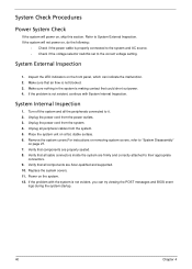
... if the power cable is properly connected to the system and AC source. • Check if the voltage selector switchis set to the correct voltage setting. Unplug the power cord from the system. 5. Remove the system covers.For instructions on removing system covers, refer to their appropriate connectors. 9. Verify that all components are Acer-qualified and supported. 10. System Internal Inspection 1. Verify that all cable connectors inside the...
... if the power cable is properly connected to the system and AC source. • Check if the voltage selector switchis set to the correct voltage setting. Unplug the power cord from the system. 5. Remove the system covers.For instructions on removing system covers, refer to their appropriate connectors. 9. Verify that all components are Acer-qualified and supported. 10. System Internal Inspection 1. Verify that all cable connectors inside the...
Service Guide
Page 47
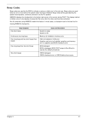
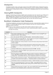
... screen during POST. CMOS checksum error or CMOS battery loss occurs. Beep Codes Beep codes are used by the system board speaker, commonly referred to as the PC speaker. Beep codes will be generated by the BIOS to indicate a serious or fatal error to execute the default procedures. This display method is OK. System is limited, since it only displays checkpoints that occur after the video card has been activated. Memory not installed or memory error. Graphics card error...
... screen during POST. CMOS checksum error or CMOS battery loss occurs. Beep Codes Beep codes are used by the system board speaker, commonly referred to as the PC speaker. Beep codes will be generated by the BIOS to indicate a serious or fatal error to execute the default procedures. This display method is OK. System is limited, since it only displays checkpoints that occur after the video card has been activated. Memory not installed or memory error. Graphics card error...
Service Guide
Page 48
... diagnostic card. Early super I /O port 80h.The BIOS outputs checkpoints throughout bootblock and Power-On Self Test (POST) to lower system memory and control is enabled. Verifythat flat mode is done. See Bootblock Recovery Code Checkpoints sectionfor more information. 42 Chapter 4 Store the Uncompressed pointer for more information. Copying Main BIOS into register. Checkpoint sare very useful in aiding software developers or technicians in PCI devices. This display...
... diagnostic card. Early super I /O port 80h.The BIOS outputs checkpoints throughout bootblock and Power-On Self Test (POST) to lower system memory and control is enabled. Verifythat flat mode is done. See Bootblock Recovery Code Checkpoints sectionfor more information. 42 Chapter 4 Store the Uncompressed pointer for more information. Copying Main BIOS into register. Checkpoint sare very useful in aiding software developers or technicians in PCI devices. This display...
Service Guide
Page 49
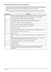
... back to read from add-in PCI devices. Start reading the recovery file cluster by the recovery file. Make flash write enabled through chipset and OEM specific method. Erase the flash part Program the flash part. Restore CPUID value back into register. Enable ATAPI hardware. Disable ATAPI hardware. Jump back to F000 ROM at F000:FFF0h. Search for pre-defined recovery file name in the super I/O. Give control to checkpoint E9. L1...
... back to read from add-in PCI devices. Start reading the recovery file cluster by the recovery file. Make flash write enabled through chipset and OEM specific method. Erase the flash part Program the flash part. Restore CPUID value back into register. Enable ATAPI hardware. Disable ATAPI hardware. Jump back to F000 ROM at F000:FFF0h. Search for pre-defined recovery file name in the super I/O. Give control to checkpoint E9. L1...
Service Guide
Page 52
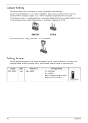
The illustrations show a 2-pin jumper.When the jumper cap is placed on the correct pins. This illustration shows a 3-pin jumper.Pins 1 and 2 are placed on just one pin are numbered. Jumper CLR_CMOS1 Type Description 3-pin Clear CMOS Setting (default) 1-2: NORMAL 2-3: CLEAR Before clearing theCMOS, make sure toturn off the system. CLR_CMOS1 46 Chapter 5 Use the motherboard jumpers to set system configuration options. When setting the jumpers, ensure that the jumper caps are numbered. Setting Jumper Use the motherboard jumpers to set jumper for correct configuration of the ...
The illustrations show a 2-pin jumper.When the jumper cap is placed on the correct pins. This illustration shows a 3-pin jumper.Pins 1 and 2 are placed on just one pin are numbered. Jumper CLR_CMOS1 Type Description 3-pin Clear CMOS Setting (default) 1-2: NORMAL 2-3: CLEAR Before clearing theCMOS, make sure toturn off the system. CLR_CMOS1 46 Chapter 5 Use the motherboard jumpers to set system configuration options. When setting the jumpers, ensure that the jumper caps are numbered. Setting Jumper Use the motherboard jumpers to set jumper for correct configuration of the ...
Service Guide
Page 59
... (Field Replaceable Unit) list in the FRU list of the Aspire R3700 desktop computer. For whatever reasons a part number is changed, it will be noted on your regional Acer office on how to -date information available on the printed Service Guide. NOTES: • When ordering FRU parts, check the most up-to return it properly, or follow the rules set by your Acer office may...
... (Field Replaceable Unit) list in the FRU list of the Aspire R3700 desktop computer. For whatever reasons a part number is changed, it will be noted on your regional Acer office on how to -date information available on the printed Service Guide. NOTES: • When ordering FRU parts, check the most up-to return it properly, or follow the rules set by your Acer office may...


