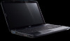
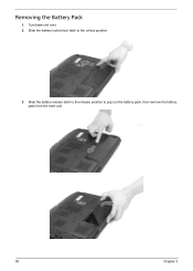
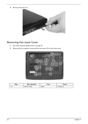
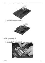
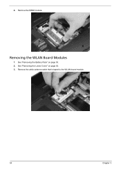
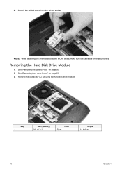
Aspire 5235 / 5535 Series User's Guide EN
Page 9
9 Base view English # Icon Item 1 Battery bay Description Houses the computer's battery pack. 2 Battery release latch Releases the battery for removal. 3 Battery lock Locks the battery in position. 4 Memory compartment Houses the computer's main memory. 5 Hard disk bay Houses the computer's hard disk (secured with screws). 6 Ventilation slots and Enable the computer to stay cool, even cooling fan after prolonged use. Note: Do not cover or obstruct the opening of the fan.
Aspire 5235 / 5535 Service Guide
Page 7
... certain models 14 Acer Empowering Technology 15 Launching Acer Empowering Technology 15 Empowering Technology password 16 Acer eAudio Management (only for certain models 17 Acer ePower Management 18 Acer eDataSecurity Management (only for certain models 19 Acer eRecovery Management 20 Acer eSettings Management 22 ...Pre-disassembly Instructions 48 Disassembly Process 48 External Module Disassembly Process 49 External Modules Disassembly Flowchart 49 Removing the Battery Pack 50 Removing the SD dummy card 51 Removing the ExpressCard dummy card 51 Removing the Lower Cover 52...
Aspire 5235 / 5535 Service Guide
Page 18
Note: Do not cover or obstruct the opening of the fan. 8 Chapter 1 Bottom View Icon Item Description 1 Battery bay Houses the computer's battery pack. 2 Battery release Releases the battery for removal. latch 3 Battery lock Locks the battery in position. 4 Memory Houses the computer's main memory. compartment 5 Hard disk bay Houses the computer's hard disk (secured with screws). 6 Ventilation slots Enable the computer to stay cool, even after and cooling fan prolonged use.
Aspire 5235 / 5535 Service Guide
Page 19
...+ VOL- Indicates the status of Bluetooth communication. Lights up when Num Lock is closed. Charging: The light shows amber when the battery is active. Easy-Launch Buttons Located beside the keyboard are visible even when the computer cover is activated. They are called easy-launch...can be reset by clicking on Start, All Programs, and then Launch Manager to -read status indicators. Increases the sound volume. Launch Acer Empowering Technology (userprogrammable) Chapter 1 9 Indicates the status of wireless LAN communication. Fully charged: The light shows green when in AC...
Aspire 5235 / 5535 Service Guide
Page 25
...: The following content is for you to access frequently used functions and manage your system (only for certain models). • Acer ePower Management optimizes battery usage via customizable power plans. • Acer eDataSecurity Management protects data with a particular utility, launch the utility and click the icon at the bottom of Dolby Home Theater...
Aspire 5235 / 5535 Service Guide
Page 28
...name for your mouse over the Acer ePower Management Technology toolbar. You may...select Acer ePower Management from the Empowering Technology toolbar, run the program from the Acer ... tray and select Acer ePower Management. Select...For more power options, click in the Acer ePower Management utility, or right-click the ...Acer ePower Management application. You can revert to another one first. 1. Using power plans Acer... 5. Acer ePower Management Acer ePower Management features a straightforward user interface for configuring your customized plan on the Acer Empowering ...
Aspire 5235 / 5535 Service Guide
Page 29
...Windows Explorer as a shell extension for Lotus Notes and Microsoft Outlook. Battery status 1. It is an encryption utility that protects your files from being accessed by default. On first use, the Acer eDataSecurity Management setup wizard will use this password to access the Personal...quick data encryption/decryption and also supports on current usage. 2. You can also launch the Acer ePower Management application and refer to view remaining battery life, battery status, and remaining battery life in standby and hibernate modes. The Master Password may also be used to create the...
Aspire 5235 / 5535 Service Guide
Page 42
.../AUO/LG 15.4 inches 1280 x 800 WXGA 0.204 x 0.204 R.G.B. OS initiated shutdown. All devices in the system are turned off completely. Battery Item Vendor Battery Type Pack capacity Number of battery cell Package configuration LCD 15.4" inch Item Vendor & model name Screen Diagonal (mm) Display resolution (pixels) Pixel Pitch Pixel Arrangement Display Mode...
Aspire 5235 / 5535 Service Guide
Page 56
... or options • Restore a BIOS when it becomes corrupted. Prepare a bootable diskette. 2. Copy the flash utilities to update the system BIOS flash ROM. If the battery pack does not contain enough power to run the Flash utility. Then boot the system from the bootable diskette. Fellow the steps below to finish...
Aspire 5235 / 5535 Service Guide
Page 60
..., then disassemble the inside assembly frame in the succeeding disassembly sections illustrate the entire disassembly sequence. Unplug the AC adapter and all peripherals. 2. Remove the battery pack. For example, if you want to any of the hardware components. Turn off the power to the system and all power and signal cables...
Aspire 5235 / 5535 Service Guide
Page 61
... on the entire disassembly sequence and instructs you on the components that order. EXTERNAL MODULE DISASSEMBLY TURN OFF POWER AND PERIPHERALS UNPLUG POWER CABLES REMOVE BATTERY PACK SD DUMMY CARD ExpressCard DUMMY CARD Captive Screwx4 Ax6 LOWER COVER Hx1 WLAN BOARD DIMM MODULES ODD MODULE Cx1 HDD MODULE OPTICAL DISK DRIVE...
Aspire 5235 / 5535 Service Guide
Page 62
Slide the battery release latch to the release position to the unlock position. 3. Turn base unit over. 2. Slide the battery lock/unlock latch to pop out the battery pack, then remove the battery pack from the main unit. 50 Chapter 3 Removing the Battery Pack 1.
Aspire 5235 / 5535 Service Guide
Page 64
Removing the Lower Cover 1. Remove the four captive screws and the six screws (A) on page 50. 2. Step 1~6 Size (Quantity) M2.5 x L8 (6) Color Black Torque 3.0 kgf-cm 52 Chapter 3 Pull it out from the slot. 2. See "Removing the Battery Pack" on the lower cover.
Aspire 5235 / 5535 Service Guide
Page 65
Remove the lower cover from the lower case. Use a plastic screw driver to release the DIMM. See "Removing the Battery Pack" on both sides of the DIMM socket to carefully pry open the lower cover. 4. Push out the latches on page 50. 2. Chapter 3 53 See "Removing the Lower Cover" on page 52.. 3. Removing the DIMM 1. 3.
Aspire 5235 / 5535 Service Guide
Page 66
Remove the DIMM module. Remove the white antenna cable that is taped to the WLAN board module. 54 Chapter 3 See "Removing the Battery Pack" on page 52. 3. Removing the WLAN Board Modules 1. See "Removing the Lower Cover" on page 50. 2. 4.
Aspire 5235 / 5535 Service Guide
Page 68
Remove the one screw (C) securing the hard disk drive module. See "Removing the Battery Pack" on page 52. 3. Step 1 Size (Quantity) M2 x L3 (1) Color Silver Torque 1.6 kgf-cm 56 Chapter 3 See "Removing the Lower Cover" on page 50. 2. NOTE: When attaching the antenna back to the WLAN board, make sure the cable are arranged properly. Removing the Hard Disk Drive Module 1. Detach the WLAN board from the WLAN socket. 6.
Aspire 5235 / 5535 Service Guide
Page 70
See "Removing the Lower Cover" on page 50. 2. 7. Torque 3.0 kgf-cm 58 Chapter 3 Step 1~2 Size (Quantity) M3 x L4 (2) Color Silver Removing the Optical Drive Module 1. Remove the two screws (D) securing the hard disk to the bracket and remove the hard disk from the bracket. See "Removing the Battery Pack" on page 52.
Aspire 5235 / 5535 Service Guide
Page 74
Carefully pry loose the middle cover from the latches securing it and remove the middle cover. 62 Chapter 3 See "Removing the Battery Pack" on page 50. 2. Use a plastic screw driver to pry loose the side of the middle cover. 3. Removing the Middle Cover 1.
Aspire 5235 / 5535 Service Guide
Page 75
Push down on the touchpad area. Carefully pry loose the keyboard and turn it over on the lock and release the latches securing the keyboard to the upper case. 4. See "Removing the Middle Cover" on page 50. 2. Chapter 3 63 See "Removing the Battery Pack" on page 62. 3. Removing the Keyboard 1.
Aspire 5235 / 5535 Service Guide
Page 76
Removing the Heatsink Fan Module 1. Disconnect the heatsink fan connector from the main board to remove the keyboard. See "Removing the Battery Pack" on page 52. 3. See "Removing the Lower Cover" on page 50. 2. Disconnect the keyboard cable from the main board. 64 Chapter 3 5.