Quick Start Guide
Page 7
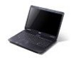
...up. The front panel indicators are visible even when the computer cover is charging. 2. 5 English # Icon 4 5 6 Item Keyboard Touchpad Power indicator1 Description For entering data into your hands when you use the computer. 9 Touchpad toggle Turns the internal touchpad on and off . Touch-...sensitive pointing device which functions like and right) the left and right buttons function like a computer mouse. Power button Turns the computer on and off . Indicates the computer's power status. Fully charged: The light shows blue when in AC mode. 7 Click buttons (left The left...
...up. The front panel indicators are visible even when the computer cover is charging. 2. 5 English # Icon 4 5 6 Item Keyboard Touchpad Power indicator1 Description For entering data into your hands when you use the computer. 9 Touchpad toggle Turns the internal touchpad on and off . Touch-...sensitive pointing device which functions like and right) the left and right buttons function like a computer mouse. Power button Turns the computer on and off . Indicates the computer's power status. Fully charged: The light shows blue when in AC mode. 7 Click buttons (left The left...

Quick Start Guide
Page 8
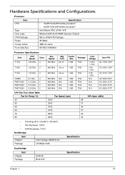
... and volume output. Volume down Volume up Decreases the screen brightness. Increases the sound volume. Speaker toggle Turns the speakers on and off to save power. English 6 Hotkeys The computer employs hotkeys or key combinations to the next media file.
... and volume output. Volume down Volume up Decreases the screen brightness. Increases the sound volume. Speaker toggle Turns the speakers on and off to save power. English 6 Hotkeys The computer employs hotkeys or key combinations to the next media file.
Service Guide
Page 7
Table of Contents System Specifications 1 Features 1 Optical Media Drive 2 System Block Diagram 5 Your Acer Notebook tour 6 Front View 6 Closed Front View 7 Left View 7 Right View 9 Bottom View 9 Indicators 10 TouchPad Basics 11 Using the Keyboard 12 Lock Keys and ... the Keyboard 58 Main Unit Disassembly Process 59 Main Unit Disassembly Flowchart 59 Removing the LCD Module 60 Removing the Upper Cover 65 Removing the Power Board 69 Removing the Left Speaker Module 70 Removing the TouchPad Bracket 72 VII
Table of Contents System Specifications 1 Features 1 Optical Media Drive 2 System Block Diagram 5 Your Acer Notebook tour 6 Front View 6 Closed Front View 7 Left View 7 Right View 9 Bottom View 9 Indicators 10 TouchPad Basics 11 Using the Keyboard 12 Lock Keys and ... the Keyboard 58 Main Unit Disassembly Process 59 Main Unit Disassembly Flowchart 59 Removing the LCD Module 60 Removing the Upper Cover 65 Removing the Power Board 69 Removing the Left Speaker Module 70 Removing the TouchPad Bracket 72 VII
Service Guide
Page 8
... 99 Replacing the Thermal Module 99 Replacing the Mainboard 100 Replacing the TouchPad Bracket 101 Replacing the Left Speaker Module 103 Replacing the Power Board 103 Replacing the Upper Cover 105 Replacing the LCD Module 109 Replacing the Keyboard 114 Replacing the Switch Cover 115 Replacing the... ODD Module 119 Replacing the Lower Covers 120 Replacing the SD Dummy Card 120 Replacing the Battery 121 Troubleshooting 123 Common Problems 123 Power On Issue 124 No Display Issue 125 Random Loss of BIOS Settings 126 LCD Failure 127 Built-In Keyboard Failure 127 TouchPad Failure...
... 99 Replacing the Thermal Module 99 Replacing the Mainboard 100 Replacing the TouchPad Bracket 101 Replacing the Left Speaker Module 103 Replacing the Power Board 103 Replacing the Upper Cover 105 Replacing the LCD Module 109 Replacing the Keyboard 114 Replacing the Switch Cover 115 Replacing the... ODD Module 119 Replacing the Lower Covers 120 Replacing the SD Dummy Card 120 Replacing the Battery 121 Troubleshooting 123 Common Problems 123 Power On Issue 124 No Display Issue 125 Random Loss of BIOS Settings 126 LCD Failure 127 Built-In Keyboard Failure 127 TouchPad Failure...
Service Guide
Page 9
Table of Contents Undetermined Problems 136 Post Codes 137 Jumper and Connector Locations 145 Top View 145 Bottom View 146 Power Board 147 Clearing Password Check and BIOS Recovery 148 Clearing Password Check 148 Clear CMOS Jumper 149 BIOS Recovery by Crisis Disk 150 FRU (Field ...
Table of Contents Undetermined Problems 136 Post Codes 137 Jumper and Connector Locations 145 Top View 145 Bottom View 146 Power Board 147 Clearing Password Check and BIOS Recovery 148 Clearing Password Check 148 Clear CMOS Jumper 149 BIOS Recovery by Crisis Disk 150 FRU (Field ...
Service Guide
Page 13
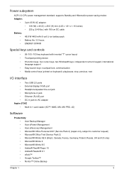
... standard: supports Standby and Hibernation power-saving modes Adapter: • 3-pin 65 W AC adapter: • 108 (W) x 46 (D) x 29.5 (H) mm (4.25 x 1.81 x 1.16 inches) • 225 g (0.49 lbs.) with 180 cm DC ...-in jack • Ethernet (RJ-45) port • DC-in jack for AC adapter Aspire 5734Z • Multi-in-1 card reader (SD™, MMC, MS, MS PRO, xD) Software Productivity • Acer Backup Manager • Acer ePower Management • Acer eRecovery Management • Microsoft® Office Personal 2007 (Service Pack 2) (Japan only, subject to...
... standard: supports Standby and Hibernation power-saving modes Adapter: • 3-pin 65 W AC adapter: • 108 (W) x 46 (D) x 29.5 (H) mm (4.25 x 1.81 x 1.16 inches) • 225 g (0.49 lbs.) with 180 cm DC ...-in jack • Ethernet (RJ-45) port • DC-in jack for AC adapter Aspire 5734Z • Multi-in-1 card reader (SD™, MMC, MS, MS PRO, xD) Software Productivity • Acer Backup Manager • Acer ePower Management • Acer eRecovery Management • Microsoft® Office Personal 2007 (Service Pack 2) (Japan only, subject to...
Service Guide
Page 16
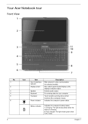
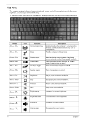
...: The light shows amber when the battery is charging. 2. Chapter 1 Delivers audio output. Indicates the computer's power status. Fully charged: The light shows green when in AC mode. Touch-sensitive pointing device which functions like ...), displays computer output. Battery indicator Indicates the computer's battery status. 1. For entering data into your computer. Your Acer Notebook tour Front View No. 1 2 3 4 5 6 6 Icon Item Acer Crystal Eye webcam Display screen Speaker Keyboard Touchpad Power indicator Description Web camera for video communication (for selected models).
...: The light shows amber when the battery is charging. 2. Chapter 1 Delivers audio output. Indicates the computer's power status. Fully charged: The light shows green when in AC mode. Touch-sensitive pointing device which functions like ...), displays computer output. Battery indicator Indicates the computer's battery status. 1. For entering data into your computer. Your Acer Notebook tour Front View No. 1 2 3 4 5 6 6 Icon Item Acer Crystal Eye webcam Display screen Speaker Keyboard Touchpad Power indicator Description Web camera for video communication (for selected models).
Service Guide
Page 17
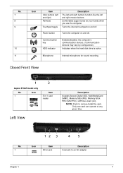
... PRO), xDPicture Card (xD). Turns the internal touchpad on and off . Only one card can operate at any given time. Power button Turns the computer on and off . Closed Front View Aspire 5734Z model only No. 1 Icon Item 5-in jack Description Connects to remove/install the card. No. 7 8 9 10 11 Icon Item...
... PRO), xDPicture Card (xD). Turns the internal touchpad on and off . Only one card can operate at any given time. Power button Turns the computer on and off . Closed Front View Aspire 5734Z model only No. 1 Icon Item 5-in jack Description Connects to remove/install the card. No. 7 8 9 10 11 Icon Item...
Service Guide
Page 20
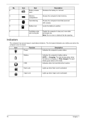
... computer to -read status indicators. Caps Lock Lights up when Num Lock is activated. 10 Chapter 1 Houses the computer's main memory. Icon Function Power Description Indicates the computer's power status. No. 2 3 4 5 Icon Item Battery release latch Memory compartment Hard disk bay Battery lock Description Releases the battery for removal. Note: Do not...
... computer to -read status indicators. Caps Lock Lights up when Num Lock is activated. 10 Chapter 1 Houses the computer's main memory. Icon Function Power Description Indicates the computer's power status. No. 2 3 4 5 Icon Item Battery release latch Memory compartment Hard disk bay Battery lock Description Releases the battery for removal. Note: Do not...
Service Guide
Page 24
... computer's communication devices. (Communication devices may vary by configuration.) Puts the computer in the hotkey combination. Turns the internal touchpad on and off to save power.
... computer's communication devices. (Communication devices may vary by configuration.) Puts the computer in the hotkey combination. Turns the internal touchpad on and off to save power.
Service Guide
Page 25
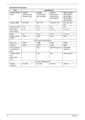
Hardware Specifications and Configurations Processor Item CPU Type Core Logic CPU Package Power On-die Cache Front Side Bus Specification • Intel® Pentium® mobile processor* • Intel® Celeron® mobile processor* Intel Mobile PDC uPGA -... N/A Cache Size 1 MB 1 MB 1 MB 1 MB 1 MB 1 MB 1 MB Package PGA PGA PGA PGA PGA PGA PGA Core Voltage 1.075V1.175V 0.951.30V 0.951.30V N/A N/A N/A N/A Acer P/N KC.17001.CMT KC.30001.CMT KC.31001.CMT KC.N0001.900 KC.34001.DTP KC.42001.DTP KC.45001.DTP CPU Fan True Value...
Hardware Specifications and Configurations Processor Item CPU Type Core Logic CPU Package Power On-die Cache Front Side Bus Specification • Intel® Pentium® mobile processor* • Intel® Celeron® mobile processor* Intel Mobile PDC uPGA -... N/A Cache Size 1 MB 1 MB 1 MB 1 MB 1 MB 1 MB 1 MB Package PGA PGA PGA PGA PGA PGA PGA Core Voltage 1.075V1.175V 0.951.30V 0.951.30V N/A N/A N/A N/A Acer P/N KC.17001.CMT KC.30001.CMT KC.31001.CMT KC.N0001.900 KC.34001.DTP KC.42001.DTP KC.45001.DTP CPU Fan True Value...
Service Guide
Page 28
... max) 8 MB SATA Voltage tolerance 5V ±5% 512 512 4, 2 4, 2, 2 2 or 1, 1 5400 2, 1, 1 5400 Performance Specifications 8 MB 8 MB SATA SATA 352 395~952 (typical) 150 300 DC Power Requirements 5V ±5% 5V ±5% Western Digital WD5000BEVT WD3200BEVT WD2500BEVT WD1600BEVT 500, 320, 250, 160 512 4, 4, 3, 2 2, 2, 2, 1 5400 8 MB SATA 850 Mbits/s maximum 300 maximum 5V...
... max) 8 MB SATA Voltage tolerance 5V ±5% 512 512 4, 2 4, 2, 2 2 or 1, 1 5400 2, 1, 1 5400 Performance Specifications 8 MB 8 MB SATA SATA 352 395~952 (typical) 150 300 DC Power Requirements 5V ±5% 5V ±5% Western Digital WD5000BEVT WD3200BEVT WD2500BEVT WD1600BEVT 500, 320, 250, 160 512 4, 4, 3, 2 2, 2, 2, 1 5400 8 MB SATA 850 Mbits/s maximum 300 maximum 5V...
Service Guide
Page 29
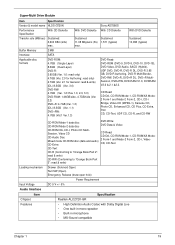
.... 1.0: read only) 4.7GB (Ver. 2.0 for Authoring: read only) 4.7GB (Ver. 2.1 for General: read & write) Drawer (Solenoid Open) Tact SW (Open) Emergency Release (draw open hole) Power Requirement DC 5 V +/- 5% Specification Realtek ALC272X-GR • High Definition Audio Codec with Dolby Digital Live • One built-in mono speaker • Built-in microphone...
.... 1.0: read only) 4.7GB (Ver. 2.0 for Authoring: read only) 4.7GB (Ver. 2.1 for General: read & write) Drawer (Solenoid Open) Tact SW (Open) Emergency Release (draw open hole) Power Requirement DC 5 V +/- 5% Specification Realtek ALC272X-GR • High Definition Audio Codec with Dolby Digital Live • One built-in mono speaker • Built-in microphone...
Service Guide
Page 30
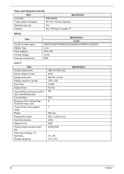
...Pixel Pitch Display Mode Typical White Luminance (cd/m2) (also called Brightness) Contrast Ratio Response Time (Optical Rise Time/Fall Time) msec Typical Power Consumption (watt) Weight Physical Size (mm) Electrical Interface Support Color Viewing Angle (up/down/right/ left) Temperature Range (°C) Operating Storage ...:1 8 7 580 max. 398.1 x 232.8 x 5.5 LVDS 262K 20/45/45/45 0 to +50 -20 to +60 Specification 20 Chapter 1 Power and Keyboard Controller Item Controller Total number of keypads Specification ENE KB926 99-/100-/103-key keyboard Windows logo key Hotkeys Yes See "Hot Keys...
...Pixel Pitch Display Mode Typical White Luminance (cd/m2) (also called Brightness) Contrast Ratio Response Time (Optical Rise Time/Fall Time) msec Typical Power Consumption (watt) Weight Physical Size (mm) Electrical Interface Support Color Viewing Angle (up/down/right/ left) Temperature Range (°C) Operating Storage ...:1 8 7 580 max. 398.1 x 232.8 x 5.5 LVDS 262K 20/45/45/45 0 to +50 -20 to +60 Specification 20 Chapter 1 Power and Keyboard Controller Item Controller Total number of keypads Specification ENE KB926 99-/100-/103-key keyboard Windows logo key Hotkeys Yes See "Hot Keys...
Service Guide
Page 32
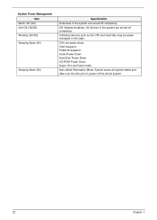
... completely. OS initiated shutdown. System saves all system states and data onto the disc prior to power off completely. CPU set power down VGA Suspend PCMCIA Suspend Audio Power Down Hard Disk Power Down CD-ROM Power Down Super I/O Low Power mode Also called Hibernation Mode. Off (G3) Soft Off (G2/S5) Working (G0/S0) Sleeping...
... completely. OS initiated shutdown. System saves all system states and data onto the disc prior to power off completely. CPU set power down VGA Suspend PCMCIA Suspend Audio Power Down Hard Disk Power Down CD-ROM Power Down Super I/O Low Power mode Also called Hibernation Mode. Off (G3) Soft Off (G2/S5) Working (G0/S0) Sleeping...
Service Guide
Page 41
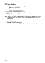
... loaded. Follow the steps below to the bootable diskette. 3. NOTE: Do not install memory-related drivers (XMS, EMS, DPMI) when you use the AC adaptor power supply when you run the Flash. 1. Prepare a bootable diskette. 2. Chapter 2 31 NOTE: If you do not have a crisis recovery diskette at hand, then you should... when it becomes corrupted. Use the Flash utility to finish BIOS flash, you use the Flash utility. If the battery pack does not contain enough power to update the system BIOS flash ROM.
... loaded. Follow the steps below to the bootable diskette. 3. NOTE: Do not install memory-related drivers (XMS, EMS, DPMI) when you use the AC adaptor power supply when you run the Flash. 1. Prepare a bootable diskette. 2. Chapter 2 31 NOTE: If you do not have a crisis recovery diskette at hand, then you should... when it becomes corrupted. Use the Flash utility to finish BIOS flash, you use the Flash utility. If the battery pack does not contain enough power to update the system BIOS flash ROM.

Service Guide
Page 43
Flash is not connected, the following message displays. 4. Plug in the AC power to continue. 5. NOTE: If the AC power is complete when the message Flash programming complete displays. Chapter 2 33 In flash BIOS, the message Please do not remove AC Power Source displays.
Flash is not connected, the following message displays. 4. Plug in the AC power to continue. 5. NOTE: If the AC power is complete when the message Flash programming complete displays. Chapter 2 33 In flash BIOS, the message Please do not remove AC Power Source displays.

Service Guide
Page 51
Plug in AC power. Press Fn +esc keys and hold them down, then plug in the USB Flash Disk without AC plug. 2. Press power button and the system will enter crisis mode to the USB flash disk root directory. Chapter 2 41 Using the crisis disk 1. NOTE: Do not place any other *.fd files to flash the BIOS. Copy the PAWF5x64.fd file to the USB flash disk root directory. The power button flashes orange. 3. 4.
Plug in AC power. Press Fn +esc keys and hold them down, then plug in the USB Flash Disk without AC plug. 2. Press power button and the system will enter crisis mode to the USB flash disk root directory. Chapter 2 41 Using the crisis disk 1. NOTE: Do not place any other *.fd files to flash the BIOS. Copy the PAWF5x64.fd file to the USB flash disk root directory. The power button flashes orange. 3. 4.
Service Guide
Page 54
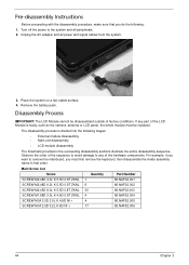
... the following : 1. Disassembly Process IMPORTANT: The LCD Module cannot be replaced. For example, if you want to the system and all power and signal cables from the system. 3. Turn off the power to remove the mainboard, you do the following stages: • External module disassembly • Main unit disassembly • LCD module...
... the following : 1. Disassembly Process IMPORTANT: The LCD Module cannot be replaced. For example, if you want to the system and all power and signal cables from the system. 3. Turn off the power to remove the mainboard, you do the following stages: • External module disassembly • Main unit disassembly • LCD module...
Service Guide
Page 55
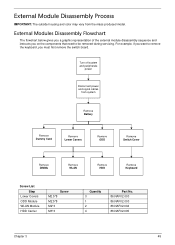
... the keyboard, you want to be removed during servicing. For example, if you must first remove the switch board. Turn off system and peripherals power Disconnect power and signal cables from the mass produced model. External Module Disassembly Process IMPORTANT: The outside housing and color may vary from system Remove Battery Remove...
... the keyboard, you want to be removed during servicing. For example, if you must first remove the switch board. Turn off system and peripherals power Disconnect power and signal cables from the mass produced model. External Module Disassembly Process IMPORTANT: The outside housing and color may vary from system Remove Battery Remove...


