Aspire 3630 / TravelMate 2430 Service Guide
Page 8
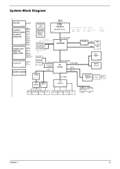
... 3VSUS/5VSUS 3V_S5 5V_S5 Page:24 3VSUS 5VSUS 2.5VSUS/+2.5/VTT MVREF_DM SMDDR_VTERM 2.5VSUS +2.5V VTT MVREF_DM SMDDR_VTERM Page:25 +1.8V/1.8V_S5 1.8V_S5 +1.8V Page:25 BATTERY CHARGER ZL6 CLOCK GEN ICS 952023CG +3.3V Page:13 CPU CELERON-M INTEL Mobile_479 CPU DDR CLOCK BUFFER ICS97322 +2.5V Page:13 VCC_CORE VTT CLK_SDRAM0~5, CLK_SDRAM0...
... 3VSUS/5VSUS 3V_S5 5V_S5 Page:24 3VSUS 5VSUS 2.5VSUS/+2.5/VTT MVREF_DM SMDDR_VTERM 2.5VSUS +2.5V VTT MVREF_DM SMDDR_VTERM Page:25 +1.8V/1.8V_S5 1.8V_S5 +1.8V Page:25 BATTERY CHARGER ZL6 CLOCK GEN ICS 952023CG +3.3V Page:13 CPU CELERON-M INTEL Mobile_479 CPU DDR CLOCK BUFFER ICS97322 +2.5V Page:13 VCC_CORE VTT CLK_SDRAM0~5, CLK_SDRAM0...
Aspire 3630 / TravelMate 2430 Service Guide
Page 10
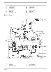
31 PCMCIA Connector 33 USB Connector 35 Microphone Jack 37 WLAN Button 39 Battery LED 41 Audio Codec ALC203 Bottom View 32 HDD Connector 34 LineOut Jack 36 LineIn Jack 38 Bluetooth button 40 Power LED 42 FAN Connector [02] [03] [01] [05] [06] [07] [08] 1 Lid Switch 3 LED Board Connector Chapter 1 [04] 2 Panel Connector 4 Modem Connector [09] [10] [11] [12] 5
31 PCMCIA Connector 33 USB Connector 35 Microphone Jack 37 WLAN Button 39 Battery LED 41 Audio Codec ALC203 Bottom View 32 HDD Connector 34 LineOut Jack 36 LineIn Jack 38 Bluetooth button 40 Power LED 42 FAN Connector [02] [03] [01] [05] [06] [07] [08] 1 Lid Switch 3 LED Board Connector Chapter 1 [04] 2 Panel Connector 4 Modem Connector [09] [10] [11] [12] 5
Aspire 3630 / TravelMate 2430 Service Guide
Page 13
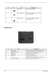
... wireless function. Press to audio line-out devices (e.g., speakers, headphones). Lights up when the battery is on page 10 # 1 2 Icon Speakers Item/ Port Power indicator # Icon Item Description 3 Battery indicator Description Left and right speakers deliver stereo audio output. Indicates the status of Bluetooth communication ...) Wireless communication button/ Desincdriipctaitoonr Line-in jack Press to Universal Serial Bus (USB) 2.0 devices (e.g., USB mouse, UsB camera). 8 Aspire 3630 Accepts audio line-in jack Description Accepts inputs from external microphones.
... wireless function. Press to audio line-out devices (e.g., speakers, headphones). Lights up when the battery is on page 10 # 1 2 Icon Speakers Item/ Port Power indicator # Icon Item Description 3 Battery indicator Description Left and right speakers deliver stereo audio output. Indicates the status of Bluetooth communication ...) Wireless communication button/ Desincdriipctaitoonr Line-in jack Press to Universal Serial Bus (USB) 2.0 devices (e.g., USB mouse, UsB camera). 8 Aspire 3630 Accepts audio line-in jack Description Accepts inputs from external microphones.
Aspire 3630 / TravelMate 2430 Service Guide
Page 15
... to a display device (e.g., external monitor, LCD projector). House the computer's main memory. 10 Aspire 3630 Locks the battery in place. # 1 2 3 Icon Port Power jack Description Connects to remove the battery pack. Unlatches the battery to an AC adaptor. Houses the computer's battery pack. Note: Do not cover or obstruct the opening of the fan. Bottom view...
... to a display device (e.g., external monitor, LCD projector). House the computer's main memory. 10 Aspire 3630 Locks the battery in place. # 1 2 3 Icon Port Power jack Description Connects to remove the battery pack. Unlatches the battery to an AC adaptor. Houses the computer's battery pack. Note: Do not cover or obstruct the opening of the fan. Bottom view...
Aspire 3630 / TravelMate 2430 Service Guide
Page 16
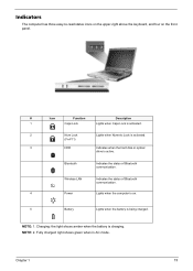
...the front panel. NOTE: 2. NOTE: 1. Wireless LAN Indicates the status of Bluetooth communication. Charging: the light shows amber when the battery is active. Fully charged: light shows green when in AC mode. Chapter 1 11 Indicators The computer has three easy-to-read status... icons on the upper-right above the keyboard, and four on . 5 Battery Lights when the battery is being charged. Icon Function Description # Icon Function Description 1 Caps Lock Lights when Caps Lock is activated. 2 Num Lock Lights...
...the front panel. NOTE: 2. NOTE: 1. Wireless LAN Indicates the status of Bluetooth communication. Charging: the light shows amber when the battery is active. Fully charged: light shows green when in AC mode. Chapter 1 11 Indicators The computer has three easy-to-read status... icons on the upper-right above the keyboard, and four on . 5 Battery Lights when the battery is being charged. Icon Function Description # Icon Function Description 1 Caps Lock Lights when Caps Lock is activated. 2 Num Lock Lights...
Aspire 3630 / TravelMate 2430 Service Guide
Page 31
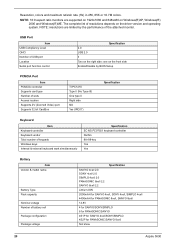
...complete list of USB port Location Serial port function control Specification 2.0 USB 2.0 3 Two on the front side Enable/Disable by the performance of battery cell Package configuration Package voltage Specification SANYO 4cell 2.0 SONY 4cell 2.0 SIMPLO 4cell 2.0 PANASONIC 8cell 2.2 SANYO 8cell 2.2 Lithium-ION 2000mAH for SANYO ...8V 4 for SANYO/SONY/SIMPLO 8 for PANASONIC/SANYO 4S1P for SANYO 4cell/SONY/SIMPLO 4S2P for PANASONIC/SANYO 8cell Not show 26 Aspire 3630 Resolution, colors and maximum refersh rate (Hz) in 256, 65K or 16.7M colors. USB Port Item USB Compliancy Level OHCI ...
...complete list of USB port Location Serial port function control Specification 2.0 USB 2.0 3 Two on the front side Enable/Disable by the performance of battery cell Package configuration Package voltage Specification SANYO 4cell 2.0 SONY 4cell 2.0 SIMPLO 4cell 2.0 PANASONIC 8cell 2.2 SANYO 8cell 2.2 Lithium-ION 2000mAH for SANYO ...8V 4 for SANYO/SONY/SIMPLO 8 for PANASONIC/SANYO 4S1P for SANYO 4cell/SONY/SIMPLO 4S2P for PANASONIC/SANYO 8cell Not show 26 Aspire 3630 Resolution, colors and maximum refersh rate (Hz) in 256, 65K or 16.7M colors. USB Port Item USB Compliancy Level OHCI ...
Aspire 3630 / TravelMate 2430 Service Guide
Page 36
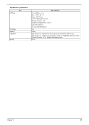
Mechanical Specification I/O Ports Item Drive Bays Material Indicators Switch Specification Three USB 2.0 ports Ethernet (RJ-45) port Modem (RJ-11) port External display (VGA) port Microphone/line-in jack Headphones/speaker/line-out jack Type II PC Card slot DC-in jack for AC adaptor One Plastic LED indicator for keyboard hot key: Caps Lock, Scroll Lock, NUmber lock LED indicator for function indicator: System power-on, HDD/ODD, Wireless on/off, Arcade LED mode, DC-in, Battery/Charging indicator Power Chapter 1 31
Mechanical Specification I/O Ports Item Drive Bays Material Indicators Switch Specification Three USB 2.0 ports Ethernet (RJ-45) port Modem (RJ-11) port External display (VGA) port Microphone/line-in jack Headphones/speaker/line-out jack Type II PC Card slot DC-in jack for AC adaptor One Plastic LED indicator for keyboard hot key: Caps Lock, Scroll Lock, NUmber lock LED indicator for function indicator: System power-on, HDD/ODD, Wireless on/off, Arcade LED mode, DC-in, Battery/Charging indicator Power Chapter 1 31
Aspire 3630 / TravelMate 2430 Service Guide
Page 48
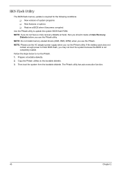
BIOS Flash Utility The BIOS flash memory update is not completely loaded. Then boot the system from the bootable diskette. If the battery pack does not contain enough power to the bootable diskette. 3. Fellow the steps below to update the system BIOS flash ROM. Use the Phlash utility ...
BIOS Flash Utility The BIOS flash memory update is not completely loaded. Then boot the system from the bootable diskette. If the battery pack does not contain enough power to the bootable diskette. 3. Fellow the steps below to update the system BIOS flash ROM. Use the Phlash utility ...
Aspire 3630 / TravelMate 2430 Service Guide
Page 53
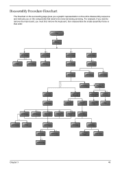
... HDD Holder *2 Dimm Cover Memory *1 Modem Cover *2 Modem Board Hinge Caps *2 Middle Cover Keyboard *6 LCD Module *2 Launch Board Lower Case Assembly *2 FDD Module *3 *3 *11 *4 RTC Battery *3 Mini PCI Card Plate Upper Case Assembly Disconnect Wireless LAN Antenna *4 Thermal Module *4 Wireless LAN Antenna Touchpad Cover Wireless LAN Card CPU ODD Module *4 HDD...
... HDD Holder *2 Dimm Cover Memory *1 Modem Cover *2 Modem Board Hinge Caps *2 Middle Cover Keyboard *6 LCD Module *2 Launch Board Lower Case Assembly *2 FDD Module *3 *3 *11 *4 RTC Battery *3 Mini PCI Card Plate Upper Case Assembly Disconnect Wireless LAN Antenna *4 Thermal Module *4 Wireless LAN Antenna Touchpad Cover Wireless LAN Card CPU ODD Module *4 HDD...
Aspire 3630 / TravelMate 2430 Service Guide
Page 55
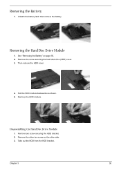
Remove the other two screw on page 50. 2. Remove the screw securing the hard disk drive (HDD) cover. 3. Disassembling the Hard Disc Drive Module 1. Removing the Hard Disc Drive Module 1. Pull the HDD module backwards as shown. 5. Remove the HDD module. Remove two screw securing the HDD bracket. 2. Chapter 3 50 Then remove the HDD cover. 4. See "Removing the Battery" on the other side. 3. Unlatch the battery latch then remove the battery. Removing the Battery 1. Take out the HDD from the HDD bracket.
Remove the other two screw on page 50. 2. Remove the screw securing the hard disk drive (HDD) cover. 3. Disassembling the Hard Disc Drive Module 1. Removing the Hard Disc Drive Module 1. Pull the HDD module backwards as shown. 5. Remove the HDD module. Remove two screw securing the HDD bracket. 2. Chapter 3 50 Then remove the HDD cover. 4. See "Removing the Battery" on the other side. 3. Unlatch the battery latch then remove the battery. Removing the Battery 1. Take out the HDD from the HDD bracket.
Aspire 3630 / TravelMate 2430 Service Guide
Page 56
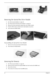
... Disc Drive Module" on page 50. 2. Remove the screw securing the optical disc drove (ODD) module. 4. Then remove the ODD module. See "Removing the Battery" on page 50. 3. Pop out the memory. 4. Disassembling the Optical Disc Drive Module 1. Removing the Memory 1. Push the ODD module outwards with a flat ... screw driver. 5. Remove the two screws securing the DIMM cover then remove the DIMM cover. 3. Then remove the ODD bracket. See "Removing the Battery" on page 50. 2. Remove two screws securing the ODD bracket. 2. Then remove the memory from the DIMM socket. 51 Chapter 3
... Disc Drive Module" on page 50. 2. Remove the screw securing the optical disc drove (ODD) module. 4. Then remove the ODD module. See "Removing the Battery" on page 50. 3. Pop out the memory. 4. Disassembling the Optical Disc Drive Module 1. Removing the Memory 1. Push the ODD module outwards with a flat ... screw driver. 5. Remove the two screws securing the DIMM cover then remove the DIMM cover. 3. Then remove the ODD bracket. See "Removing the Battery" on page 50. 2. Remove two screws securing the ODD bracket. 2. Then remove the memory from the DIMM socket. 51 Chapter 3
Aspire 3630 / TravelMate 2430 Service Guide
Page 58
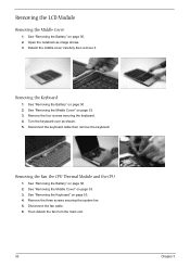
..., the CPU Thermal Module and the CPU 1. See "Removing the Keyboard" on page 50. 2. See "Removing the Battery" on page 53. 4. Open the notebook as shown. 5. See "Removing the Battery" on page 53. 3. Removing the LCD Module Removing the Middle Cover 1. See "Removing the Middle Cover" on page... 50. 2. Turn the keyboard over as image shows. 3. Then detach the fan from the main unit. 53 Chapter 3 See "Removing the Battery" on page 53. 3. Disconnect the fan cable. 6. See "Removing the Middle Cover" on page 50. 2. Detach the middle cover carefully then remove ...
..., the CPU Thermal Module and the CPU 1. See "Removing the Keyboard" on page 50. 2. See "Removing the Battery" on page 53. 4. Open the notebook as shown. 5. See "Removing the Battery" on page 53. 3. Removing the LCD Module Removing the Middle Cover 1. See "Removing the Middle Cover" on page... 50. 2. Turn the keyboard over as image shows. 3. Then detach the fan from the main unit. 53 Chapter 3 See "Removing the Battery" on page 53. 3. Disconnect the fan cable. 6. See "Removing the Middle Cover" on page 50. 2. Detach the middle cover carefully then remove ...
Aspire 3630 / TravelMate 2430 Service Guide
Page 59
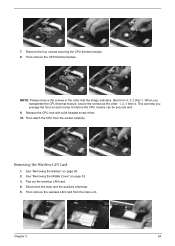
... LAN card. 4. Remove the four screws securing the CPU thermal module. 8. Then remove the CPU thermal module. This can be secured well. 9. See "Removing the Battery" on page 53. 3. Disconnect the main and the auxiliary antennae. 5. Chapter 3 54 Start from the main unit. Then remove the wireless LAN card from 4, 3, 2 then...
... LAN card. 4. Remove the four screws securing the CPU thermal module. 8. Then remove the CPU thermal module. This can be secured well. 9. See "Removing the Battery" on page 53. 3. Disconnect the main and the auxiliary antennae. 5. Chapter 3 54 Start from the main unit. Then remove the wireless LAN card from 4, 3, 2 then...
Aspire 3630 / TravelMate 2430 Service Guide
Page 60
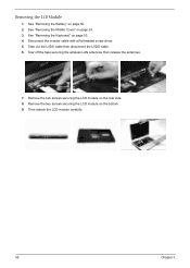
Take out the LVDS cable then disconnect the LVDS cable. 6. Remove the two screws securing the LCD module on the bottom. 9. Remove the two screws securing the LCD module on the rear side. 8. Disconnect the inverter cable with a flat headed screw driver. 5. See "Removing the Battery" on page 53. 4. See "Removing the Keyboard" on page 50. 2. Tear off the tape securing the wireless LAN antennae then release the antennae. 7. Then detach the LCD module carefully. 55 Chapter 3 See "Removing the Middle Cover" on page 53. 3. Removing the LCD Module 1.
Take out the LVDS cable then disconnect the LVDS cable. 6. Remove the two screws securing the LCD module on the bottom. 9. Remove the two screws securing the LCD module on the rear side. 8. Disconnect the inverter cable with a flat headed screw driver. 5. See "Removing the Battery" on page 53. 4. See "Removing the Keyboard" on page 50. 2. Tear off the tape securing the wireless LAN antennae then release the antennae. 7. Then detach the LCD module carefully. 55 Chapter 3 See "Removing the Middle Cover" on page 53. 3. Removing the LCD Module 1.
Aspire 3630 / TravelMate 2430 Service Guide
Page 61
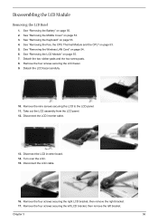
... page 54. 6. See "Removing the LCD Module" on page 50. 2. Disconnect the LCD inverter cable. 13. Detach the LCD bezel carefully. 10. See "Removing the Battery" on page 55. 7. See "Removing the Fan, the CPU Thermal Module and the CPU" on page 53. 4. Remove the nine screws securing the LCD to...
... page 54. 6. See "Removing the LCD Module" on page 50. 2. Disconnect the LCD inverter cable. 13. Detach the LCD bezel carefully. 10. See "Removing the Battery" on page 55. 7. See "Removing the Fan, the CPU Thermal Module and the CPU" on page 53. 4. Remove the nine screws securing the LCD to...
Aspire 3630 / TravelMate 2430 Service Guide
Page 63
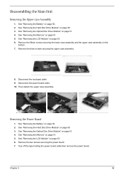
See "Removing the Battery" on page 51. 5. See "Removing the Memory" on page 50.. 2. Remove the fifteen screws securing the lower case assembly and the upper case assembly on ... securing the power board. 7. See "Removing the LCD Module" on page 50. 2. Disconnect the touchpad cable. 9. Then detach the upper case assembly. See "Removing the Battery" on page 53. 6. See "Removing the Hard Disc Drive Module" on page 53. 6. Tear off the tape holding the power board cable then remove the...
See "Removing the Battery" on page 51. 5. See "Removing the Memory" on page 50.. 2. Remove the fifteen screws securing the lower case assembly and the upper case assembly on ... securing the power board. 7. See "Removing the LCD Module" on page 50. 2. Disconnect the touchpad cable. 9. Then detach the upper case assembly. See "Removing the Battery" on page 53. 6. See "Removing the Hard Disc Drive Module" on page 53. 6. Tear off the tape holding the power board cable then remove the...
Aspire 3630 / TravelMate 2430 Service Guide
Page 64
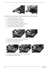
.... See "Removing the Upper Case Assembly" on page 50. 2. Then remove the touchpad bracket. 11. Then detach the touchpad carefully. 59 Chapter 3 See "Removing the Battery" on page 58. 6. See "Removing the Middle Cover" on page 53. 3. Remove the four screws securing the touchpad bracket. 9. Disconnect the touchpad FFC the remove...
.... See "Removing the Upper Case Assembly" on page 50. 2. Then remove the touchpad bracket. 11. Then detach the touchpad carefully. 59 Chapter 3 See "Removing the Battery" on page 58. 6. See "Removing the Middle Cover" on page 53. 3. Remove the four screws securing the touchpad bracket. 9. Disconnect the touchpad FFC the remove...
Aspire 3630 / TravelMate 2430 Service Guide
Page 65
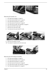
... the Keyboard" on page 60. See "Removing the Speaker Set" on page 53. 4. Disconnect the speaker set from the lower case. See "Removing the Battery" on page 58. 5. See "Removing the Power Board" on page 50. 2. See "Removing the Upper Case Assembly" on page 50. 2. See "Removing the... Battery" on page 58. 6. Disconnect the CIR receiver cable. 8. See "Removing the Middle Cover" on page 53. 3. Then disconnect the audio board FFC cable. 9. ...
... the Keyboard" on page 60. See "Removing the Speaker Set" on page 53. 4. Disconnect the speaker set from the lower case. See "Removing the Battery" on page 58. 5. See "Removing the Power Board" on page 50. 2. See "Removing the Upper Case Assembly" on page 50. 2. See "Removing the... Battery" on page 58. 6. Disconnect the CIR receiver cable. 8. See "Removing the Middle Cover" on page 53. 3. Then disconnect the audio board FFC cable. 9. ...
Aspire 3630 / TravelMate 2430 Service Guide
Page 66
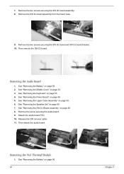
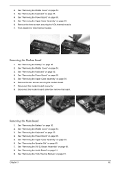
See "Removing the Middle Cover" on page 58. 5. See "Removing the Power Board" on page 53. 3. Removing the VGA Thermal Module 1. See "Removing the Battery" on page 53. 4. Removing the Audio Board 1. See "Removing the Keyboard" on page 50. 61 Chapter 3 Remove the two screws securing the SW DJ board .... Release the CIR receiver cable. 11. See "Removing the SW DJ Board Assembly" on page 50. 2. Then remove the SW DJ board. See "Removing the Battery" on page 60. 8.
See "Removing the Middle Cover" on page 58. 5. See "Removing the Power Board" on page 53. 3. Removing the VGA Thermal Module 1. See "Removing the Battery" on page 53. 4. Removing the Audio Board 1. See "Removing the Keyboard" on page 50. 61 Chapter 3 Remove the two screws securing the SW DJ board .... Release the CIR receiver cable. 11. See "Removing the SW DJ Board Assembly" on page 50. 2. Then remove the SW DJ board. See "Removing the Battery" on page 60. 8.
Aspire 3630 / TravelMate 2430 Service Guide
Page 67
...Disconnect the modem board connector. 8. See "Removing the Power Board" on page 58. 5. See "Removing the Keyboard" on page 50. 2. See "Removing the Battery" on page 53. 4. See "Removing the Upper Case Assembly" on page 53. 3. See "Removing the Middle Cover" on page 58. 6. See "Removing the...Module" on page 58. 5. See "Removing the Power Board" on page 61. Remove the two screws securing the modem board. 7. See "Removing the Battery" on page 58. 6. See "Removing the Upper Case Assembly" on page 50. 2. 2. Remove the three screws securing the VGA thermal module. 7. ...
...Disconnect the modem board connector. 8. See "Removing the Power Board" on page 58. 5. See "Removing the Keyboard" on page 50. 2. See "Removing the Battery" on page 53. 4. See "Removing the Upper Case Assembly" on page 53. 3. See "Removing the Middle Cover" on page 58. 6. See "Removing the...Module" on page 58. 5. See "Removing the Power Board" on page 61. Remove the two screws securing the modem board. 7. See "Removing the Battery" on page 58. 6. See "Removing the Upper Case Assembly" on page 50. 2. 2. Remove the three screws securing the VGA thermal module. 7. ...


