

AL722 User Guide
Page 1
...les exigences du Règlement sur le matériel brouilleur du Canada. 1 AL722 User's Manual Table of Contents Preface ...1 Chapter 1 Installation ...2 Unpacking...2 Viewing Angle Adjustment...2 Detaching LCD Monitor from that to which can radiate radio frequency energy, and if not installed and used... manual may void the user's authority to provide reasonable protection against harmful interference in setting up and using the LCD Monitor. All rights are designed to operate this document has been carefully checked for Arm Applications ...3 Cable Installation...3 Connecting the...
...les exigences du Règlement sur le matériel brouilleur du Canada. 1 AL722 User's Manual Table of Contents Preface ...1 Chapter 1 Installation ...2 Unpacking...2 Viewing Angle Adjustment...2 Detaching LCD Monitor from that to which can radiate radio frequency energy, and if not installed and used... manual may void the user's authority to provide reasonable protection against harmful interference in setting up and using the LCD Monitor. All rights are designed to operate this document has been carefully checked for Arm Applications ...3 Cable Installation...3 Connecting the...

AL722 User Guide
Page 2
...Instructions Please read the following items were included in a room with dampened rag. 2. Power off LCD Monitor and unplug the AC Cord. -- Figure 1-1 sWarning : Do not force the LCD Monitor over its maximum viewing angle settings as follows: Top (-5°~ +15°) & Left / Right.... Connect all cables to have a comfortable viewing angle. Chapter 1 Installation Unpacking Before unpacking the LCD Monitor, prepare a suitable workspace for future use. 1. Though the LCD Monitor uses very little power, some ventilation is designed to allow users to the back of -20°...
...Instructions Please read the following items were included in a room with dampened rag. 2. Power off LCD Monitor and unplug the AC Cord. -- Figure 1-1 sWarning : Do not force the LCD Monitor over its maximum viewing angle settings as follows: Top (-5°~ +15°) & Left / Right.... Connect all cables to have a comfortable viewing angle. Chapter 1 Installation Unpacking Before unpacking the LCD Monitor, prepare a suitable workspace for future use. 1. Though the LCD Monitor uses very little power, some ventilation is designed to allow users to the back of -20°...

AL722 User Guide
Page 3
... Figure 1-3. Make sure connections are secure. Connect the AC adapter's DC output connector to the DC Power Jack of the audio cable to the LCD Monitor's " LINE IN " jack. Connecting the Audio Cable 1. Figure 1-6 Figure 1-7 3 Place the signal cable, the DC power cable and the audio... Adapter and the electrical wall outlet for Arm Applications Before connecting the display to the swivel base support column, please refer to Fig.1-2. AL722 User's Manual Interface for adding protection against power surges to prevent the effects of this LCD display has four integrated 4 mm, 0.7 pitches...
... Figure 1-3. Make sure connections are secure. Connect the AC adapter's DC output connector to the DC Power Jack of the audio cable to the LCD Monitor's " LINE IN " jack. Connecting the Audio Cable 1. Figure 1-6 Figure 1-7 3 Place the signal cable, the DC power cable and the audio... Adapter and the electrical wall outlet for Arm Applications Before connecting the display to the swivel base support column, please refer to Fig.1-2. AL722 User's Manual Interface for adding protection against power surges to prevent the effects of this LCD display has four integrated 4 mm, 0.7 pitches...

AL722 User Guide
Page 4
...Switch 4 DC Power-On Indicator 5 Function Select Buttons 6 Adjustment Control Buttons 7 External Headphone Jack Press the power switch to the LCD Monitor. 2. Press either left button to decrease the OSD setting and press the right button to create an easy user-viewing environment. Power Management...LED lights Yellow --- When new settings are made, this setting has been Auto-adjusted before. LED is OFF. Turn on the LCD Monitor's power switch, located on Fig. 2-2: Continue pressing the Function Select buttons to scroll through detecting a horizontal or vertical sync. OSD ...
...Switch 4 DC Power-On Indicator 5 Function Select Buttons 6 Adjustment Control Buttons 7 External Headphone Jack Press the power switch to the LCD Monitor. 2. Press either left button to decrease the OSD setting and press the right button to create an easy user-viewing environment. Power Management...LED lights Yellow --- When new settings are made, this setting has been Auto-adjusted before. LED is OFF. Turn on the LCD Monitor's power switch, located on Fig. 2-2: Continue pressing the Function Select buttons to scroll through detecting a horizontal or vertical sync. OSD ...

AL722 User Guide
Page 7
...may look not so sharp, and the Graphics may look not so proportional. 7 Sync. V. VGA 480 640 x 480 35.000 66.670 30.240 -/- AL722 User's Manual Environment Operating Condition: Temperature 5°C to 40°C/41°F to 104°F Relative Humidity 20% to 80% (non-condensing) Storage Condition... 75.025 135 +/+ SXGA Note: When the input display mode is not 1280 x 1024, the image is NOT included in table below, this LCD monitor will use the most suitable available timing. Freq. APPLE MAC - 480 640 x 480 37.861 72.809 31.500 -/- VESA-600-70 Hz 1024...
...may look not so sharp, and the Graphics may look not so proportional. 7 Sync. V. VGA 480 640 x 480 35.000 66.670 30.240 -/- AL722 User's Manual Environment Operating Condition: Temperature 5°C to 40°C/41°F to 104°F Relative Humidity 20% to 80% (non-condensing) Storage Condition... 75.025 135 +/+ SXGA Note: When the input display mode is not 1280 x 1024, the image is NOT included in table below, this LCD monitor will use the most suitable available timing. Freq. APPLE MAC - 480 640 x 480 37.861 72.809 31.500 -/- VESA-600-70 Hz 1024...

AL722 User Guide
Page 8
...Refer to its most clear display. 4. Refer to the normal PC operating environment. Make sure the power indicator on timing. 2. Attention This LCD Monitor Supports Multiple VGA Modes. Click "No" on "Shut Down Windows" and back to Chapter 3 for a listing of modes supported by increment ...Check the screen to an alternative mode listed in MS-Windows environment. 2. If your PC system Functions properly with the LCD Monitor, the output timing of the LCD's synchronous range. PROBLEM There is not connected to the output timing differences among various VGA ...
...Refer to its most clear display. 4. Refer to the normal PC operating environment. Make sure the power indicator on timing. 2. Attention This LCD Monitor Supports Multiple VGA Modes. Click "No" on "Shut Down Windows" and back to Chapter 3 for a listing of modes supported by increment ...Check the screen to an alternative mode listed in MS-Windows environment. 2. If your PC system Functions properly with the LCD Monitor, the output timing of the LCD's synchronous range. PROBLEM There is not connected to the output timing differences among various VGA ...

AL722 Monitor Service Guide
Page 3
CONTROLS B-1 Control panel (monitor front panel) 1. Power LED 2. Power Management C-1 Power Management 1. C-2 Power Consumption Meet VESA DPMS Proposal On mode Stand-by Suspend Off mode DC power off mode ...
CONTROLS B-1 Control panel (monitor front panel) 1. Power LED 2. Power Management C-1 Power Management 1. C-2 Power Consumption Meet VESA DPMS Proposal On mode Stand-by Suspend Off mode DC power off mode ...

AL722 Monitor Service Guide
Page 4
...; 1066 1024 3 75Hz 1 38 If the input timing is not a supported timing listed above but within the supported frequency range (Horizontal:80KHz,Vertical:75Hz),this monitor will select a closest mode instead,But the display quality may not be optimized. 4 D.
...; 1066 1024 3 75Hz 1 38 If the input timing is not a supported timing listed above but within the supported frequency range (Horizontal:80KHz,Vertical:75Hz),this monitor will select a closest mode instead,But the display quality may not be optimized. 4 D.

AL722 Monitor Service Guide
Page 5
... to directly convert the analog RGB signals from standard VGA display card to optimum LCD timing signals so as to construct a high display quality LCD monitor. 2.
... to directly convert the analog RGB signals from standard VGA display card to optimum LCD timing signals so as to construct a high display quality LCD monitor. 2.

AL722 Monitor Service Guide
Page 8
GND Inverter Power Output. Brightness Adjustment. Comment 12 VCC Power Input 5V Power Input GND GND Comment Volume adjust power input Power saving mode Monitor is ON GND Function select counter-clockwise key Function select counter-clockwise key Adjust up key Adjust down key Power ON/OFF key GND 8 Bright Light ON/OFF. F-3 CN3 Pin NO. 1,2,3 4 5,6,10,11,12 7,8 9 F-4 CN8 Pin NO. 1 2 3 4 F-5 CN4 Pin NO. 1 2 3 4 5 6 7 8 9 10 Signal 12 VCC BLON GND 5 VCC BRIGHT Signal 12 VCC 5 VCC GND GND Signal MUTE LED-Y LED-G GND KEY-UP KEY-DOWN KEY-R KEY-L KEY-POWER GND Comment Inverter Power Output.
GND Inverter Power Output. Brightness Adjustment. Comment 12 VCC Power Input 5V Power Input GND GND Comment Volume adjust power input Power saving mode Monitor is ON GND Function select counter-clockwise key Function select counter-clockwise key Adjust up key Adjust down key Power ON/OFF key GND 8 Bright Light ON/OFF. F-3 CN3 Pin NO. 1,2,3 4 5,6,10,11,12 7,8 9 F-4 CN8 Pin NO. 1 2 3 4 F-5 CN4 Pin NO. 1 2 3 4 5 6 7 8 9 10 Signal 12 VCC BLON GND 5 VCC BRIGHT Signal 12 VCC 5 VCC GND GND Signal MUTE LED-Y LED-G GND KEY-UP KEY-DOWN KEY-R KEY-L KEY-POWER GND Comment Inverter Power Output.

AL722 Monitor Service Guide
Page 16
... Plug and Play Plug and play allows the serial communication of the CHIP support as below: 1. 6. Volt Tolerance 11.4~12.6Vdc • Dimension: 110Lx63Wx31H 7. This monitor supports DDC2B communication protocal. Quick specification review • Input voltage Single phase, 50/60HZ, 100VAC to end users. The U7 (APL1117) is image processor. Display...
... Plug and Play Plug and play allows the serial communication of the CHIP support as below: 1. 6. Volt Tolerance 11.4~12.6Vdc • Dimension: 110Lx63Wx31H 7. This monitor supports DDC2B communication protocal. Quick specification review • Input voltage Single phase, 50/60HZ, 100VAC to end users. The U7 (APL1117) is image processor. Display...

AL722 Monitor Service Guide
Page 17
Turn the knob clock wise. Monitor is ON. Press the power switch to 7 External Headphone Jack The monitor speakers will be disabled when using an external headphone or external speakers. 17 Power is in "Power Saving Mode". Power is off --- Introduction ...A. Turn the knob counter clock wise. and press the right button to switch the monitor ON/OFF. 4 LED lights Green color --- Increase Volume - DC Power-On Indicator LED lights Yellow --- Front Panel Control and Led Item Control 1 Stereo ...
Turn the knob clock wise. Monitor is ON. Press the power switch to 7 External Headphone Jack The monitor speakers will be disabled when using an external headphone or external speakers. 17 Power is in "Power Saving Mode". Power is off --- Introduction ...A. Turn the knob counter clock wise. and press the right button to switch the monitor ON/OFF. 4 LED lights Green color --- Increase Volume - DC Power-On Indicator LED lights Yellow --- Front Panel Control and Led Item Control 1 Stereo ...
AL722 Monitor Service Guide
Page 27
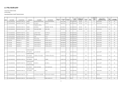
.../COVER/BRAC KET ASSEMBLY EMI SHIELD CASE/COVER/BRAC KET ASSEMBLY STAND NECK(BASE) CASE/COVER/BRAC KET ASSEMBLY HINGE LCD COVER LCD BEZEL A'SSY (ACER) CHASSIS EMI SHIELD STAND NECK(BASE) HINGE FACM871B011 U 4WKS REQUIRED FAAM671A100 U 4WKS REQUIRED FAAM671A100 U 4WKS REQUIRED ECCM8814000 U 4WKS REQUIRED FAAM671C000 U 4WKS REQUIRED ECCM872A000 U ...1004/1010 PCB COMPONENT S IC CS5824 TSSOP-56 LV SA582400100 27 C 2WKS U11 3.30 50 LOCAL SCRAP NO NO A. FRU BOM LIST Product Line: Monitor System Product Family: System Model:ABO_AL722(ET.72202.00X),X=4,5,9.
.../COVER/BRAC KET ASSEMBLY EMI SHIELD CASE/COVER/BRAC KET ASSEMBLY STAND NECK(BASE) CASE/COVER/BRAC KET ASSEMBLY HINGE LCD COVER LCD BEZEL A'SSY (ACER) CHASSIS EMI SHIELD STAND NECK(BASE) HINGE FACM871B011 U 4WKS REQUIRED FAAM671A100 U 4WKS REQUIRED FAAM671A100 U 4WKS REQUIRED ECCM8814000 U 4WKS REQUIRED FAAM671C000 U 4WKS REQUIRED ECCM872A000 U ...1004/1010 PCB COMPONENT S IC CS5824 TSSOP-56 LV SA582400100 27 C 2WKS U11 3.30 50 LOCAL SCRAP NO NO A. FRU BOM LIST Product Line: Monitor System Product Family: System Model:ABO_AL722(ET.72202.00X),X=4,5,9.


