
AL2216W Service Guide
Page 1
Acer AL2216W Service Guide Service guide files and updates are available on the CSD web: for more information, Please refer to http: csd.acer.com.tw 1
Acer AL2216W Service Guide Service guide files and updates are available on the CSD web: for more information, Please refer to http: csd.acer.com.tw 1
AL2216W Service Guide
Page 7
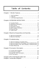
...1 Monitor Features 8 1.1 Test Conditions 8 1.2 Features 8 1.3 LCD Panel Specification 9 Chapter 2 OPERATING INSTRUCTIONS 13 2.1 Function Name 13 2.2 OSD Menu Description 15 2.3 OSD Control 16 2.4 OSD Menu Screen 16 2.5 OSD Function Definition 17 2.6 Plug and Play 18 2.7 Power Saver 18 Chapter 3 Machine Disassembly and Assembly 19 3.1 Machine Disassembly 19 3.2 Machine Assembly 23 Chapter 4 Troubleshooting 27 4.1 Abnormal display Troubleshooting 27 4.2 Abnormal (On/Off, LCD Display, K/B) Troubleshooting...29 4.3 Abnormal (BIOS, OSD, Other Display) Troubleshooting. .30 4.4 Audio...
...1 Monitor Features 8 1.1 Test Conditions 8 1.2 Features 8 1.3 LCD Panel Specification 9 Chapter 2 OPERATING INSTRUCTIONS 13 2.1 Function Name 13 2.2 OSD Menu Description 15 2.3 OSD Control 16 2.4 OSD Menu Screen 16 2.5 OSD Function Definition 17 2.6 Plug and Play 18 2.7 Power Saver 18 Chapter 3 Machine Disassembly and Assembly 19 3.1 Machine Disassembly 19 3.2 Machine Assembly 23 Chapter 4 Troubleshooting 27 4.1 Abnormal display Troubleshooting 27 4.2 Abnormal (On/Off, LCD Display, K/B) Troubleshooting...29 4.3 Abnormal (BIOS, OSD, Other Display) Troubleshooting. .30 4.4 Audio...
AL2216W Service Guide
Page 8
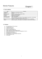
... brightness setting on OSD shall be adjusted to meet 125 nit.) Minolta CS-1000T Spectrometer and Photometer CA-210 or equivalent Before measuring, "Auto Adjust" & "Auto Balance" must be done in advance 1.2 Features 22" wide WSXGA+ TFT LCD Panel TN Mode Liquid Crystal D-SUB/ DVI-D Input Audio Function (Optional) Support to 75Hz Refresh Rate Support VESA-DCC 2B plug & play function Support VESA-DPMS & DVI DMPM Power Management Function Super Wide Viewing Angle High Brightness & Contrast Ratio High Brightness & Contrast Angular...
... brightness setting on OSD shall be adjusted to meet 125 nit.) Minolta CS-1000T Spectrometer and Photometer CA-210 or equivalent Before measuring, "Auto Adjust" & "Auto Balance" must be done in advance 1.2 Features 22" wide WSXGA+ TFT LCD Panel TN Mode Liquid Crystal D-SUB/ DVI-D Input Audio Function (Optional) Support to 75Hz Refresh Rate Support VESA-DCC 2B plug & play function Support VESA-DPMS & DVI DMPM Power Management Function Super Wide Viewing Angle High Brightness & Contrast Ratio High Brightness & Contrast Angular...
AL2216W Service Guide
Page 9
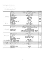
..." wide diagonal) a-si TFT Active Matrix 1680 x R.G.B. msec - - - Vertical Sync. x 1050 0.282 (H) x 0.282 (V) RGB Vertical Stripe 16.2M Normally White Typical 170 / 160 Typical 300 Unit mm - pixel mm color degree cd/m2 Graphic Performance Contrast Ratio LC Response Time (Tr+Tf) Separate Sync. Input Connector Auto Adjust Screen Scaling Power Management Color Adjustment OSD Language Supplier (Model No.) Power Input Input frequency Power source Input Current Efficiency Inrush Current (Cold Start at 25 ,Full Load) Operation Mode Power consumption Power Saving Sleep Mode Power...
..." wide diagonal) a-si TFT Active Matrix 1680 x R.G.B. msec - - - Vertical Sync. x 1050 0.282 (H) x 0.282 (V) RGB Vertical Stripe 16.2M Normally White Typical 170 / 160 Typical 300 Unit mm - pixel mm color degree cd/m2 Graphic Performance Contrast Ratio LC Response Time (Tr+Tf) Separate Sync. Input Connector Auto Adjust Screen Scaling Power Management Color Adjustment OSD Language Supplier (Model No.) Power Input Input frequency Power source Input Current Efficiency Inrush Current (Cold Start at 25 ,Full Load) Operation Mode Power consumption Power Saving Sleep Mode Power...

AL2216W Service Guide
Page 11
... measuring area corner: X=10.0mm ; Horizontal Line Number [pixel] Vertical Line Number [pixel] : test point X (Minolta CA-210) Active area The position of the point X at Figure in Note (5). Y=10.0mm Luminance of Contrast Ratio (CR): The contrast ratio can be calculated by the following expression and figure below. (2) Definition of center point: L=L(1) Brightness Uniformity Measurement points: Thirteen specified points...
... measuring area corner: X=10.0mm ; Horizontal Line Number [pixel] Vertical Line Number [pixel] : test point X (Minolta CA-210) Active area The position of the point X at Figure in Note (5). Y=10.0mm Luminance of Contrast Ratio (CR): The contrast ratio can be calculated by the following expression and figure below. (2) Definition of center point: L=L(1) Brightness Uniformity Measurement points: Thirteen specified points...

AL2216W Service Guide
Page 13
OPERATING INSTRUCTIONS 2.1 Function Name 2.1.1 Front Chapter 2 No. Key Descriptions 1` LED Indicator Green Normal operation Orange Power Management 2 Power on Power off 3 OSD control MENU button/Access Main/Sub-menu/Quick Menu Selection 4 /QUICK MENU Access (Brightness, Contrast and Volume) 5 /QUICK MENU Access (Brightness, Contrast and Volume) 6 Adjust Clock, Phase, H Position and V Position automatically / Exit 7 D-Sub, DVI Input Source Selection/Turbo Brightness Switch 13
OPERATING INSTRUCTIONS 2.1 Function Name 2.1.1 Front Chapter 2 No. Key Descriptions 1` LED Indicator Green Normal operation Orange Power Management 2 Power on Power off 3 OSD control MENU button/Access Main/Sub-menu/Quick Menu Selection 4 /QUICK MENU Access (Brightness, Contrast and Volume) 5 /QUICK MENU Access (Brightness, Contrast and Volume) 6 Adjust Clock, Phase, H Position and V Position automatically / Exit 7 D-Sub, DVI Input Source Selection/Turbo Brightness Switch 13
AL2216W Service Guide
Page 15
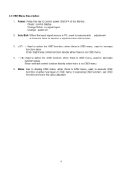
.... Menu: Use to control power ON/OFF of OSD menu; when there is OSD menu, used to execute OSD function or enter next layer of the Monitor. Orange: power off. 2. Enter brightness control function directly when there is OSD menu, used to execute auto adjustment >: Press this key to display OSD menu; Power: Press this button for selection or adjustment when OSD is no signal input. Green: normal display. when there is no OSD menu. 4. / : Used to increase function value. Auto/Exit: When the input signal source...
.... Menu: Use to control power ON/OFF of OSD menu; when there is OSD menu, used to execute OSD function or enter next layer of the Monitor. Orange: power off. 2. Enter brightness control function directly when there is OSD menu, used to execute auto adjustment >: Press this key to display OSD menu; Power: Press this button for selection or adjustment when OSD is no signal input. Green: normal display. when there is no OSD menu. 4. / : Used to increase function value. Auto/Exit: When the input signal source...
AL2216W Service Guide
Page 16
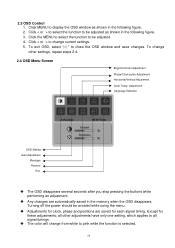
... changes are saved for these adjustments, all signal timings. Turning off the power should be adjusted as shown in the following figure. 3. Click < or > to all other settings, repeat steps 2-4. 2.4 OSD Menu Screen Bright/Contract Adjustment Phase/Clock pulse Adjustment Horizontal/Vertical Adjustment Color Temp. Click MENU to be avoided while using the menu. Click < or > to select the function to display the OSD window as shown in the memory when the OSD disappears. Adjustment Language Selection OSD Setting Auto Adjustment...
... changes are saved for these adjustments, all signal timings. Turning off the power should be adjusted as shown in the following figure. 3. Click < or > to all other settings, repeat steps 2-4. 2.4 OSD Menu Screen Bright/Contract Adjustment Phase/Clock pulse Adjustment Horizontal/Vertical Adjustment Color Temp. Click MENU to be avoided while using the menu. Click < or > to select the function to display the OSD window as shown in the memory when the OSD disappears. Adjustment Language Selection OSD Setting Auto Adjustment...
AL2216W Service Guide
Page 17
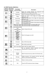
...User Definition/Red User Definition/Green Adjust red/green/blue gain User Definition/Blue N/A English N/A N/A N/A Deutsch Francis Select the language you want (for DVI Input only) N/A Message Display resolution, H/V frequency and the input port used for current input timing function Restore Restore to be warm white color N/A Cold Color Temp. to factory settings N/A Exit Close the OSD window and save changes N/A 17 Set up horizontal, vertical, sequence and focus N/A Auto Adjustment automatically (for analog input only) N/A Analog Digital Select the input source...
...User Definition/Red User Definition/Green Adjust red/green/blue gain User Definition/Blue N/A English N/A N/A N/A Deutsch Francis Select the language you want (for DVI Input only) N/A Message Display resolution, H/V frequency and the input port used for current input timing function Restore Restore to be warm white color N/A Cold Color Temp. to factory settings N/A Exit Close the OSD window and save changes N/A 17 Set up horizontal, vertical, sequence and focus N/A Auto Adjustment automatically (for analog input only) N/A Analog Digital Select the input source...
AL2216W Service Guide
Page 18
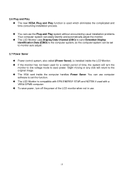
... time-consuming installation process. 2.6 Plug and Play The new VESA Plug and Play function is used with a VESA DPMS computer. Slight moving or any click will turn the monitor to low voltage mode to the computer system, so the computer system can be set the function. You can easily identify and automatically adjust the monitor. The VGA card inside the LCD Monitor. To save power, turn off the power of...
... time-consuming installation process. 2.6 Plug and Play The new VESA Plug and Play function is used with a VESA DPMS computer. Slight moving or any click will turn the monitor to low voltage mode to the computer system, so the computer system can be set the function. You can easily identify and automatically adjust the monitor. The VGA card inside the LCD Monitor. To save power, turn off the power of...
AL2216W Service Guide
Page 19
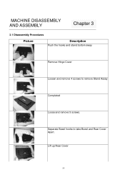
Lift up Rear Cover 19 MACHINE DISASSEMBLY AND ASSEMBLY Chapter 3 3.1 Disassembly Procedures Picture Description Push the hooks and stand bottom away Remove Hinge Cover Loosen and remove 4 screws to take Bezel and Rear Cover Apart. Separate Bezel hooks to remove Stand Assay Completed Loose and remove 5 screws.
Lift up Rear Cover 19 MACHINE DISASSEMBLY AND ASSEMBLY Chapter 3 3.1 Disassembly Procedures Picture Description Push the hooks and stand bottom away Remove Hinge Cover Loosen and remove 4 screws to take Bezel and Rear Cover Apart. Separate Bezel hooks to remove Stand Assay Completed Loose and remove 5 screws.
AL2216W Service Guide
Page 20
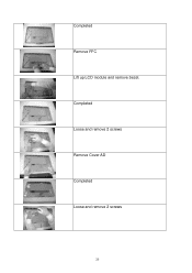
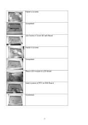
Completed Loose and remove 2 screws Remove Cover AD Completed Loose and remove 2 screws 20 Completed Remove FFC Lift up LCD module and remove bezel.
Completed Loose and remove 2 screws Remove Cover AD Completed Loose and remove 2 screws 20 Completed Remove FFC Lift up LCD module and remove bezel.
AL2216W Service Guide
Page 21
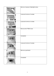
Remove 4 pieces of Backlight wires. Loose and remove 4 screws Loose and remove 2 screws Remove the PCBA Cover Completed Loose and remove 4 screws Remove Lips Board Completed 21
Remove 4 pieces of Backlight wires. Loose and remove 4 screws Loose and remove 2 screws Remove the PCBA Cover Completed Loose and remove 4 screws Remove Lips Board Completed 21
AL2216W Service Guide
Page 22
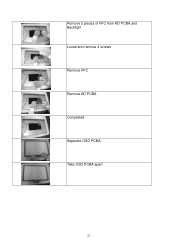
Take OSD PCBA apart 22 Remove 2 pieces of FFC from AD PCBA and Backlight Loose and remove 4 screws Remove FFC Remove AD PCBA Completed Separate OSD PCBA.
Take OSD PCBA apart 22 Remove 2 pieces of FFC from AD PCBA and Backlight Loose and remove 4 screws Remove FFC Remove AD PCBA Completed Separate OSD PCBA.
AL2216W Service Guide
Page 25
Insert a piece of Cover AD with Bezel Fasten 2 screws Completed Place LCD module to OSD Board Completed 25 Fasten 2 screws Completed Join hooks of FFC to LCD Bezel.
Insert a piece of Cover AD with Bezel Fasten 2 screws Completed Place LCD module to OSD Board Completed 25 Fasten 2 screws Completed Join hooks of FFC to LCD Bezel.

AL2216W Service Guide
Page 32
Connector Information 5.1 Function Block Diagram Chapter 5 OSD Key Pad DVI-D Digital Video D-sub Analog Video AC Power Main Board LDO DC-5V DC-13.8V 3.3V 13.8V Signal LCD Module LIPS Backlight 32
Connector Information 5.1 Function Block Diagram Chapter 5 OSD Key Pad DVI-D Digital Video D-sub Analog Video AC Power Main Board LDO DC-5V DC-13.8V 3.3V 13.8V Signal LCD Module LIPS Backlight 32
AL2216W Service Guide
Page 34
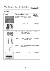
FRU (Field Replaceable Unit) List Chapter 6 Part List Picture Part name Description FUNCTION PCBA FOR ,A190A2BUTTON H,A190A2-H-K2,106BOARD 02,REV.01 Vendor Part No. 35-D003068 Lips Lips Without Audio, 27-D008552 DAC-19M009 BF Main Board PCBA for ,A220Z1-Z01H,A170E2-E03-HS6,1101-01,Rev.04 35-D007790 CABLES FFC,15 Pins, A220Z1- 32-D009095 H02,OSD_FFC CABLE FFC,CFC2128/862P0600 32-D008479 68D,36 Pins MONITOR CABLE Accessory Cable,DSub,BLACK 32F3018003 34
FRU (Field Replaceable Unit) List Chapter 6 Part List Picture Part name Description FUNCTION PCBA FOR ,A190A2BUTTON H,A190A2-H-K2,106BOARD 02,REV.01 Vendor Part No. 35-D003068 Lips Lips Without Audio, 27-D008552 DAC-19M009 BF Main Board PCBA for ,A220Z1-Z01H,A170E2-E03-HS6,1101-01,Rev.04 35-D007790 CABLES FFC,15 Pins, A220Z1- 32-D009095 H02,OSD_FFC CABLE FFC,CFC2128/862P0600 32-D008479 68D,36 Pins MONITOR CABLE Accessory Cable,DSub,BLACK 32F3018003 34
AL2216W Service Guide
Page 35
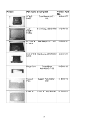
Picture Part name Description STAND BASE Stand Assy,A220Z1H02, Vendor Part No. 40-D009177 LCD FRONT BEZEL Bezel Assy,A220Z1-H02 40-D009188 LCD BACK Rear Assy,A220Z1-H02 40-D009181 COVER LCD STAND Stand Assy,A220Z1-H02 40-D009177 NECK Hinge Cover Cover Hinge Assy,A220Z1-H02 40-D009185 Support Plate Support Plate,A220Z1- 41-D009178 H02 Cover AD Cover AD Assy,A190A2 41-D008025 35
Picture Part name Description STAND BASE Stand Assy,A220Z1H02, Vendor Part No. 40-D009177 LCD FRONT BEZEL Bezel Assy,A220Z1-H02 40-D009188 LCD BACK Rear Assy,A220Z1-H02 40-D009181 COVER LCD STAND Stand Assy,A220Z1-H02 40-D009177 NECK Hinge Cover Cover Hinge Assy,A220Z1-H02 40-D009185 Support Plate Support Plate,A220Z1- 41-D009178 H02 Cover AD Cover AD Assy,A190A2 41-D008025 35
AL2216W Service Guide
Page 37
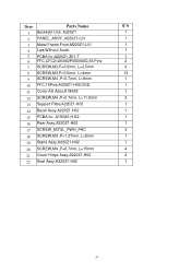
Item Parts Name Q'ty 1 Backlight Unit, A220Z1 1 2 PANEL_ASSY_A220Z1-L01 1 3 Metal Frame Front,M220Z1-L01 1 4 Lips Without Audio 1 5 PCBA for,A220Z1-Z01-T 1 6 FFC,CFC2128/862P060068D,36 Pins 2 7 SCREW,M3,P=0.5mm, L=2.5mm 3 8 SCREW,M3,P=0.5mm, L=4mm 13 9 SCREW,M4 ,P=0.7mm, L=8mm 1 10 FFC,15Pins,A220Z1-H02,OSD 1 11 Cover AD Assy,A190A2 1 12 SCREW,M4 ,P=0.7mm, L=11.8mm 2 13 Support Plate,A220Z1-H02...
Item Parts Name Q'ty 1 Backlight Unit, A220Z1 1 2 PANEL_ASSY_A220Z1-L01 1 3 Metal Frame Front,M220Z1-L01 1 4 Lips Without Audio 1 5 PCBA for,A220Z1-Z01-T 1 6 FFC,CFC2128/862P060068D,36 Pins 2 7 SCREW,M3,P=0.5mm, L=2.5mm 3 8 SCREW,M3,P=0.5mm, L=4mm 13 9 SCREW,M4 ,P=0.7mm, L=8mm 1 10 FFC,15Pins,A220Z1-H02,OSD 1 11 Cover AD Assy,A190A2 1 12 SCREW,M4 ,P=0.7mm, L=11.8mm 2 13 Support Plate,A220Z1-H02...
AL2216W Service Guide
Page 39
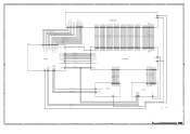
...RX2N RX1P RX1N RX0P RX0N RXCP RXCN RX2P RX2N RX1P RX1N RX0P RX0N RXCP RXCN RX2P RX2N RX1P RX1N RX0P RX0N RXCP RXCN DDC_CLK DDC_DAT CONNECT VGA_5V 01_VGA V18_ESD VSYNC HSYNC GNDB GNDG GNDR SOG BIN GIN RIN VSYNC HSYNC GNDB GNDG GNDR SOG BIN GIN RIN VSYNC HSYNC GNDB ...FR0P FR0N STB POL STV CKV OE VCM_PWM INV_ADJ VOL_ADJ GVOFF GVON FSTHI BSTHI 2 B2 2 1 V5A V33S D C V18_ESD V33S V18_ESD V33S Title A170E2-E03-H-S6(DIAGRAM) DWG NO A1702035S630101 DATE APPROVED CHECKED DESIGNER DRAWER REV "CHI MEI" COPYRIGHT 2000 , ALL RIGHTS RESEREVD, COPYING FORBIDDEN 1 2005/12/08 04 1/6 SHEET B A
...RX2N RX1P RX1N RX0P RX0N RXCP RXCN RX2P RX2N RX1P RX1N RX0P RX0N RXCP RXCN RX2P RX2N RX1P RX1N RX0P RX0N RXCP RXCN DDC_CLK DDC_DAT CONNECT VGA_5V 01_VGA V18_ESD VSYNC HSYNC GNDB GNDG GNDR SOG BIN GIN RIN VSYNC HSYNC GNDB GNDG GNDR SOG BIN GIN RIN VSYNC HSYNC GNDB ...FR0P FR0N STB POL STV CKV OE VCM_PWM INV_ADJ VOL_ADJ GVOFF GVON FSTHI BSTHI 2 B2 2 1 V5A V33S D C V18_ESD V33S V18_ESD V33S Title A170E2-E03-H-S6(DIAGRAM) DWG NO A1702035S630101 DATE APPROVED CHECKED DESIGNER DRAWER REV "CHI MEI" COPYRIGHT 2000 , ALL RIGHTS RESEREVD, COPYING FORBIDDEN 1 2005/12/08 04 1/6 SHEET B A


