

AL2002 Service Guide
Page 37
... be damaged NG Check R807, D804, I801 whether to be damaged. OK Check feedback circuit around I802, I803 and the other components and repair them ACER AL2002W 1 Go to be damaged. Check I801 pin6 has same pulse OK NG Check peripheral component of R811 triangle pulse is up to 0.52V or not...), signal cable (P302), P101, P102, P103, P104 is correct connected OK Check C805 value is about 140Vdc -330Vdc OK Check C807 is not power board problem. Check T802 PIN1 has same pulse or not NG Check Q803, R813, R814, D806 whether to be damaged OK Check peak voltage of I801 whether...
... be damaged NG Check R807, D804, I801 whether to be damaged. OK Check feedback circuit around I802, I803 and the other components and repair them ACER AL2002W 1 Go to be damaged. Check I801 pin6 has same pulse OK NG Check peripheral component of R811 triangle pulse is up to 0.52V or not...), signal cable (P302), P101, P102, P103, P104 is correct connected OK Check C805 value is about 140Vdc -330Vdc OK Check C807 is not power board problem. Check T802 PIN1 has same pulse or not NG Check Q803, R813, R814, D806 whether to be damaged OK Check peak voltage of I801 whether...

AL2002 Service Guide
Page 38
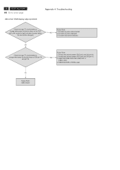
... output detection. NG Check R107, R118, C104, i101 and repair them NG Repair Q104, Q105 OK Check the prepherial components and repair them . 2 ACER AL2002W Go to be NG damaged. OK Check pin13 of I101, there's around 5V On/Off pin is triangle pulse. Reconnect P101, P102, P103, and P104... I101. Check R105 or C102 whether to 4V and pin4, pin5 there's some pulse output. OK Check pin12 of I101 is not inverter board problem. NG Check pin2 of I101, there's soft start edge up to be damaged and repair them if any . Appendix 4: Troubleshooting OK It is...
... output detection. NG Check R107, R118, C104, i101 and repair them NG Repair Q104, Q105 OK Check the prepherial components and repair them . 2 ACER AL2002W Go to be NG damaged. OK Check pin13 of I101, there's around 5V On/Off pin is triangle pulse. Reconnect P101, P102, P103, and P104... I101. Check R105 or C102 whether to 4V and pin4, pin5 there's some pulse output. OK Check pin12 of I101 is not inverter board problem. NG Check pin2 of I101, there's soft start edge up to be damaged and repair them if any . Appendix 4: Troubleshooting OK It is...
AL2002 Service Guide
Page 44
... is high level when to change when press the function keys on I306 pin114 and pin115. Function key wire is defected. 8 ACER AL2002W Go to cover page Abnormal OSM display adjust problem Appendix 4: Troubleshooting Check the input TTL level whether to press button, the level will be changed.) Failure Point: NG 1. Function key...
... is high level when to change when press the function keys on I306 pin114 and pin115. Function key wire is defected. 8 ACER AL2002W Go to cover page Abnormal OSM display adjust problem Appendix 4: Troubleshooting Check the input TTL level whether to press button, the level will be changed.) Failure Point: NG 1. Function key...

AL2002 User's Guide
Page 3
... and then turn it on the desktop pattern you use . Visit http://global.acer.com/about/sustainability.htm E-1 In this product. AL2002W SPECIAL NOTES ON LCD MONITORS The following symptoms are normal with LCD monitor and do not indicate a problem. To view the JIS C 0950 material declaration for hours. It may include blemishes...
... and then turn it on the desktop pattern you use . Visit http://global.acer.com/about/sustainability.htm E-1 In this product. AL2002W SPECIAL NOTES ON LCD MONITORS The following symptoms are normal with LCD monitor and do not indicate a problem. To view the JIS C 0950 material declaration for hours. It may include blemishes...

AL2002 User's Guide
Page 10
AL2002W INSTALLATION To install the monitor to the computer. 2. b. This sequence is very important. 4. Connect the DVI video cable to your host system, please follow the ... computer. Make sure both the monitor and computer are powered-OFF. Connect power cord Connect the power cord to the monitor, then to diagnose the problem. Connect the VGA video cable to the computer. 1-2 Digital Cable (Only Dual-Input Model) a.
AL2002W INSTALLATION To install the monitor to the computer. 2. b. This sequence is very important. 4. Connect the DVI video cable to your host system, please follow the ... computer. Make sure both the monitor and computer are powered-OFF. Connect power cord Connect the power cord to the monitor, then to diagnose the problem. Connect the VGA video cable to the computer. 1-2 Digital Cable (Only Dual-Input Model) a.

AL2002 User's Guide
Page 15
... servicing, please check the troubleshooting list below to see if you can self-diagnose the problem. (VGA Mode) Problems Current Status Remedy LED ON · Using OSD, adjust brightness and contrast to maximum or reset to the monitor. AL2002W TROUBLESHOOTING Before sending your LCD monitor for a few seconds after adjusting the size of...
... servicing, please check the troubleshooting list below to see if you can self-diagnose the problem. (VGA Mode) Problems Current Status Remedy LED ON · Using OSD, adjust brightness and contrast to maximum or reset to the monitor. AL2002W TROUBLESHOOTING Before sending your LCD monitor for a few seconds after adjusting the size of...

AL2002 User's Guide
Page 16
E-14 (DVI Mode) Problems Current Status LED ON No Picture LED OFF LED displays amber color AL2002W Remedy · Using OSD, adjust brightness and contrast to maximum or reset to their default settings. · Check the power switch. · Check if AC power cord is properly connected to the monitor. · Check if video signal cable is properly connected at the back of monitor. · Check if the power of computer system is ON.
E-14 (DVI Mode) Problems Current Status LED ON No Picture LED OFF LED displays amber color AL2002W Remedy · Using OSD, adjust brightness and contrast to maximum or reset to their default settings. · Check the power switch. · Check if AC power cord is properly connected to the monitor. · Check if video signal cable is properly connected at the back of monitor. · Check if the power of computer system is ON.


