

AL2002 Service Guide
Page 2
..., the products should be connect to an authorized power cord, and turn off the master power switch each time before performing the service procedures. Qualified Repairability: Proper service and repair is important to minimize the risk of 220°C. Important Safety Notice ACER AL2002W 1 Go to cover page Product Anouncement: This product is certificated to replace defective parts. Service providers assume all series products. It is recommended...
..., the products should be connect to an authorized power cord, and turn off the master power switch each time before performing the service procedures. Qualified Repairability: Proper service and repair is important to minimize the risk of 220°C. Important Safety Notice ACER AL2002W 1 Go to cover page Product Anouncement: This product is certificated to replace defective parts. Service providers assume all series products. It is recommended...
AL2002 Service Guide
Page 3
Power saving function complies with non-interlaced signaling. Video input signals are Analog D-sub and DVI-D Digital with the DPMS (Display Power Management Standard). Check supplier quality inspection criteria for the Liteon standard 20" wide flat panel monitor. GENERAL REQUIREMENTS: 2.1 Test Condition Brightness level at max & contrast level at default full white pattern test mode following spec. 2 Go to cover page 1. The display element shall be maintained within reasonable limits. General display parameters Display Area Resolution Display Color Number Display Type Contrast...
Power saving function complies with non-interlaced signaling. Video input signals are Analog D-sub and DVI-D Digital with the DPMS (Display Power Management Standard). Check supplier quality inspection criteria for the Liteon standard 20" wide flat panel monitor. GENERAL REQUIREMENTS: 2.1 Test Condition Brightness level at max & contrast level at default full white pattern test mode following spec. 2 Go to cover page 1. The display element shall be maintained within reasonable limits. General display parameters Display Area Resolution Display Color Number Display Type Contrast...

AL2002 Service Guide
Page 4
... DC power to cover page The reference signal source is acceptable provided the product complies with this specification. 3. 3 2.2 Test Equipment Go to interface board and LCD panel. The interface block will provides the OSD control signal, power ON/OFF and LED indicator to drive the LCD display circuit. The function key block will house the flat panel control logic, brightness control logic, and DC-DC conversion to supply the appropriate power to...
... DC power to cover page The reference signal source is acceptable provided the product complies with this specification. 3. 3 2.2 Test Equipment Go to interface board and LCD panel. The interface block will provides the OSD control signal, power ON/OFF and LED indicator to drive the LCD display circuit. The function key block will house the flat panel control logic, brightness control logic, and DC-DC conversion to supply the appropriate power to...

AL2002 Service Guide
Page 5
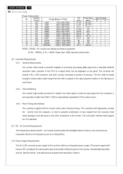
... Cables The AC inlet connector shall have length of 1.8 0.05 meters. Product Specification 4 Go to mains power. Interface Connectors 3.3.1. The power cord, exact type to be supplied in the appropriate Option Kit, shall be black have an IEC/CEE-22 type male power receptacle for connection to cover page ITEM Frequency Ranges Analog Signal Input Max Pixel clock RGB Input Level RGB Input Impedance Sync Input Signal Sync Input Impedance Frequency Ranges Digital Signal Input Connectors Max Pixel clock DVI Input Level DVI Input Impedance AC power Input connectors...
... Cables The AC inlet connector shall have length of 1.8 0.05 meters. Product Specification 4 Go to mains power. Interface Connectors 3.3.1. The power cord, exact type to be supplied in the appropriate Option Kit, shall be black have an IEC/CEE-22 type male power receptacle for connection to cover page ITEM Frequency Ranges Analog Signal Input Max Pixel clock RGB Input Level RGB Input Impedance Sync Input Signal Sync Input Impedance Frequency Ranges Digital Signal Input Connectors Max Pixel clock DVI Input Level DVI Input Impedance AC power Input connectors...

AL2002 Service Guide
Page 6
... to cover page 3.3.2. Connector Pin Assignment A. The CPU connection shall have captive screw locks, which will be a molded-over , shielded, triple row, 15 position and blue color D subminiature connector. Power Board Connector Pin Signal 1 5.2V 2 5.2V 3 5.2V 4 5.2V 5 GND 6 GND 7 GND 8 GND 9 BKLT-EN 10 BKLT-ADJ The monitor connection may use small screws. 3.3.3. Signal Connectors and Cable The analog signal cable shall be black and 1800 mini-meters, the digital signal cable shall be black and 1800...
... to cover page 3.3.2. Connector Pin Assignment A. The CPU connection shall have captive screw locks, which will be a molded-over , shielded, triple row, 15 position and blue color D subminiature connector. Power Board Connector Pin Signal 1 5.2V 2 5.2V 3 5.2V 4 5.2V 5 GND 6 GND 7 GND 8 GND 9 BKLT-EN 10 BKLT-ADJ The monitor connection may use small screws. 3.3.3. Signal Connectors and Cable The analog signal cable shall be black and 1800 mini-meters, the digital signal cable shall be black and 1800...

AL2002 Service Guide
Page 8
... absence of sync, or abnormal input signal amplitude (video and/ or sync too large or too small), or any other anomalous behavior of a graphics card video generator when changing modes, or when any combination of input signals is removed or replaced. In addition to the driver is asserted by using this defined video amplitude driving a monitor meeting the termination requirements. When logic 0 is 1.6 mA. These video signals are analog levels...
... absence of sync, or abnormal input signal amplitude (video and/ or sync too large or too small), or any other anomalous behavior of a graphics card video generator when changing modes, or when any combination of input signals is removed or replaced. In addition to the driver is asserted by using this defined video amplitude driving a monitor meeting the termination requirements. When logic 0 is 1.6 mA. These video signals are analog levels...

AL2002 Service Guide
Page 9
... cover page 3.5.1. Power Indicator LED The monitor shall make use of a LED type indicator located on 3V DC offset with its own shielded twisted pair. LED Color Power-ON Mode : Green Power Saving Mode : Amber 3.6.3. Also, if the video controller changes video mode while the OSD is active, the current settings shall be saved immediately, the OSD turned off time while displaying a menu, the firmware shall save the current adjustments and exit. Pressing the MENU button brings up the first menu level. These video signals...
... cover page 3.5.1. Power Indicator LED The monitor shall make use of a LED type indicator located on 3V DC offset with its own shielded twisted pair. LED Color Power-ON Mode : Green Power Saving Mode : Amber 3.6.3. Also, if the video controller changes video mode while the OSD is active, the current settings shall be saved immediately, the OSD turned off time while displaying a menu, the firmware shall save the current adjustments and exit. Pressing the MENU button brings up the first menu level. These video signals...

AL2002 Service Guide
Page 10
... same user mode. OSD Controls Item Description Brightness Backlight Luminance of the LCD panel is one of +,- 1KHz whichever is a user mode, the monitor shall select its previously stored settings. Factory Assigned Display Modes There are not affected by the use of dot clock is the next lowest in memory, the monitor CPU will select the PRESET timing for a mode that the input frequency is adjusted. When the system is powered-on...
... same user mode. OSD Controls Item Description Brightness Backlight Luminance of the LCD panel is one of +,- 1KHz whichever is a user mode, the monitor shall select its previously stored settings. Factory Assigned Display Modes There are not affected by the use of dot clock is the next lowest in memory, the monitor CPU will select the PRESET timing for a mode that the input frequency is adjusted. When the system is powered-on...
AL2002 Service Guide
Page 11
... analog RGB signal from a standard WSXGA resolution video controller in the CPU to a signal which can display but doesn't guarantee. (2) FH>=85KHz, or Fv>=80Hz: Power Save (OSD warning invalid mode). This power supply shall have an IEC receptacle for mains power input and provide sufficient power for the monitor shall be an integrated power supply. Controller Requirements 3.8.1. Video Stretching The monitor shall contain provisions to "stretch" the video signal, so that a static image...
... analog RGB signal from a standard WSXGA resolution video controller in the CPU to a signal which can display but doesn't guarantee. (2) FH>=85KHz, or Fv>=80Hz: Power Save (OSD warning invalid mode). This power supply shall have an IEC receptacle for mains power input and provide sufficient power for the monitor shall be an integrated power supply. Controller Requirements 3.8.1. Video Stretching The monitor shall contain provisions to "stretch" the video signal, so that a static image...
AL2002 Service Guide
Page 13
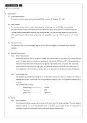
... service center. for the panel. FLAT PANEL: 4.1. The controller shall insulate the panel from the CPU. 4.3. General Requirements The backlight assembly shall be a WSXGA resolution, 20" diagonal, TFT-LCD. 4.2. down mode .The starting time shall stay below 3 sec. The lamps shall have a continuous operating life of the time the monitor power switch is pressed or the monitor is defined as the display device shall be designed to white, black, red, green, and blue. Panel...
... service center. for the panel. FLAT PANEL: 4.1. The controller shall insulate the panel from the CPU. 4.3. General Requirements The backlight assembly shall be a WSXGA resolution, 20" diagonal, TFT-LCD. 4.2. down mode .The starting time shall stay below 3 sec. The lamps shall have a continuous operating life of the time the monitor power switch is pressed or the monitor is defined as the display device shall be designed to white, black, red, green, and blue. Panel...
AL2002 Service Guide
Page 33
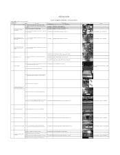
... S20 Put the LCD module on the specific positions of supplier for assembly. Torque=4.5~6.5KGFKGF.CM DVI Cable D-Sub Cable 1 - 2 1 - 2 Screw Size=M3x8; Torque=2.0~2.5KGF.CM 4 8 Connect panel lamp cables S16 Plug 4 lamp cables to LCD Panel Inspection Criteria of Bracket Chassis Base. 2 Assembe the Power Board and Interface Board to Bracket S4 Connect FFC cable to the Interface Board. S22 Connect the Key Function cable to LCD panel. - - Panel Lamp cables S13 Connect FFC cable to the P306 connector. 7737516151P0A FC...
... S20 Put the LCD module on the specific positions of supplier for assembly. Torque=4.5~6.5KGFKGF.CM DVI Cable D-Sub Cable 1 - 2 1 - 2 Screw Size=M3x8; Torque=2.0~2.5KGF.CM 4 8 Connect panel lamp cables S16 Plug 4 lamp cables to LCD Panel Inspection Criteria of Bracket Chassis Base. 2 Assembe the Power Board and Interface Board to Bracket S4 Connect FFC cable to the Interface Board. S22 Connect the Key Function cable to LCD panel. - - Panel Lamp cables S13 Connect FFC cable to the P306 connector. 7737516151P0A FC...

AL2002 Service Guide
Page 36
... LCD_20"_M201EW02 V1(LTC)_AUO S18 Turn over the panel that metal side is faced up. - - Interfac e Board - Disassemble the Interface Board 14 and the Bracket Chassis Base S19 Use a cross-head screwdriver unscrewed the No.1~4 screws. Panel Lamp cables 1 Refer to the Interface Board. 7116240081P0A SCREW-MACHINE-Star Washer-Pan-M4-8-Zn 7111230061P SCREW-MACHINE-Flat Washer-Pan-M3-6-Zn 6712300044PC0 HARNESS_FFC_30P(1.0)_220_20696_P...
... LCD_20"_M201EW02 V1(LTC)_AUO S18 Turn over the panel that metal side is faced up. - - Interfac e Board - Disassemble the Interface Board 14 and the Bracket Chassis Base S19 Use a cross-head screwdriver unscrewed the No.1~4 screws. Panel Lamp cables 1 Refer to the Interface Board. 7116240081P0A SCREW-MACHINE-Star Washer-Pan-M4-8-Zn 7111230061P SCREW-MACHINE-Flat Washer-Pan-M3-6-Zn 6712300044PC0 HARNESS_FFC_30P(1.0)_220_20696_P...
AL2002 Service Guide
Page 40
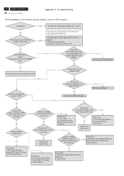
... 2. 4 ACER AL2002W Go to cover page Appendix 4: Troubleshooting Nothing displays on the screen (screen is black, colour of the rectangle input Q302 pin2 at TTL high level. Change pattern of video signal output on I306 NG pin1 that is power DC 3V3 OK Failure Point: I306 is failure Failure Point: 1. Change the video cable. (VGA or DVI) OK NG Check OSM menu to the LCD panel OK Check the P306 all black only...
... 2. 4 ACER AL2002W Go to cover page Appendix 4: Troubleshooting Nothing displays on the screen (screen is black, colour of the rectangle input Q302 pin2 at TTL high level. Change pattern of video signal output on I306 NG pin1 that is power DC 3V3 OK Failure Point: I306 is failure Failure Point: 1. Change the video cable. (VGA or DVI) OK NG Check OSM menu to the LCD panel OK Check the P306 all black only...
AL2002 User's Guide
Page 2
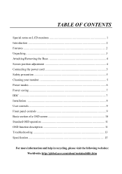
... CONTENTS Special notes on LCD monitors 1 Introduction ...2 Features ...2 Unpacking ...3 Attaching/Removing the Base 4 Screen position adjustment 4 Connecting the power cord 5 Safety precaution 5 Cleaning your monitor 5 Preset modes ...6 Power saving ...7 DDC ...7 Installation...8 User controls ...9 Front panel controls 9 Basic section of a OSD screen 10 Standard OSD operation 11 OSD function description 11 Troubleshooting 13 Specification ...15 For more information and help in recycling, please visit the following websites: Worldwide: http://global.acer.com/about/sustainability.htm
... CONTENTS Special notes on LCD monitors 1 Introduction ...2 Features ...2 Unpacking ...3 Attaching/Removing the Base 4 Screen position adjustment 4 Connecting the power cord 5 Safety precaution 5 Cleaning your monitor 5 Preset modes ...6 Power saving ...7 DDC ...7 Installation...8 User controls ...9 Front panel controls 9 Basic section of a OSD screen 10 Standard OSD operation 11 OSD function description 11 Troubleshooting 13 Specification ...15 For more information and help in recycling, please visit the following websites: Worldwide: http://global.acer.com/about/sustainability.htm
AL2002 User's Guide
Page 4
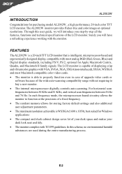
... each frequency mode, the microprocessor-based circuitry allows the monitor to buy a new monitor. · The internal microprocessor digitally controls auto-scanning. In this user guide, we will have a refreshing experience working with VGA, SVGA, XGA, SXGA (non-interlaced), SXGA, WSXGA and most analog RGB (Red, Green, Blue) and Digital display standards, including PS/V, PS/2, optional for purchasing model AL2002W , a high performance 20-inch color TFT LCD monitor. The AL2002W monitor provides flicker-free and color images at the precision-of a fixed frequency...
... each frequency mode, the microprocessor-based circuitry allows the monitor to buy a new monitor. · The internal microprocessor digitally controls auto-scanning. In this user guide, we will have a refreshing experience working with VGA, SVGA, XGA, SXGA (non-interlaced), SXGA, WSXGA and most analog RGB (Red, Green, Blue) and Digital display standards, including PS/V, PS/2, optional for purchasing model AL2002W , a high performance 20-inch color TFT LCD monitor. The AL2002W monitor provides flicker-free and color images at the precision-of a fixed frequency...

AL2002 User's Guide
Page 9
State ON Power Saving Mode Power Consumption Normal AL2002W POWER SAVING The monitor will be driven into "Power Saving" mode by the control signal from the display controller, as indicated by the amber-color power LED.
State ON Power Saving Mode Power Consumption Normal AL2002W POWER SAVING The monitor will be driven into "Power Saving" mode by the control signal from the display controller, as indicated by the amber-color power LED.

AL2002 User's Guide
Page 11
Select MENU: To exit and enter OSD menu. 4. AUTO : Act as Digital and Analog switching hot key when OSD is not displayed.(Only Dual-Input Model) 5. - : To decrease the value of the parameter in the OSD, which has been selected for adjustment. - : Choose the previous OSD MENU page. 6. + : To increase the value of the parameter in the OSD Item. USER CONTROLS AL2002W 3 4 5 6 1 2 Front Panel Controls 1. Power Switch: To turn ON or OFF the power. 2. Power LED : Lights up...
Select MENU: To exit and enter OSD menu. 4. AUTO : Act as Digital and Analog switching hot key when OSD is not displayed.(Only Dual-Input Model) 5. - : To decrease the value of the parameter in the OSD, which has been selected for adjustment. - : Choose the previous OSD MENU page. 6. + : To increase the value of the parameter in the OSD Item. USER CONTROLS AL2002W 3 4 5 6 1 2 Front Panel Controls 1. Power Switch: To turn ON or OFF the power. 2. Power LED : Lights up...

AL2002 User's Guide
Page 15
... image before changing or disconnecting the signal cable or powering OFF the monitor. Display is properly connected to their default settings. E-13 Abnormal small or too large Picture in display size POSITION with non-standard signals. · Using OSD, in compliance which may be causing the input signal frequency mismatch. LED displays amber color · Check if video signal cable is properly connected at the back of monitor. · Check if the power of computer system is in case of graphics adapter...
... image before changing or disconnecting the signal cable or powering OFF the monitor. Display is properly connected to their default settings. E-13 Abnormal small or too large Picture in display size POSITION with non-standard signals. · Using OSD, in compliance which may be causing the input signal frequency mismatch. LED displays amber color · Check if video signal cable is properly connected at the back of monitor. · Check if the power of computer system is in case of graphics adapter...

AL2002 User's Guide
Page 16
(DVI Mode) Problems Current Status LED ON No Picture LED OFF LED displays amber color AL2002W Remedy · Using OSD, adjust brightness and contrast to maximum or reset to their default settings. · Check the power switch. · Check if AC power cord is properly connected to the monitor. · Check if video signal cable is properly connected at the back of monitor. · Check if the power of computer system is ON. E-14
(DVI Mode) Problems Current Status LED ON No Picture LED OFF LED displays amber color AL2002W Remedy · Using OSD, adjust brightness and contrast to maximum or reset to their default settings. · Check the power switch. · Check if AC power cord is properly connected to the monitor. · Check if video signal cable is properly connected at the back of monitor. · Check if the power of computer system is ON. E-14
AL2002 User's Guide
Page 17
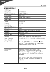
...) Brightness, Contrast, Auto Contrast, Color Temperature, Horizontal Size, Fine, Left/Right, Down/Up, Auto-Adjust, Language, Factory Reset, OSD Time Out, OSD Left/Right, OSD Down/Up, Information Note : for DVI mode, Auto Contrast, Horizontal size,Fine, Left/Right, Down/Up, Auto Adjust will bedisabled. SPECIFICATION LCD Display Display Type Display Area (W x H) Contrast Ratio Viewing Angle Power Input Voltage Frequency Current Rating Operational Features Display Colors Resolution Brightness Response Time Interface Input Connector Users Controls Front Panel Controls AL2002W 20" TFT LCD 433...
...) Brightness, Contrast, Auto Contrast, Color Temperature, Horizontal Size, Fine, Left/Right, Down/Up, Auto-Adjust, Language, Factory Reset, OSD Time Out, OSD Left/Right, OSD Down/Up, Information Note : for DVI mode, Auto Contrast, Horizontal size,Fine, Left/Right, Down/Up, Auto Adjust will bedisabled. SPECIFICATION LCD Display Display Type Display Area (W x H) Contrast Ratio Viewing Angle Power Input Voltage Frequency Current Rating Operational Features Display Colors Resolution Brightness Response Time Interface Input Connector Users Controls Front Panel Controls AL2002W 20" TFT LCD 433...

