

AL2002 Service Guide
Page 39
When a signal is connected normally. (VGA or DVI) OK Proceed to 'Checking the resolution change the cable (VGA or DVI) It indicates with 'Out of Range' at the YES time of computer or change IC movement' section NG Proceed ... the video cable is not being input, it cannot distinguished. Appendix 4: Troubleshooting No display on the screen (Screen is black, colour of LED is amber.) ACER AL2002W 3 Go to 'No OSM display' section NG Input the sync signal of the frequency that it indicates with 'VIDEO INPUT'.
When a signal is connected normally. (VGA or DVI) OK Proceed to 'Checking the resolution change the cable (VGA or DVI) It indicates with 'Out of Range' at the YES time of computer or change IC movement' section NG Proceed ... the video cable is not being input, it cannot distinguished. Appendix 4: Troubleshooting No display on the screen (Screen is black, colour of LED is amber.) ACER AL2002W 3 Go to 'No OSM display' section NG Input the sync signal of the frequency that it indicates with 'VIDEO INPUT'.

AL2002 Service Guide
Page 42
OK Proceed 'Checking the resolution changed IC movement' section Failure Point: In the case of video connector Failure Point: NG 1. Printed wire broke between I306 and P306. l306 is damaged. 4.... VGA R.G.B input video signals on I306 pin99, pin96, pin93 respectively that their level is open between I302 pin1, pin2, pin3 and I306 pin93, pin96, pin99. 6 ACER AL2002W Go to P306 from computer input on P302 of the RED signal. (Green and Blue signals are the same path, too.) 1. NG 2. Failure Point: NG...
OK Proceed 'Checking the resolution changed IC movement' section Failure Point: In the case of video connector Failure Point: NG 1. Printed wire broke between I306 and P306. l306 is damaged. 4.... VGA R.G.B input video signals on I306 pin99, pin96, pin93 respectively that their level is open between I302 pin1, pin2, pin3 and I306 pin93, pin96, pin99. 6 ACER AL2002W Go to P306 from computer input on P302 of the RED signal. (Green and Blue signals are the same path, too.) 1. NG 2. Failure Point: NG...

AL2002 Service Guide
Page 43
...: NG Printed wire is 150mV to cover page Check the TMDS signal from host computer. I306 is failure. 2. OK Proceed 'Checking the resolution changed IC movement' section No TMDS signals output from computer input P303 of the RX2+ signal (A RX1, 0, and RXC signal is disconnected.... Appendix 4: Troubleshooting Abnormal Screen: Abnormal screen for DVI-D source ACER AL2002W 7 Go to 1200mV OK Failure Point: In the case of DVI-D video connector Failure Point: NG 1. DVI-D video signal cable is same path...
...: NG Printed wire is 150mV to cover page Check the TMDS signal from host computer. I306 is failure. 2. OK Proceed 'Checking the resolution changed IC movement' section No TMDS signals output from computer input P303 of the RX2+ signal (A RX1, 0, and RXC signal is disconnected.... Appendix 4: Troubleshooting Abnormal Screen: Abnormal screen for DVI-D source ACER AL2002W 7 Go to 1200mV OK Failure Point: In the case of DVI-D video connector Failure Point: NG 1. DVI-D video signal cable is same path...

AL2002 Service Guide
Page 47
...2. Printed wire is open . 3. FB312 and R322 may be open between P302 pin14 and I306 NG pin90. 2. OK Proceed 'Checking the resolution change IC movement' section Checking the control circuit of horizontal sync pulse for DVI-D Check the horizontal sync signal on P302 pin13 TTL level Failure... Point: NG VGA Video cable is short. R323 and C327 may be short. 4. OK Proceed 'Checking the resolution change IC movement' section Checking the TMDS signal input for DVI-D ACER AL2002W 11 Go to cover page Check the TMDS signal P303 pin1, pin2, pin9, pin10, pin17, pin18, pin23,...
...2. Printed wire is open . 3. FB312 and R322 may be open between P302 pin14 and I306 NG pin90. 2. OK Proceed 'Checking the resolution change IC movement' section Checking the control circuit of horizontal sync pulse for DVI-D Check the horizontal sync signal on P302 pin13 TTL level Failure... Point: NG VGA Video cable is short. R323 and C327 may be short. 4. OK Proceed 'Checking the resolution change IC movement' section Checking the TMDS signal input for DVI-D ACER AL2002W 11 Go to cover page Check the TMDS signal P303 pin1, pin2, pin9, pin10, pin17, pin18, pin23,...

AL2002 Service Guide
Page 48
12 ACER AL2002W Go to I306 pin108 and pin109 at normal operation. pin110, pin116 2. Check +1V8 supplied on I309 pin8. C362 or C373 may be short or open . ... DC/DC converter circuit' section Failure Point: 1. R349, R348 is short. 3. OK Check X301 14.318MHz clock input to cover page Appendix 4: Troubleshooting Checking the resolution change IC movement 1. OK Failure Point: I306 is high level at TTL level OK Check I306 pin111 RSTB signal is defected. R362,R364,R365,R366...
12 ACER AL2002W Go to I306 pin108 and pin109 at normal operation. pin110, pin116 2. Check +1V8 supplied on I309 pin8. C362 or C373 may be short or open . ... DC/DC converter circuit' section Failure Point: 1. R349, R348 is short. 3. OK Check X301 14.318MHz clock input to cover page Appendix 4: Troubleshooting Checking the resolution change IC movement 1. OK Failure Point: I306 is high level at TTL level OK Check I306 pin111 RSTB signal is defected. R362,R364,R365,R366...
AL2002 User's Guide
Page 4
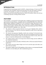
... fixed frequency. · The resident memory allows for storing factory default settings and also additional user adjustment parameters. · The maximum resolution achievable is able to buy a new monitor. · The internal microprocessor digitally controls auto-scanning. Through this scheme, no environmental harmful ... with TCO99 guidelines. In each frequency mode, the microprocessor-based circuitry allows the monitor to function at optional resolutions. AL2002W INTRODUCTION Congratulations for purchasing model AL2002W , a high performance 20-inch color TFT LCD monitor.
... fixed frequency. · The resident memory allows for storing factory default settings and also additional user adjustment parameters. · The maximum resolution achievable is able to buy a new monitor. · The internal microprocessor digitally controls auto-scanning. Through this scheme, no environmental harmful ... with TCO99 guidelines. In each frequency mode, the microprocessor-based circuitry allows the monitor to function at optional resolutions. AL2002W INTRODUCTION Congratulations for purchasing model AL2002W , a high performance 20-inch color TFT LCD monitor.

AL2002 User's Guide
Page 8
... different from the default modes. For optimum adjustment, the user is matched, the user can store their preferred modes in the floppy disk provided. Mode Resolution H. When none of storing up to 9 user modes. Freq. (KHz) 1 VGA 720 x 400 70 Hz 31.47 2 VGA 640 x 480 60 Hz 31.47 3 VESA... 1680 x 1050 60 Hz 65.3 Band Width (MHz) 28.322 25.175 31.5 40 49.5 65 78.75 108 108 135 146.25 Polarity HV E-6 AL2002W PRESET MODES To reduce the need for adjustment for vertical frequency or the sync signal polarities are most commonly used as a user mode is capable...
... different from the default modes. For optimum adjustment, the user is matched, the user can store their preferred modes in the floppy disk provided. Mode Resolution H. When none of storing up to 9 user modes. Freq. (KHz) 1 VGA 720 x 400 70 Hz 31.47 2 VGA 640 x 480 60 Hz 31.47 3 VESA... 1680 x 1050 60 Hz 65.3 Band Width (MHz) 28.322 25.175 31.5 40 49.5 65 78.75 108 108 135 146.25 Polarity HV E-6 AL2002W PRESET MODES To reduce the need for adjustment for vertical frequency or the sync signal polarities are most commonly used as a user mode is capable...

AL2002 User's Guide
Page 9
AL2002W POWER SAVING The monitor will be driven into "Power Saving" mode by the control signal from the display controller, as indicated by the amber-color power LED. State ON Power Saving Mode Power Consumption Normal
AL2002W POWER SAVING The monitor will be driven into "Power Saving" mode by the control signal from the display controller, as indicated by the amber-color power LED. State ON Power Saving Mode Power Consumption Normal

AL2002 User's Guide
Page 14
AL2002W · Auto Adjust Press "+" to turn -off time. · OSD Left / Right To move the OSD position horizontally on the screen. When the "+" key is ... settings. · OSD TimeOut To adjust the period of the screen. The Auto-Adjust will move to the lower side. · Information Indicates the current resolution and V-Frequency. Likewise when the "-" key is pressed, the OSD control menu will automatically adjust V-Position, H-Position, Clock, and Clock-Phase, the whole process takes...
AL2002W · Auto Adjust Press "+" to turn -off time. · OSD Left / Right To move the OSD position horizontally on the screen. When the "+" key is ... settings. · OSD TimeOut To adjust the period of the screen. The Auto-Adjust will move to the lower side. · Information Indicates the current resolution and V-Frequency. Likewise when the "-" key is pressed, the OSD control menu will automatically adjust V-Position, H-Position, Clock, and Clock-Phase, the whole process takes...

AL2002 User's Guide
Page 15
AL2002W TROUBLESHOOTING Before sending your LCD monitor for a few seconds after adjusting the size of the image before changing or disconnecting the signal cable or powering OFF the monitor. No Picture · Check if AC power cord is missing, · Using OSD, adjust RESOLUTION, CLOCK, center shift,...ON. Unstable Picture · Check if the specification of computer system is in case of missing full-screen image, please select other resolution or other vertical refresh timing. · Wait for servicing, please check the troubleshooting list below to see if you can self-diagnose...
AL2002W TROUBLESHOOTING Before sending your LCD monitor for a few seconds after adjusting the size of the image before changing or disconnecting the signal cable or powering OFF the monitor. No Picture · Check if AC power cord is missing, · Using OSD, adjust RESOLUTION, CLOCK, center shift,...ON. Unstable Picture · Check if the specification of computer system is in case of missing full-screen image, please select other resolution or other vertical refresh timing. · Wait for servicing, please check the troubleshooting list below to see if you can self-diagnose...
AL2002 User's Guide
Page 17
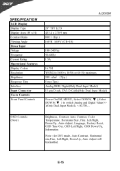
... LCD Display Display Type Display Area (W x H) Contrast Ratio Viewing Angle Power Input Voltage Frequency Current Rating Operational Features Display Colors Resolution Brightness Response Time Interface Input Connector Users Controls Front Panel Controls AL2002W 20" TFT LCD 433.4 x 270.9 mm 800:1 (Typ.) 160oH 160oV (CR=10) 100-240Vac 50-60Hz 1.5A 16.7M...
... LCD Display Display Type Display Area (W x H) Contrast Ratio Viewing Angle Power Input Voltage Frequency Current Rating Operational Features Display Colors Resolution Brightness Response Time Interface Input Connector Users Controls Front Panel Controls AL2002W 20" TFT LCD 433.4 x 270.9 mm 800:1 (Typ.) 160oH 160oV (CR=10) 100-240Vac 50-60Hz 1.5A 16.7M...


