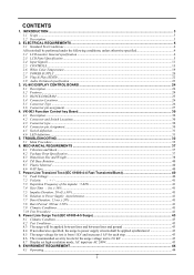
AL1731 Service Guide
Page 2
... is 2.0 KV 43 8.7 Display set high-resolution mode, AC input use AC 240V 43 9. ENVIROMENT REQUIREMENT...44 9.1 Operating...44 1 Power Line Surge Test (IEC 61000-4-5 Surge 43 8.1 Climatic Condition ...43 8.2 Test Conditions:...43 8.3 The surge will be performed under the following conditions, unless otherwise specified 4 2.2 LCD monitor General specification ...4 2.3 LCD Panel Specification ...5 2.4 Input Signals...11 2.5 CONTROLS ...15 2.6 White Color Temperature...19 2.7 POWER SUPPLY ...20 2.8 Plug & Play (EDID) ...22 2.9 Audio Technical specification ...23 3. INTRODUCTION...
... is 2.0 KV 43 8.7 Display set high-resolution mode, AC input use AC 240V 43 9. ENVIROMENT REQUIREMENT...44 9.1 Operating...44 1 Power Line Surge Test (IEC 61000-4-5 Surge 43 8.1 Climatic Condition ...43 8.2 Test Conditions:...43 8.3 The surge will be performed under the following conditions, unless otherwise specified 4 2.2 LCD monitor General specification ...4 2.3 LCD Panel Specification ...5 2.4 Input Signals...11 2.5 CONTROLS ...15 2.6 White Color Temperature...19 2.7 POWER SUPPLY ...20 2.8 Plug & Play (EDID) ...22 2.9 Audio Technical specification ...23 3. INTRODUCTION...
AL1731 Service Guide
Page 4
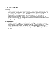
... supported high resolution color LCD monitor, Monitor can support multi-media function as Composite signal and S-Video signal input. 1.2 Description The LCD monitor is also a space saving design, allowing more desktop space, and comparing to general 15 pin D-sub VGA connector and DVI-D digital connector, eliminates the requirement of speakers. This will alleviate the growing health concerns. It is designed with the latest LCD technology to provide a performance oriented product with volume control...
... supported high resolution color LCD monitor, Monitor can support multi-media function as Composite signal and S-Video signal input. 1.2 Description The LCD monitor is also a space saving design, allowing more desktop space, and comparing to general 15 pin D-sub VGA connector and DVI-D digital connector, eliminates the requirement of speakers. This will alleviate the growing health concerns. It is designed with the latest LCD technology to provide a performance oriented product with volume control...
AL1731 Service Guide
Page 5
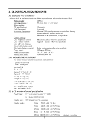
.../70/75 Hz) SXGA 1280 X 1024 (60/70/75 Hz) standard resolution 4 2. ELECTRICAL REQUIREMENTS 2.1 Standard Test Conditions All tests shall be performed under test. Ambient light: Viewing distance : Warrn up time All specifications: Fully functional: Measuring Equipment: Control settings User brightness control: User contrast control: User red/white balance, Green/white balance and Blue/white balance control: Power input : Ambient temperature : Analog input mode : 225 lux 50 cm in front of measure stated in this...
.../70/75 Hz) SXGA 1280 X 1024 (60/70/75 Hz) standard resolution 4 2. ELECTRICAL REQUIREMENTS 2.1 Standard Test Conditions All tests shall be performed under test. Ambient light: Viewing distance : Warrn up time All specifications: Fully functional: Measuring Equipment: Control settings User brightness control: User contrast control: User red/white balance, Green/white balance and Blue/white balance control: Power input : Ambient temperature : Analog input mode : 225 lux 50 cm in front of measure stated in this...
AL1731 Service Guide
Page 6
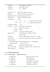
... Signal connector : 15 pin Mini D type, (standard VGA video) DVI-D connector Audio power : 1Wrms + 1Wrms ( 300Hz - 10kHz (S.P.L. - 10 dB)) Front control : power on/off with LED select (up, down) adjustment (+,-) Interface frequency Horizontal Frequency 30KHz --80KHz(analog), 31.5- 64KHz(digital) Vertical Frequency 56Hz ----75Hz Plug & play : Support VESA DDC2B functions Power Input voltage : Single phase, 50/60HZ, 100VAC to peak Sync : TTL positive or negative 2). Pixel pitch : Display Dot : Pixel Clock : 0.098x3mm(H) x 0.294mm(V) 1280 x (RGB) x 1024 25.2 - 135.0MHz Contrast...
... Signal connector : 15 pin Mini D type, (standard VGA video) DVI-D connector Audio power : 1Wrms + 1Wrms ( 300Hz - 10kHz (S.P.L. - 10 dB)) Front control : power on/off with LED select (up, down) adjustment (+,-) Interface frequency Horizontal Frequency 30KHz --80KHz(analog), 31.5- 64KHz(digital) Vertical Frequency 56Hz ----75Hz Plug & play : Support VESA DDC2B functions Power Input voltage : Single phase, 50/60HZ, 100VAC to peak Sync : TTL positive or negative 2). Pixel pitch : Display Dot : Pixel Clock : 0.098x3mm(H) x 0.294mm(V) 1280 x (RGB) x 1024 25.2 - 135.0MHz Contrast...
AL1731 Service Guide
Page 12
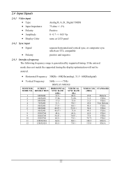
....0 40.0 50.0 49.5 65.0 75.0 78.75 108.5 135.0 Defacto VESA VESA Text Defacto VESA VESA VESA VESA VESA VESA SXGA SXGA 11 2.4 Input Signals 2.4.1 Video input • Type • Input Impedance • Polarity • Amplitude • Display Color Analog R, G, B., Digital TMDS 75 ohm +/- 2% Positive 0 - 0.7 +/- 0.05 Vp same as LCD panel 2.4.2 Sync input • Signal • Polarity separate horizontal and vertical sync, or composite sync which are TTL compatible positive and negative. 2.4.3 Interface frequency The following frequency range is generalized by supported timing.
....0 40.0 50.0 49.5 65.0 75.0 78.75 108.5 135.0 Defacto VESA VESA Text Defacto VESA VESA VESA VESA VESA VESA SXGA SXGA 11 2.4 Input Signals 2.4.1 Video input • Type • Input Impedance • Polarity • Amplitude • Display Color Analog R, G, B., Digital TMDS 75 ohm +/- 2% Positive 0 - 0.7 +/- 0.05 Vp same as LCD panel 2.4.2 Sync input • Signal • Polarity separate horizontal and vertical sync, or composite sync which are TTL compatible positive and negative. 2.4.3 Interface frequency The following frequency range is generalized by supported timing.

AL1731 Service Guide
Page 13
... 75 78.75 108 135 If the input timing is not a supported timing listed above mode and other video modes within the supported frequency range (Horizontal: 80KHz,Vertical: 75Hz), this monitor will be optimized. If the input timing over the supported frequency range, a message "Input Signal Out of Range" will be shown. 2.4.4 Support Modes There will select a closest mode instead. Digital TMDS MAX supports range 1280x1024 60Hz. 12 VGA-480 59.94 - 640x480 37.861 - XGA...
... 75 78.75 108 135 If the input timing is not a supported timing listed above mode and other video modes within the supported frequency range (Horizontal: 80KHz,Vertical: 75Hz), this monitor will be optimized. If the input timing over the supported frequency range, a message "Input Signal Out of Range" will be shown. 2.4.4 Support Modes There will select a closest mode instead. Digital TMDS MAX supports range 1280x1024 60Hz. 12 VGA-480 59.94 - 640x480 37.861 - XGA...
AL1731 Service Guide
Page 14
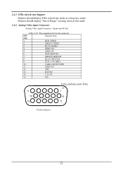
...85Hz refresh rate Support Monitor should display "Out of plastic parts: Blue 5 1 10 6 15 11 D-sub connector 13 Pin assignment for D-sub connector PIN Separate Sync NO. 1 RED VIDEO 2 GREEN VIDEO 3 BLUE VIDEO 4 GROUND 5 GROUND 6 RED GROUND 7 GREEN GROUND 8 BLUE GROUND 9 PC5V (+5V DDC) 10 CABLE DETECTION 11 GROUND 12 SDA 13 H.SYNC 14 V.SYNC 15 SCL Color of Range" warning menu at this mode. 2.4.6 Analog Video input Connector Analog Video input Connector: 15pins mini D-Sub Table 2.4.5. Monitor should display 85Hz refresh rate mode as emergency mode...
...85Hz refresh rate Support Monitor should display "Out of plastic parts: Blue 5 1 10 6 15 11 D-sub connector 13 Pin assignment for D-sub connector PIN Separate Sync NO. 1 RED VIDEO 2 GREEN VIDEO 3 BLUE VIDEO 4 GROUND 5 GROUND 6 RED GROUND 7 GREEN GROUND 8 BLUE GROUND 9 PC5V (+5V DDC) 10 CABLE DETECTION 11 GROUND 12 SDA 13 H.SYNC 14 V.SYNC 15 SCL Color of Range" warning menu at this mode. 2.4.6 Analog Video input Connector Analog Video input Connector: 15pins mini D-Sub Table 2.4.5. Monitor should display 85Hz refresh rate mode as emergency mode...
AL1731 Service Guide
Page 15
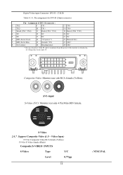
... is switched off and the power of the monitor is switched on, no voltage may occur at pin 14. Composite Video: Monitor rear side RCA female (Yellow). Pin assignment for S-Video female (Black) Composite/S-VIDEO INPUTS S-Video Type Y/C Level 0.7Vpp 14 : NTSC/PAL Video Input: JV3 for Composite Video RCA female (Yellow) JV4 for DVI-D (24pin) connector Pin - AV1-input S-Video (Y/C): Monitor rear side 4 Pin Mini-DIN female. S-Video 2.4.7 Support Composite Video & S - Digital Video input Connector: DVI...
... is switched off and the power of the monitor is switched on, no voltage may occur at pin 14. Composite Video: Monitor rear side RCA female (Yellow). Pin assignment for S-Video female (Black) Composite/S-VIDEO INPUTS S-Video Type Y/C Level 0.7Vpp 14 : NTSC/PAL Video Input: JV3 for Composite Video RCA female (Yellow) JV4 for DVI-D (24pin) connector Pin - AV1-input S-Video (Y/C): Monitor rear side 4 Pin Mini-DIN female. S-Video 2.4.7 Support Composite Video & S - Digital Video input Connector: DVI...
AL1731 Service Guide
Page 16
... press Menu buttons again for OSD first menu (left button to decrease the OSD setting and press the right button to switch the monitor ON/OFF. 2. LED lights Yellow --- Power is ON. 3. Press the Auto Buttons over 2 second the Monitor Searching next source. 1. You can adjusting speaker Volume control. 2. Press the Auto Buttons Monitor will enable selection function. 15 Monitor is off --- When OSD (On Screen Display) Menus display press Menu Buttons will Auto-Adjusting. 2. LED lights Blue color --- LED is in "Power Saving Mode". 4. When press after Menu buttons...
... press Menu buttons again for OSD first menu (left button to decrease the OSD setting and press the right button to switch the monitor ON/OFF. 2. LED lights Yellow --- Power is ON. 3. Press the Auto Buttons over 2 second the Monitor Searching next source. 1. You can adjusting speaker Volume control. 2. Press the Auto Buttons Monitor will enable selection function. 15 Monitor is off --- When OSD (On Screen Display) Menus display press Menu Buttons will Auto-Adjusting. 2. LED lights Blue color --- LED is in "Power Saving Mode". 4. When press after Menu buttons...

AL1731 Service Guide
Page 17
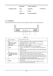
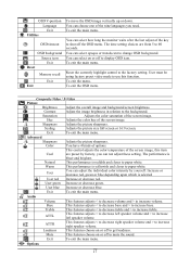
...selected User red Increase or decrease red. User green Increase or decrease green. 2.5.1 Adjusting the Monitor's Display The monitor has four function control buttons to increase base. OSD Function Menu To access OSD Main menu, simply press one of selected item. 2.5.2 Function Description Figure 2-2 2.5.2.1.1.1 Analog RGB / Digital RGB Picture Auto adjust Press > button, auto adjust the display mode to its utmost performance according to increase left speaker volume and > to VGA setting. Brightness Adjust the overall image and background screen brightness. Phase...
...selected User red Increase or decrease red. User green Increase or decrease green. 2.5.1 Adjusting the Monitor's Display The monitor has four function control buttons to increase base. OSD Function Menu To access OSD Main menu, simply press one of selected item. 2.5.2 Function Description Figure 2-2 2.5.2.1.1.1 Analog RGB / Digital RGB Picture Auto adjust Press > button, auto adjust the display mode to its utmost performance according to increase left speaker volume and > to VGA setting. Brightness Adjust the overall image and background screen brightness. Phase...
AL1731 Service Guide
Page 18
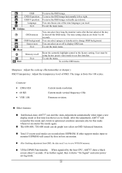
OSD V-position Language Exit Utilities OSD timeout OSD background Source icon Exit Reset Memory recall Exit Exit To move the OSD image vertically up or down. To exit the menu. Contrast Adjust the image brightness in relation to increase volume. Scaling Adjusts the picture size full screen or 16:9 screen. Advanced Sharpness Color Cool Natural Warm User User red User green User blue Adjusts the picture sharpness. This performance is selected Increase or decrease red. Increase or decrease red, green or blue depending upon which is...
OSD V-position Language Exit Utilities OSD timeout OSD background Source icon Exit Reset Memory recall Exit Exit To move the OSD image vertically up or down. To exit the menu. Contrast Adjust the image brightness in relation to increase volume. Scaling Adjusts the picture size full screen or 16:9 screen. Advanced Sharpness Color Cool Natural Warm User User red User green User blue Adjusts the picture sharpness. This performance is selected Increase or decrease red. Increase or decrease red, green or blue depending upon which is...
AL1731 Service Guide
Page 19
... 13 recent used modes are from 5 to use this mode again. If other support modes input to change OSD background. If no further signal, then it shows "No Signal" and enter power saving mode. 18 You can select how long the monitor waits after the last adjust of the nine languages you need 3 sec to optimized condition automatically for this mode whenever encounter this function. User must be using factory preset video mode to 60...
... 13 recent used modes are from 5 to use this mode again. If other support modes input to change OSD background. If no further signal, then it shows "No Signal" and enter power saving mode. 18 You can select how long the monitor waits after the last adjust of the nine languages you need 3 sec to optimized condition automatically for this mode whenever encounter this function. User must be using factory preset video mode to 60...
AL1731 Service Guide
Page 21
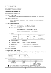
..., LSE0218B1260 IVO 90D) 2.7.1 input Voltage Range The monitor shall operate within specification over the range of 90 to 265 VAC power supply. 2.7.2 Input Frequency Range Input power frequency range shall be from 47.5 to 63 Hz over the specified input voltage range. 2.7.3 Quick specification review • Input current 1.2A (max) at 90VAC input and full load , 0.6A (max) at 264 VAC input and full load. • Inrush current @ cold start 30A(0-peak)@ 110Vac...
..., LSE0218B1260 IVO 90D) 2.7.1 input Voltage Range The monitor shall operate within specification over the range of 90 to 265 VAC power supply. 2.7.2 Input Frequency Range Input power frequency range shall be from 47.5 to 63 Hz over the specified input voltage range. 2.7.3 Quick specification review • Input current 1.2A (max) at 90VAC input and full load , 0.6A (max) at 264 VAC input and full load. • Inrush current @ cold start 30A(0-peak)@ 110Vac...

AL1731 Service Guide
Page 22
... Description +5Vdc for Audio ckt Ground for Open 12 Lamp Protection Topen /each lamp 13 Audible Noise Condition Min 11.4 Vin=12V,ILAMP= 7.5mA - Vopen 10 - Typ. 12 700 250 6.5 0 - - 60 1000 - Max. Item 1 Input Voltage 2 Lamp Voltage Sym Vin VLamp 3 Luminance Bmax 4 Working Frequency Fo 5 Lamp Current ILAMP Backlight ON/OFF ON 6 Control OFF 7 Brightness control range(positive adjustment) 8 Lamp Current...
... Description +5Vdc for Audio ckt Ground for Open 12 Lamp Protection Topen /each lamp 13 Audible Noise Condition Min 11.4 Vin=12V,ILAMP= 7.5mA - Vopen 10 - Typ. 12 700 250 6.5 0 - - 60 1000 - Max. Item 1 Input Voltage 2 Lamp Voltage Sym Vin VLamp 3 Luminance Bmax 4 Working Frequency Fo 5 Lamp Current ILAMP Backlight ON/OFF ON 6 Control OFF 7 Brightness control range(positive adjustment) 8 Lamp Current...
AL1731 Service Guide
Page 25
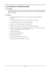
... convert the analog RGB signals from standard VGA display card to optimum LCD timing signals so as to construct a high display quality LCD monitor. 3.2 Features • On board embedded micro-processor to detect display timings and control user functions. • Using PixelWorks PW131 design to generate optimum LCD timings. 2 • Using E PROM to memorize every adjusted parameter. • Support up to 13 display modes from VGA to SXGA. • Offer full screen expansion function...
... convert the analog RGB signals from standard VGA display card to optimum LCD timing signals so as to construct a high display quality LCD monitor. 3.2 Features • On board embedded micro-processor to detect display timings and control user functions. • Using PixelWorks PW131 design to generate optimum LCD timings. 2 • Using E PROM to memorize every adjusted parameter. • Support up to 13 display modes from VGA to SXGA. • Offer full screen expansion function...
AL1731 Service Guide
Page 30
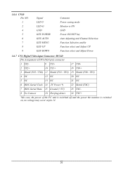
... 4 5 6 7 8 9 Signal LED-Y LED-G GND KEY-POWER KEY-AUTO KEY-MENU KEY-UP KEY-DOWN Comment Power saving mode Monitor is ON GND Power ON/OFF key Auto Adjusting and Channel Selection Function Selection enable Function select and Adjust UP Function select and Adjust Down 3.6.7 CN1 Digital Video input Connector: DVI-D Pin-Assignment of DVI-D(24 pin) connector 1 TX2- 9 TX1- 17 ...Serial Clock 14 -5V Power *) 22 Shield (TXC) 7 DDC-Serial Data 15 Ground (+5V) 23 TXC- 8 No Connect 16 Hot plug detect 24 TXC+ *)In case, the power of the PC unit is switched off and the power the monitor is switched...
... 4 5 6 7 8 9 Signal LED-Y LED-G GND KEY-POWER KEY-AUTO KEY-MENU KEY-UP KEY-DOWN Comment Power saving mode Monitor is ON GND Power ON/OFF key Auto Adjusting and Channel Selection Function Selection enable Function select and Adjust UP Function select and Adjust Down 3.6.7 CN1 Digital Video input Connector: DVI-D Pin-Assignment of DVI-D(24 pin) connector 1 TX2- 9 TX1- 17 ...Serial Clock 14 -5V Power *) 22 Shield (TXC) 7 DDC-Serial Data 15 Ground (+5V) 23 TXC- 8 No Connect 16 Hot plug detect 24 TXC+ *)In case, the power of the PC unit is switched off and the power the monitor is switched...
AL1731 Service Guide
Page 31
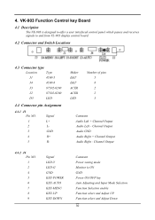
... select and Adjust Down 30 4. Maker E&T E&T ACER ACER LED Number of pins 5 8 2 2 3 Comment Audio Left + Channel Output Audio Left - Channel Output Audio GND Audio Right + Channel Output Audio Right - Channel Output 4.4.2 J4 Pin NO. 1 2 4 5 6 7 8 9 Signal LED-Y LED-G GND KEY-POWER KEY-AUTO KEY-MENU KEY-UP KEY-DOWN Comment Power saving mode Monitor is designed to offer a user interfaced control panel which passes and receives signals to and from VL-903 display control board. 4.2 Connector and Switch Locations 4.3 Connector type...
... select and Adjust Down 30 4. Maker E&T E&T ACER ACER LED Number of pins 5 8 2 2 3 Comment Audio Left + Channel Output Audio Left - Channel Output Audio GND Audio Right + Channel Output Audio Right - Channel Output 4.4.2 J4 Pin NO. 1 2 4 5 6 7 8 9 Signal LED-Y LED-G GND KEY-POWER KEY-AUTO KEY-MENU KEY-UP KEY-DOWN Comment Power saving mode Monitor is designed to offer a user interfaced control panel which passes and receives signals to and from VL-903 display control board. 4.2 Connector and Switch Locations 4.3 Connector type...
AL1731 User Guide
Page 1
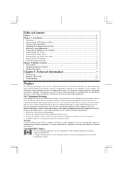
... an outlet on a circuit different from Its Stand 3 Interface for Arm Applications...3 Connecting the Display to your Computer 3 Connecting the AC Power...3 Connecting the Audio Cable ...3 Connecting the AV and S-Video cable 3 Setting Up the LCD Monitor...4 Power Management System ...4 Chapter 2 Display Controls 4 User Controls ...4 Adjusting the Monitor's Display...5 Function Description ...5 Chapter 3 Technical Information 7 Specifications ...7 Standard Timing Table...10 Troubleshooting ...10 Preface This manual is designed to assist users in accordance with the limits for compliance...
... an outlet on a circuit different from Its Stand 3 Interface for Arm Applications...3 Connecting the Display to your Computer 3 Connecting the AC Power...3 Connecting the Audio Cable ...3 Connecting the AV and S-Video cable 3 Setting Up the LCD Monitor...4 Power Management System ...4 Chapter 2 Display Controls 4 User Controls ...4 Adjusting the Monitor's Display...5 Function Description ...5 Chapter 3 Technical Information 7 Specifications ...7 Standard Timing Table...10 Troubleshooting ...10 Preface This manual is designed to assist users in accordance with the limits for compliance...

AL1731 User Guide
Page 2
... -4° ~ 140°F). Make sure that the Monitor does not become too hot. Then connect the LCD Monitor and base and screw it for sufficient airflow. Do not apply pressure to the display. 4. Store LCD Monitor in the box: * LCD Monitor * User's Manual * 1.8M Monitor-to-PC VGA Cable * AC Adapter * 1.8M Monitor-to-PC DVI-D Cable * 1.8M Power Cord * 1.8M Stereo Jack Audio Cable * 1.8M S-Video Cable * 1.8M RCA Jack Audio Video Cable If you open the box to +20...
... -4° ~ 140°F). Make sure that the Monitor does not become too hot. Then connect the LCD Monitor and base and screw it for sufficient airflow. Do not apply pressure to the display. 4. Store LCD Monitor in the box: * LCD Monitor * User's Manual * 1.8M Monitor-to-PC VGA Cable * AC Adapter * 1.8M Monitor-to-PC DVI-D Cable * 1.8M Power Cord * 1.8M Stereo Jack Audio Cable * 1.8M S-Video Cable * 1.8M RCA Jack Audio Video Cable If you open the box to +20...

AL1731 User Guide
Page 3
... AC adapter.(See Fig. 1-6) 2. These specifications meet the VESA Flat Panel Monitor Physical Mounting Interface Standard (paragraphs 2.1 and 2.1.3, version 1, dated 13 November 1997). Connect the other end of the signal cable to the LCD Monitor's VGA port or DVI port.(See Fig 1-5) 3. Connect the power cord to prevent the errects of the monitor. 3. Connecting the Audio Cable 1. Connect the other end of the signal cable to the VGA port or DVI port on your PC's audio card or to the front panel's "AUDIO OUT...
... AC adapter.(See Fig. 1-6) 2. These specifications meet the VESA Flat Panel Monitor Physical Mounting Interface Standard (paragraphs 2.1 and 2.1.3, version 1, dated 13 November 1997). Connect the other end of the signal cable to the LCD Monitor's VGA port or DVI port.(See Fig 1-5) 3. Connect the power cord to prevent the errects of the monitor. 3. Connecting the Audio Cable 1. Connect the other end of the signal cable to the VGA port or DVI port on your PC's audio card or to the front panel's "AUDIO OUT...


