AL1712 Service Guide
Page 8
Table of contents Chapter 1 Monitor Feature 9 Preset Timing 9 Block Diagram 9 PCB Conductor View 9 MainBoard 9 Button Board 9 Chapter 2 Operating Instruction 15 Front Panel Definition 9 External Controls 9 OSD Menu 9 LCD Definition 9 How to Optimize the DOS-Mode 9 Chapter 3 Machine Disassembly and Replacement 21 Dimension 9 Disassembly Procedures 9 Chapter 4 Troubleshooting 27 Chapter 5 Connector Information 29 Chapter 6 FRU List 30 Chapter 7 Schematic Diagram 34 - 8 -
Table of contents Chapter 1 Monitor Feature 9 Preset Timing 9 Block Diagram 9 PCB Conductor View 9 MainBoard 9 Button Board 9 Chapter 2 Operating Instruction 15 Front Panel Definition 9 External Controls 9 OSD Menu 9 LCD Definition 9 How to Optimize the DOS-Mode 9 Chapter 3 Machine Disassembly and Replacement 21 Dimension 9 Disassembly Procedures 9 Chapter 4 Troubleshooting 27 Chapter 5 Connector Information 29 Chapter 6 FRU List 30 Chapter 7 Schematic Diagram 34 - 8 -

AL1712 Service Guide
Page 21
Chapter 3 Machine Disassembly and Replacement This chapter contains step-by-step procedures on a soft surface when mounting or removing the base. 3. Wear gloves. During the disassembly process, group the screws with the corresponding to assemble the monitor for the different components vary in size. The screws for maintenance and trouble shooting NOTE : 1. Therefore, lay the monitor on how to avoid mismatch when putting back the components. 2. Note : The monitor surface is susceptible to scratching! DIMENSION Front View : ( unit : mm ) - 21 -
Chapter 3 Machine Disassembly and Replacement This chapter contains step-by-step procedures on a soft surface when mounting or removing the base. 3. Wear gloves. During the disassembly process, group the screws with the corresponding to assemble the monitor for the different components vary in size. The screws for maintenance and trouble shooting NOTE : 1. Therefore, lay the monitor on how to avoid mismatch when putting back the components. 2. Note : The monitor surface is susceptible to scratching! DIMENSION Front View : ( unit : mm ) - 21 -
AL1712 Service Guide
Page 24
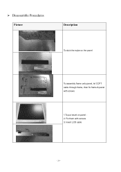
Disassemble Procedures Picture Description To stick the mylar on the panel To assembly frame onto panel, let CCFT cable through frame, then fix frame & panel with screws. 3. Insert LCD cable - 24 - Fix them with screws 1.To put bezel on panel : 2.
Disassemble Procedures Picture Description To stick the mylar on the panel To assembly frame onto panel, let CCFT cable through frame, then fix frame & panel with screws. 3. Insert LCD cable - 24 - Fix them with screws 1.To put bezel on panel : 2.


