

AL1712 Service Guide
Page 2
...; 2003 by any particular purpose, Any Acer Incorporated software described in this manual is sold or licensed "as is ". All rights reserved. Acer Incorporated makes no representations or warranties, either expresses or implied, with respect to change without the prior written permission of this guide is a registered trademark of all necessary servicing, repair, and any incidental or consequential damages...
...; 2003 by any particular purpose, Any Acer Incorporated software described in this manual is sold or licensed "as is ". All rights reserved. Acer Incorporated makes no representations or warranties, either expresses or implied, with respect to change without the prior written permission of this guide is a registered trademark of all necessary servicing, repair, and any incidental or consequential damages...

AL1712 Service Guide
Page 4
..., for whatever reason, a part number change is made, it supports, please read the following general information. 1. add-on your regional office MAY have a DIFFERENT part number code to those given in this generic service guide. please not WHEN ORDERING FRU PARTS, that you with all technical information relating to the BASICCONFIGURATION decided for repair and Service of this printed Service Guide. In such cases...
..., for whatever reason, a part number change is made, it supports, please read the following general information. 1. add-on your regional office MAY have a DIFFERENT part number code to those given in this generic service guide. please not WHEN ORDERING FRU PARTS, that you with all technical information relating to the BASICCONFIGURATION decided for repair and Service of this printed Service Guide. In such cases...
AL1712 Service Guide
Page 5
... frequency energy, and if not installed and used in accordance with the instructions, may cause harmful interference to radio communications. Consult the dealer or an experienced radio/TV technician for help. WARNING: To prevent fire or chock hazard, do not expose the monitor to qualified personnel only. - 5 - Increase the separation between the equipment and receiver. 3. Refer servicing...
... frequency energy, and if not installed and used in accordance with the instructions, may cause harmful interference to radio communications. Consult the dealer or an experienced radio/TV technician for help. WARNING: To prevent fire or chock hazard, do not expose the monitor to qualified personnel only. - 5 - Increase the separation between the equipment and receiver. 3. Refer servicing...

AL1712 Service Guide
Page 6
... refer all servicing to service the monitor yourself; Do not place the monitor on the monitor cabinet. This plug will not be sure these openings are not sure of the type of the cabinet area provided for long periods of power source indicated on a wall or shelf, use the monitor only with the attached power adapter (output 12V DC) which have an electrician install the...
... refer all servicing to service the monitor yourself; Do not place the monitor on the monitor cabinet. This plug will not be sure these openings are not sure of the type of the cabinet area provided for long periods of power source indicated on a wall or shelf, use the monitor only with the attached power adapter (output 12V DC) which have an electrician install the...
AL1712 Service Guide
Page 7
... image is recovered slowly by changing the image or turning off the Power Switch and then turn it on the desktop pattern you use . In this case, the screen is displayed for hours. - 7 - Due to the nature of the LCD screen, an afterimage of the previous screen may find slightly uneven brightness in the screen depending on again to the nature of the fluorescent light, the screen...
... image is recovered slowly by changing the image or turning off the Power Switch and then turn it on the desktop pattern you use . In this case, the screen is displayed for hours. - 7 - Due to the nature of the LCD screen, an afterimage of the previous screen may find slightly uneven brightness in the screen depending on again to the nature of the fluorescent light, the screen...
AL1712 Service Guide
Page 8
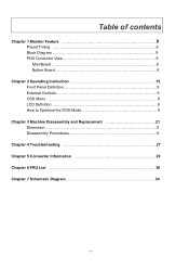
Table of contents Chapter 1 Monitor Feature 9 Preset Timing 9 Block Diagram 9 PCB Conductor View 9 MainBoard 9 Button Board 9 Chapter 2 Operating Instruction 15 Front Panel Definition 9 External Controls 9 OSD Menu 9 LCD Definition 9 How to Optimize the DOS-Mode 9 Chapter 3 Machine Disassembly and Replacement 21 Dimension 9 Disassembly Procedures 9 Chapter 4 Troubleshooting 27 Chapter 5 Connector Information 29 Chapter 6 FRU List 30 Chapter 7 Schematic Diagram 34 - 8 -
Table of contents Chapter 1 Monitor Feature 9 Preset Timing 9 Block Diagram 9 PCB Conductor View 9 MainBoard 9 Button Board 9 Chapter 2 Operating Instruction 15 Front Panel Definition 9 External Controls 9 OSD Menu 9 LCD Definition 9 How to Optimize the DOS-Mode 9 Chapter 3 Machine Disassembly and Replacement 21 Dimension 9 Disassembly Procedures 9 Chapter 4 Troubleshooting 27 Chapter 5 Connector Information 29 Chapter 6 FRU List 30 Chapter 7 Schematic Diagram 34 - 8 -
AL1712 Service Guide
Page 9
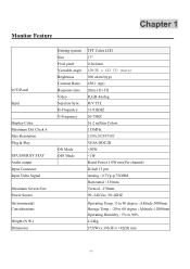
Monitor Feature Chapter 1 LCD Panel Input Display Color Maximum Dot Clock ® Max Resolution Plug & Play EPA ENERGY STAY Audio output Input Connector Input Video Signal Maximum Screen Size Power Source Environmental Considerations Weight (N.W.) Dimension Driving system Size Pixel pitch Viewable angle Brightness Contrast Ratio Response time Video Separate Sync H-Frequency V-Frequency ON Mode OFF Mode TFT Color LCD 17" 0.264 mm 150(H) x 125 (V) degree 300 cd/m2(typ) 450:1 (typ) 20ms (Tr+Tf) R,G,B Analog H/V TTL 31-81KHZ 56-75HZ 16.2 million Colors 135MHz 1280x1024@75HZ VESA DDC2B
Monitor Feature Chapter 1 LCD Panel Input Display Color Maximum Dot Clock ® Max Resolution Plug & Play EPA ENERGY STAY Audio output Input Connector Input Video Signal Maximum Screen Size Power Source Environmental Considerations Weight (N.W.) Dimension Driving system Size Pixel pitch Viewable angle Brightness Contrast Ratio Response time Video Separate Sync H-Frequency V-Frequency ON Mode OFF Mode TFT Color LCD 17" 0.264 mm 150(H) x 125 (V) degree 300 cd/m2(typ) 450:1 (typ) 20ms (Tr+Tf) R,G,B Analog H/V TTL 31-81KHZ 56-75HZ 16.2 million Colors 135MHz 1280x1024@75HZ VESA DDC2B
AL1712 Service Guide
Page 10
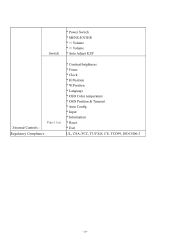
Switch * Power Switch * MENU/ENTER * >/ Volume *
Switch * Power Switch * MENU/ENTER * >/ Volume *
AL1712 Service Guide
Page 12
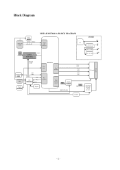
Panel Interface Host Interface Panel Inverter control Switch 5V Si2301DS BRIGHTNESS TX1+ TX1- Block Diagram ANALOG RGB DDC 24LC02 HSYNC ,VSYNC AR AG AB MSTAR MST8111A BLOCK DIAGRAM Triple 12V ADC Interface 12V VOLU AUDIO TDA7496L POWER 12V 5V AIC1563 3.3V AIC117ADJ 2.5V AIC1117ADJ Backlight EEPROM 24C16 ISP Crystal 14.318MHz MUTE STBY SCL SDA CPU MTV312V64 RST IRQ CSZ Keypad MST8111A Clock GEN. TX2+ TX2- TXC+ TXC- 17" Panel 12V ADAPTOR Backlight Control Inverter ON/OFF - 12 -
Panel Interface Host Interface Panel Inverter control Switch 5V Si2301DS BRIGHTNESS TX1+ TX1- Block Diagram ANALOG RGB DDC 24LC02 HSYNC ,VSYNC AR AG AB MSTAR MST8111A BLOCK DIAGRAM Triple 12V ADC Interface 12V VOLU AUDIO TDA7496L POWER 12V 5V AIC1563 3.3V AIC117ADJ 2.5V AIC1117ADJ Backlight EEPROM 24C16 ISP Crystal 14.318MHz MUTE STBY SCL SDA CPU MTV312V64 RST IRQ CSZ Keypad MST8111A Clock GEN. TX2+ TX2- TXC+ TXC- 17" Panel 12V ADAPTOR Backlight Control Inverter ON/OFF - 12 -

AL1712 Service Guide
Page 15
... adjust OSD options. If OSD is inactive, press once, then press the buttons marked < or > to adjust the volume. 3 > PLUS If OSD is active, press to exit a selection in sleep mode - 15 - If OSD is inactive, press 1. Power on/off 5 POWER Green: power on Orange: in OSD. Press to view OSD. 4 OSD Function Press again to adjust the volume. OPERATING INSTRUCTIONS Chapter 2 Front Panel Definition This Section defines the front panel User Interface for Led...
... adjust OSD options. If OSD is inactive, press once, then press the buttons marked < or > to adjust the volume. 3 > PLUS If OSD is active, press to exit a selection in sleep mode - 15 - If OSD is inactive, press 1. Power on/off 5 POWER Green: power on Orange: in OSD. Press to view OSD. 4 OSD Function Press again to adjust the volume. OPERATING INSTRUCTIONS Chapter 2 Front Panel Definition This Section defines the front panel User Interface for Led...
AL1712 Service Guide
Page 16
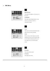
V-Position: This adjusts the vertical. - 16 - CONTRAST: This adjusts dark and light shades of the screen this renders them less noticeable by minimizing their size. Focus: This removes any vertical stripes seen on the screen. Clock: If there are any horizontal distortion and makes the picture clear and sharp. It also changes the size of the picture on the background of color relative to each other to achieve a comfortable contrast. H-Position: This adjusts the horizontal. OSD Menu BRIGHTNESS: This adjusts the brightness of the horizontal screen.
V-Position: This adjusts the vertical. - 16 - CONTRAST: This adjusts dark and light shades of the screen this renders them less noticeable by minimizing their size. Focus: This removes any vertical stripes seen on the screen. Clock: If there are any horizontal distortion and makes the picture clear and sharp. It also changes the size of the picture on the background of color relative to each other to achieve a comfortable contrast. H-Position: This adjusts the horizontal. OSD Menu BRIGHTNESS: This adjusts the brightness of the horizontal screen.

AL1712 Service Guide
Page 17
OSD SETTING: This changes the position of adjusting color: Warm (Reddish white) Cool (Bluish white) User defined: You can adjust the colors red, green and blue to the intensity you desire. LANGUAGE: Select the OSD menu language from English, German, and Spanish, Simple-Chinese, Traditional-Chinese, French, Italian, Japanese. There are three ways of the OSD window on the screen and staying time AUTO CONFIG System runs auto-configuration. - 17 -
OSD SETTING: This changes the position of adjusting color: Warm (Reddish white) Cool (Bluish white) User defined: You can adjust the colors red, green and blue to the intensity you desire. LANGUAGE: Select the OSD menu language from English, German, and Spanish, Simple-Chinese, Traditional-Chinese, French, Italian, Japanese. There are three ways of the OSD window on the screen and staying time AUTO CONFIG System runs auto-configuration. - 17 -
AL1712 Service Guide
Page 18
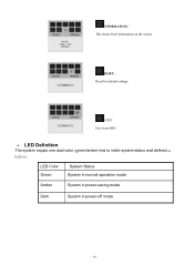
INFORMATION: This shows brief information on the screen. RESET: Recall to default settings EXIT Exit from OSD LED Definition The system equips one dual color (green/amber) led to indict system status and defined as bellows : LED Color Green System Status System in normal operation mode Amber System in power-saving mode Dark System in power-off mode - 18 -
INFORMATION: This shows brief information on the screen. RESET: Recall to default settings EXIT Exit from OSD LED Definition The system equips one dual color (green/amber) led to indict system status and defined as bellows : LED Color Green System Status System in normal operation mode Amber System in power-saving mode Dark System in power-off mode - 18 -

AL1712 Service Guide
Page 19
... MUST BE A VIDEO INPUT SIGNAL. This monitor meets the Green monitor standards as set by pressing a key on the I2C protocol. THIS MONITOR WILL APPEAR TO BE NON-FUNCTIONAL IF THERE IS NO VIDEO INPUT SIGNAL. When there is no video-input signal present. After the video input signal is restored, full power is restored and the display is completely off. The DDC2Bis a bidirectional data channel based on the keyboard...
... MUST BE A VIDEO INPUT SIGNAL. This monitor meets the Green monitor standards as set by pressing a key on the I2C protocol. THIS MONITOR WILL APPEAR TO BE NON-FUNCTIONAL IF THERE IS NO VIDEO INPUT SIGNAL. When there is no video-input signal present. After the video input signal is restored, full power is restored and the display is completely off. The DDC2Bis a bidirectional data channel based on the keyboard...

AL1712 Service Guide
Page 20
... a grounding type attachment plug, rated 10A, 250V,CEE-22 male configuration. Please note that power supply card needs to power outlet of personal computer: Please use VDE 0602, 0625, 0821 approval power cord in European counties. - 20 - One end terminates with a molded-on type connector body, rated 10A, 250V, having standard CEE-22 female configuration. USING THE RIGHT POWER CORD The accessory power cord for the Northern...
... a grounding type attachment plug, rated 10A, 250V,CEE-22 male configuration. Please note that power supply card needs to power outlet of personal computer: Please use VDE 0602, 0625, 0821 approval power cord in European counties. - 20 - One end terminates with a molded-on type connector body, rated 10A, 250V, having standard CEE-22 female configuration. USING THE RIGHT POWER CORD The accessory power cord for the Northern...

AL1712 Service Guide
Page 21
DIMENSION Front View : ( unit : mm ) - 21 - Wear gloves. During the disassembly process, group the screws with the corresponding to scratching! Therefore, lay the monitor on how to assemble the monitor for the different components vary in size. Note : The monitor surface is susceptible to avoid mismatch when putting back the components. 2. Chapter 3 Machine Disassembly and Replacement This chapter contains step-by-step procedures on a soft surface when mounting or removing the base. 3. The screws for maintenance and trouble shooting NOTE : 1.
DIMENSION Front View : ( unit : mm ) - 21 - Wear gloves. During the disassembly process, group the screws with the corresponding to scratching! Therefore, lay the monitor on how to assemble the monitor for the different components vary in size. Note : The monitor surface is susceptible to avoid mismatch when putting back the components. 2. Chapter 3 Machine Disassembly and Replacement This chapter contains step-by-step procedures on a soft surface when mounting or removing the base. 3. The screws for maintenance and trouble shooting NOTE : 1.
AL1712 Service Guide
Page 24
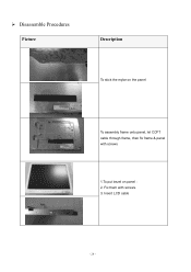
Disassemble Procedures Picture Description To stick the mylar on panel : 2. Fix them with screws 1.To put bezel on the panel To assembly frame onto panel, let CCFT cable through frame, then fix frame & panel with screws. 3. Insert LCD cable - 24 -
Disassemble Procedures Picture Description To stick the mylar on panel : 2. Fix them with screws 1.To put bezel on the panel To assembly frame onto panel, let CCFT cable through frame, then fix frame & panel with screws. 3. Insert LCD cable - 24 -
AL1712 Service Guide
Page 27
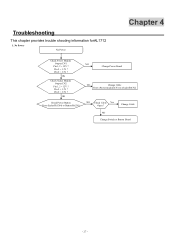
OK Check Scalar Module Output CN2 Pin 1,2 = 12V ? Change Cable NO Change Switch or Button Board - 27 - OK Check Power Button From Scalar/B(CN4) to Button/B(CN1) NO Change Power Board NO Change Cable From (Power module)CN1 to (Scalar/B)CN2 NO Check Cable Yes Open ? Pin 6 = 3.3V ? Pin 5 = 3.3V ? Troubleshooting This chapter provides trouble shooting information forAL1712 1. No Power No Power Chapter 4 Check Power Module Output CN1 Pin 1,2 = 12V ? Pin 5 = 3.3V ? Pin 6 = 3.3V ?
OK Check Scalar Module Output CN2 Pin 1,2 = 12V ? Change Cable NO Change Switch or Button Board - 27 - OK Check Power Button From Scalar/B(CN4) to Button/B(CN1) NO Change Power Board NO Change Cable From (Power module)CN1 to (Scalar/B)CN2 NO Check Cable Yes Open ? Pin 6 = 3.3V ? Pin 5 = 3.3V ? Troubleshooting This chapter provides trouble shooting information forAL1712 1. No Power No Power Chapter 4 Check Power Module Output CN1 Pin 1,2 = 12V ? Pin 5 = 3.3V ? Pin 6 = 3.3V ?

AL1712 Service Guide
Page 30
... or regulations on how best to dispose it, or follow the rules set by your regional Acer office on your Acer office may have a DIFFERENT part number code to those given in the printed Service Guide. You MUST use the local FRU list provided by your regional Acer office to order FRU parts repair and service of AL1712. For whatever reasons a part number change is made, it . - 30...
... or regulations on how best to dispose it, or follow the rules set by your regional Acer office on your Acer office may have a DIFFERENT part number code to those given in the printed Service Guide. You MUST use the local FRU list provided by your regional Acer office to order FRU parts repair and service of AL1712. For whatever reasons a part number change is made, it . - 30...
AL1712 Service Guide
Page 34
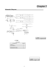
...C54 0.047u R40 100/6 C53 0.047u R42 100/6 C55 0.01U/6 R39 100/6 C52 0.047u R38 100/6 C51 0.047u RED+ 4 RED- 4 GREEN+ 4 GREEN- 4 SOGIN 4 BLUE+ 4 BLUE- 4 IN-H L22 0/6 R32 HSYNC 1K/6 1% HSYNC 4 R36 2K/6 C64 33P/6 IN-V R57 22/6 GND R31 ...NS D13 D7 2 L7T M/B CONTENTS SCHEMATIC CONTENT BLOCK DIAGRAM VGA AND TMDS INPUT MICRO AND BOTTON CONTROL POWER ADN OUTPUT CONNECT SHEET 1 2 3 4 5 6 Title Size Date: CONTENT Document Number SCHEMATIC1 11, 2003 Rev VGA AND TMDS INPUT 2A Sheet 3 of 7 Title Size Date: CONTENT Document Number SCHEMATIC1 11, 2003 CONTENT Sheet 1...
...C54 0.047u R40 100/6 C53 0.047u R42 100/6 C55 0.01U/6 R39 100/6 C52 0.047u R38 100/6 C51 0.047u RED+ 4 RED- 4 GREEN+ 4 GREEN- 4 SOGIN 4 BLUE+ 4 BLUE- 4 IN-H L22 0/6 R32 HSYNC 1K/6 1% HSYNC 4 R36 2K/6 C64 33P/6 IN-V R57 22/6 GND R31 ...NS D13 D7 2 L7T M/B CONTENTS SCHEMATIC CONTENT BLOCK DIAGRAM VGA AND TMDS INPUT MICRO AND BOTTON CONTROL POWER ADN OUTPUT CONNECT SHEET 1 2 3 4 5 6 Title Size Date: CONTENT Document Number SCHEMATIC1 11, 2003 Rev VGA AND TMDS INPUT 2A Sheet 3 of 7 Title Size Date: CONTENT Document Number SCHEMATIC1 11, 2003 CONTENT Sheet 1...

