

al1711ug.pdf
Page 1
. TABLE OF CONTENTS FOR YOUR SAFETY 1 SAFETY PRECAUTIONS 2 SPECIAL NOTES ON LCD MONITORS 3 BEFORE YOU OPERATE THE MONITOR 3 FEATURES 3 PACKING LIST 3 INSTALLATION INSTRUCTIONS 4 CONTROLS AND CONNECTORS 5 ADJUSTING THE VIEWING ANGLE 6 OPERATING INSTRUCTIONS 7 GENERAL INSTRUCTIONS 7 HOW TO ADJUST A SETTING 9 ADJUSTING THE PICTURE 9-10 PLUG AND PLAY 11 TECHNICAL SUPPORT(FAQ 12-13 ERROR MESSAGE & POSSIBLE SOLUTION ------- 14 APPENDIX 15 SPECIFICATIONS 15-16 FACTORY PRESET TIMING TABLE 17 CONNECTOR PIN ASSIGNMENT 17
. TABLE OF CONTENTS FOR YOUR SAFETY 1 SAFETY PRECAUTIONS 2 SPECIAL NOTES ON LCD MONITORS 3 BEFORE YOU OPERATE THE MONITOR 3 FEATURES 3 PACKING LIST 3 INSTALLATION INSTRUCTIONS 4 CONTROLS AND CONNECTORS 5 ADJUSTING THE VIEWING ANGLE 6 OPERATING INSTRUCTIONS 7 GENERAL INSTRUCTIONS 7 HOW TO ADJUST A SETTING 9 ADJUSTING THE PICTURE 9-10 PLUG AND PLAY 11 TECHNICAL SUPPORT(FAQ 12-13 ERROR MESSAGE & POSSIBLE SOLUTION ------- 14 APPENDIX 15 SPECIFICATIONS 15-16 FACTORY PRESET TIMING TABLE 17 CONNECTOR PIN ASSIGNMENT 17

al1711ug.pdf
Page 2
...B digital device, pursuant to Part 15 of the following measures: 1. WARNING: To prevent fire or shock hazard, do not expose the monitor to radio communications. This equipment generates, uses and can be used in a residential installation. Shielded interface cables and AC power cord, if... protection against harmful interference in accordance with the limits for help. Do not open the cabinet. These limits are present inside the monitor. FCC Class B Radio Frequency Interference Statement WARNING: (FOR FCC CERTIFIED MODELS) NOTE: This equipment has been tested and found to...
...B digital device, pursuant to Part 15 of the following measures: 1. WARNING: To prevent fire or shock hazard, do not expose the monitor to radio communications. This equipment generates, uses and can be used in a residential installation. Shielded interface cables and AC power cord, if... protection against harmful interference in accordance with the limits for help. Do not open the cabinet. These limits are present inside the monitor. FCC Class B Radio Frequency Interference Statement WARNING: (FOR FCC CERTIFIED MODELS) NOTE: This equipment has been tested and found to...
al1711ug.pdf
Page 3
... damage to protect it will fit only into the slot on an unstable cart, stand, or table. Do not place the monitor near water, e.g. z The monitor should be used for ventilation. z Unplug the unit during a lightening storm or when it from the type of power source ...radiator or heat register. To ensure reliable operation of the grounded plug. If you mount the monitor on the label. z The monitor is provided. Do not defeat the safety purpose of the monitor and to the appliance. Overloading can result in a bookcase or cabinet unless proper ventilation is ...
... damage to protect it will fit only into the slot on an unstable cart, stand, or table. Do not place the monitor near water, e.g. z The monitor should be used for ventilation. z Unplug the unit during a lightening storm or when it from the type of power source ...radiator or heat register. To ensure reliable operation of the grounded plug. If you mount the monitor on the label. z The monitor is provided. Do not defeat the safety purpose of the monitor and to the appliance. Overloading can result in a bookcase or cabinet unless proper ventilation is ...

al1711ug.pdf
Page 4
... depending on the desktop pattern you use . NOTES • Due to the nature of the LCD screen, an afterimage of 99.99% or more. LCD Monitor 2. Owner's Manual 3. Power Cord 4. 15-pin D-Sub Cable 5. In this case, the screen is displayed for Windows • Recommened Resolutions: 1280 X 1024 ... Saving, Compact Case Design CHECKING THE CONTENTS OF THE PACKAGE The product package should include the following symptoms are normal with LCD monitor and do not indicate a problem. SPECIAL NOTES ON LCD MONITORS The following items: 1. Turn off the Power Switch for Audio model) 3
... depending on the desktop pattern you use . NOTES • Due to the nature of the LCD screen, an afterimage of 99.99% or more. LCD Monitor 2. Owner's Manual 3. Power Cord 4. 15-pin D-Sub Cable 5. In this case, the screen is displayed for Windows • Recommened Resolutions: 1280 X 1024 ... Saving, Compact Case Design CHECKING THE CONTENTS OF THE PACKAGE The product package should include the following symptoms are normal with LCD monitor and do not indicate a problem. SPECIAL NOTES ON LCD MONITORS The following items: 1. Turn off the Power Switch for Audio model) 3
al1711ug.pdf
Page 5
... voltage area (No user adjustment is the correct type required in either a wall power outlet or the power outlet socket on your LCD monitor. The AC-power cord may be used with your PC, depending on the type of synthetic rubber according to IEC 60227 (designation H05VV...-F 3G 0.75mm2 or H05VVH2-F2 3G 0.75mm2) shall be considered. Make sure that allows operation in your LCD monitor's DC-power-input. A certified power supply cord not lighter than ordinary polyvinyl chloride flexible cord according to IEC 60245 (designation H05RR-F 3G 0.75mm2...
... voltage area (No user adjustment is the correct type required in either a wall power outlet or the power outlet socket on your LCD monitor. The AC-power cord may be used with your PC, depending on the type of synthetic rubber according to IEC 60227 (designation H05VV...-F 3G 0.75mm2 or H05VVH2-F2 3G 0.75mm2) shall be considered. Make sure that allows operation in your LCD monitor's DC-power-input. A certified power supply cord not lighter than ordinary polyvinyl chloride flexible cord according to IEC 60245 (designation H05RR-F 3G 0.75mm2...
al1711ug.pdf
Page 6
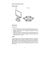
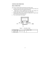
.... 1 Connect one end of the power cord into a nearby outlet. Power Cable 2. 3. Audio cable (Option-only for Audio model)Connect the audio cable between the monitor's audio input and the PC's audio output (green port). 5. CONTROLS AND CONNECTORS CABLE CONNECTIONS Turn off your... monitor into the PC port. 6. Plug the other end to the back of the monitor and connect the other end of the 15-pin VGA cable to the computer's D-Sub port. 4. (Option-only for Audio model...
.... 1 Connect one end of the power cord into a nearby outlet. Power Cable 2. 3. Audio cable (Option-only for Audio model)Connect the audio cable between the monitor's audio input and the PC's audio output (green port). 5. CONTROLS AND CONNECTORS CABLE CONNECTIONS Turn off your... monitor into the PC port. 6. Plug the other end to the back of the monitor and connect the other end of the 15-pin VGA cable to the computer's D-Sub port. 4. (Option-only for Audio model...
al1711ug.pdf
Page 7
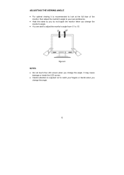
Figure 2 NOTES • Do not touch the LCD screen when you change the angle. ADJUSTING THE VIEWING ANGLE • For optimal viewing it is required not to catch your own preference. • Hold the stand so you do not topple the monitor when you change the monitor's angle. • You are able to adjust the monitor's angle from -5° to your fingers or hands when you change the angle. 6 It may cause damage or break the LCD screen. • Careful attention is recommended to look at the full face of the monitor, then adjust the monitor's angle to 15°.
Figure 2 NOTES • Do not touch the LCD screen when you change the angle. ADJUSTING THE VIEWING ANGLE • For optimal viewing it is required not to catch your own preference. • Hold the stand so you do not topple the monitor when you change the monitor's angle. • You are able to adjust the monitor's angle from -5° to your fingers or hands when you change the angle. 6 It may cause damage or break the LCD screen. • Careful attention is recommended to look at the full face of the monitor, then adjust the monitor's angle to 15°.

al1711ug.pdf
Page 8
The other control buttons are located at front panel of the monitor (See Figure 3). Auto Adjust Key/Exit 2. / Volume 4. Figure 3 External Control Button EXTERNAL CONTROLS 1. By changing these settings, the picture can be adjusted to your personal ...preferences. • The power cord should be connected. • Connect the video cable from the monitor to the video card. • Press the power button to turn on or off. The power indicator will light up. LED 6. /Power Key 7 MENU/ENTER...
The other control buttons are located at front panel of the monitor (See Figure 3). Auto Adjust Key/Exit 2. / Volume 4. Figure 3 External Control Button EXTERNAL CONTROLS 1. By changing these settings, the picture can be adjusted to your personal ...preferences. • The power cord should be connected. • Connect the video cable from the monitor to the video card. • Press the power button to turn on or off. The power indicator will light up. LED 6. /Power Key 7 MENU/ENTER...

al1711ug.pdf
Page 9
... mechanical vibration or shock. • Save the original shipping carton and packing materials, as it was originally packed at the factory. • To keep the monitor looking new, periodically clean it . 8 FRONT PANEL CONTROL • /Power Button: Press this button will act as EXIT-KEY (EXIT OSD menu). 2.... a location near heat sources such as radiators or air ducts, or in active status, this button to turn the monitor ON or OFF, And display the monitor's state. • Power Indicator: Green - When OSD menu is in off mode • MENU / ENTER : Activate OSD menu when OSD is ...
... mechanical vibration or shock. • Save the original shipping carton and packing materials, as it was originally packed at the factory. • To keep the monitor looking new, periodically clean it . 8 FRONT PANEL CONTROL • /Power Button: Press this button will act as EXIT-KEY (EXIT OSD menu). 2.... a location near heat sources such as radiators or air ducts, or in active status, this button to turn the monitor ON or OFF, And display the monitor's state. • Power Indicator: Green - When OSD menu is in off mode • MENU / ENTER : Activate OSD menu when OSD is ...
al1711ug.pdf
Page 12
... the host that power supply cord needs to use a cord set by reducing power consumption when there is no video input signal this monitor, following a time-out period, will automatically switch to conserve electrical energy by the Video Electronics Standards Association (VESA) and/or the... United States Environmental Protection Agency (EPA) and The Swedish Confederation Employees (NUTEK). IN ORDER FOR THIS MONITOR TO OPERATE PROPERLY, THERE MUST BE A VIDEO INPUT SIGNAL. This feature is designed to an OFF mode. The voltage rating for the ...
... the host that power supply cord needs to use a cord set by reducing power consumption when there is no video input signal this monitor, following a time-out period, will automatically switch to conserve electrical energy by the Video Electronics Standards Association (VESA) and/or the... United States Environmental Protection Agency (EPA) and The Swedish Confederation Employees (NUTEK). IN ORDER FOR THIS MONITOR TO OPERATE PROPERLY, THERE MUST BE A VIDEO INPUT SIGNAL. This feature is designed to an OFF mode. The voltage rating for the ...

al1711ug.pdf
Page 13
... key on No Plug & Play Picture is fuzzy Picture bounces or a wave pattern is present in its slot *Make sure monitor's video cable is properly connected to the computer. *Inspect monitor's video cable and make sure that none of the pins are bent. 12 The LED should be in the ON position.... *Computer Video Card should either turn ON or OFF after hitting the CAPS LOCK key. *Inspect the monitor's video cable and make sure none of the pins are bent. *Make sure computer is ON (orange) but there's no video or no picture. TECHNICAL...
... key on No Plug & Play Picture is fuzzy Picture bounces or a wave pattern is present in its slot *Make sure monitor's video cable is properly connected to the computer. *Inspect monitor's video cable and make sure that none of the pins are bent. 12 The LED should be in the ON position.... *Computer Video Card should either turn ON or OFF after hitting the CAPS LOCK key. *Inspect the monitor's video cable and make sure none of the pins are bent. *Make sure computer is ON (orange) but there's no video or no picture. TECHNICAL...

AL1711 Service Guide
Page 8
Table of Contents Chapter 1 Monitor Features 8 Monitor Features 8 Factory Preset Timing Table 10 Block Diagram 11 Mainboard Diagram 12 Software Flowchart 13 Mainboard Layout 15 Invertor Board Layout 17 Front Bezel View ...
Table of Contents Chapter 1 Monitor Features 8 Monitor Features 8 Factory Preset Timing Table 10 Block Diagram 11 Mainboard Diagram 12 Software Flowchart 13 Mainboard Layout 15 Invertor Board Layout 17 Front Bezel View ...

AL1711 Service Guide
Page 15
... power off status from first AC power up. Check if input timing has been changed, if yes then go to 10, else go to recover monitor settings, including brightness, contrast, color temperature and OSD position .... Initialize OSD menu variable for user operation 5. etc. 3. Debug handler, only debug only Initialize MCU settings...
... power off status from first AC power up. Check if input timing has been changed, if yes then go to 10, else go to recover monitor settings, including brightness, contrast, color temperature and OSD position .... Initialize OSD menu variable for user operation 5. etc. 3. Debug handler, only debug only Initialize MCU settings...

AL1711 Service Guide
Page 16
Monitor Board Layout
Monitor Board Layout
AL1711 Service Guide
Page 29
NOTE: 1.The screws for maintenance and troubleshooting. During the disassembly process, group the screws with the corresponding components to assemble the monitor for the different components vary in size. Machine Disassembly This chapter contains step-by-step procedures on how to avoid mismatch when putting back the components. 2. 3.
NOTE: 1.The screws for maintenance and troubleshooting. During the disassembly process, group the screws with the corresponding components to assemble the monitor for the different components vary in size. Machine Disassembly This chapter contains step-by-step procedures on how to avoid mismatch when putting back the components. 2. 3.

AL1711 Service Guide
Page 35
Connector Information The following figure shows the connector locations on the monitor board:
Connector Information The following figure shows the connector locations on the monitor board:


