
AL1706 Service Guide
Page 7
...or stand recommended by the manufacturer and following symptoms are provide for long periods of the time. If your dealer or local power company. Turn off the Power Switch and then turn it from damage due to the nature of the fluorescent light, the screen may find slightly uneven ... water, e.g. The monitor should be sure these openings are not sure of the type of power supplied to the nature of the LCD screen, an afterimage of the previous screen may include blemishes of power source indicated on an unstable trolley, stand, or table. Do not place the monitor in ...
...or stand recommended by the manufacturer and following symptoms are provide for long periods of the time. If your dealer or local power company. Turn off the Power Switch and then turn it from damage due to the nature of the fluorescent light, the screen may find slightly uneven ... water, e.g. The monitor should be sure these openings are not sure of the type of power supplied to the nature of the LCD screen, an afterimage of the previous screen may include blemishes of power source indicated on an unstable trolley, stand, or table. Do not place the monitor in ...
AL1706 Service Guide
Page 12
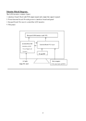
Monitor Block Diagram The LCD monitor contains 4 parts: 1. Power/inverter board: Provide power to control the LCD monitor. 4. Flat panel: Flat panel (LVDS interface) and CCFL Inverter/Power BD (Including AC/DC Power Supply and Inverter) Interface Board (VGA input) Keypad BD AC input Range 90V~264V Host computer (VGA signal input and DDC) 12 Keypad board: For user to interface board and panel 3. interface board: Deal with VGA input signal and output the signal to panel. 2.
Monitor Block Diagram The LCD monitor contains 4 parts: 1. Power/inverter board: Provide power to control the LCD monitor. 4. Flat panel: Flat panel (LVDS interface) and CCFL Inverter/Power BD (Including AC/DC Power Supply and Inverter) Interface Board (VGA input) Keypad BD AC input Range 90V~264V Host computer (VGA signal input and DDC) 12 Keypad board: For user to interface board and panel 3. interface board: Deal with VGA input signal and output the signal to panel. 2.
AL1706 Service Guide
Page 25
...following a time-out period, will automatically switch to the host that continuously transmits EDID information. USING RIGHT POWER CORD The accessory power cord for the power cord shall be 125 volts AC. 25 The voltage rating for the Northern American region is the wallet plug...VESA) and/or the United States Environmental Protection Agency (EPA) and the Swedish Confederation Employees (NUTEK). This reduces the monitor's internal power supply consumption. The communication channel is automatically redrawn. It allows the monitor to conserve electrical energy by pressing a key on the I2C ...
...following a time-out period, will automatically switch to the host that continuously transmits EDID information. USING RIGHT POWER CORD The accessory power cord for the power cord shall be 125 volts AC. 25 The voltage rating for the Northern American region is the wallet plug...VESA) and/or the United States Environmental Protection Agency (EPA) and the Swedish Confederation Employees (NUTEK). This reduces the monitor's internal power supply consumption. The communication channel is automatically redrawn. It allows the monitor to conserve electrical energy by pressing a key on the I2C ...
AL1706 Service Guide
Page 34
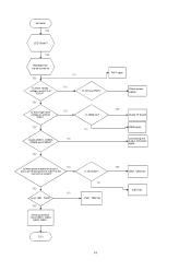
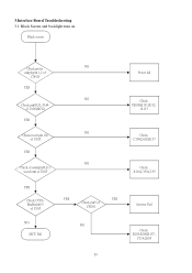
... there 12Vdc voltage on pin1, pin3, pin15 and pin16 of IC501 at the moment of restart? No raster YES LED Green? NO F501 open Check power supply YES Check I/F board R526 open Connecting the output connector again NO Is there pulse waveform on pin13 of IC501 YES Check CN501, CN502, CN503 and...
... there 12Vdc voltage on pin1, pin3, pin15 and pin16 of IC501 at the moment of restart? No raster YES LED Green? NO F501 open Check power supply YES Check I/F board R526 open Connecting the output connector again NO Is there pulse waveform on pin13 of IC501 YES Check CN501, CN502, CN503 and...
AL1706 Service Guide
Page 35
3.Interface Board Troubleshooting 3.1 Black Screen and backlight turn on Black screen Check power NG supply:pin 1,2 of CN101 YES NG Check pin30,31,35,44 of U105(MCU) YES NG Check reset (pin 10) of U105 YES NG Check crystal(pin20,21) waveform of U105 YES Check CCFLEnable(pin3) of U105 NG MCU Fail YES YES Check pin5 of CN101 NG Power fail Check FB108,R131,R132, R133 Check C150,D102,R137 Check X101,C154,C155 Inverter Fail Check R105,R106,R157, C114,Q103 35
3.Interface Board Troubleshooting 3.1 Black Screen and backlight turn on Black screen Check power NG supply:pin 1,2 of CN101 YES NG Check pin30,31,35,44 of U105(MCU) YES NG Check reset (pin 10) of U105 YES NG Check crystal(pin20,21) waveform of U105 YES Check CCFLEnable(pin3) of U105 NG MCU Fail YES YES Check pin5 of CN101 NG Power fail Check FB108,R131,R132, R133 Check C150,D102,R137 Check X101,C154,C155 Inverter Fail Check R105,R106,R157, C114,Q103 35
AL1706 User's Guide
Page 5
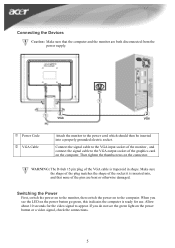
...the monitor to the monitor, then switch the power on the computer. Connect the signal cable to the VGA input socket of the monitor , and connect the signal cable to the VGA output socket of the pins are both disconnected from the power supply. If you see the green light on ...the power button or a video signal, check the connections. 5 Then tighten the thumbscrews on the power button go green, this indicates the computer is ready for the video signal ...
...the monitor to the monitor, then switch the power on the computer. Connect the signal cable to the VGA input socket of the monitor , and connect the signal cable to the VGA output socket of the pins are both disconnected from the power supply. If you see the green light on ...the power button or a video signal, check the connections. 5 Then tighten the thumbscrews on the power button go green, this indicates the computer is ready for the video signal ...


