
AL1706 Service Guide
Page 5
... help. Increase the separation between the equipment and receiver. 3. Connect the equipment into an outlet on , the user is connected. 4. Shielded interface cables and AC power cord, if any radio or TV interference caused by one or more of the following measures: 1. The manufacturer is the responsibility of the FCC Rules...
... help. Increase the separation between the equipment and receiver. 3. Connect the equipment into an outlet on , the user is connected. 4. Shielded interface cables and AC power cord, if any radio or TV interference caused by one or more of the following measures: 1. The manufacturer is the responsibility of the FCC Rules...
AL1706 Service Guide
Page 7
... washbowl, kitchen sink, laundry tub, swimming pool or in fire or electric shock. The monitor should be used for ventilation. Do not overload power strips and extension cords. It could short circuit parts causing a fire or electric shock. Do not attempt to qualified service personnel. SPECIAL NOTES ...the monitor only with the monitor. User only a trolley or stand recommended by the manufacturer and following symptoms are provide for long periods of power source indicated on a bed, sofa, rug, or similar surface. If you mount the monitor on an unstable trolley, stand, or table....
... washbowl, kitchen sink, laundry tub, swimming pool or in fire or electric shock. The monitor should be used for ventilation. Do not overload power strips and extension cords. It could short circuit parts causing a fire or electric shock. Do not attempt to qualified service personnel. SPECIAL NOTES ...the monitor only with the monitor. User only a trolley or stand recommended by the manufacturer and following symptoms are provide for long periods of power source indicated on a bed, sofa, rug, or similar surface. If you mount the monitor on an unstable trolley, stand, or table....
AL1706 Service Guide
Page 8
the same image is recovered slowly by changing the image or turning off the Power Switch for hours. In this case, the screen is displayed for hours. 8
the same image is recovered slowly by changing the image or turning off the Power Switch for hours. In this case, the screen is displayed for hours. 8
AL1706 Service Guide
Page 10
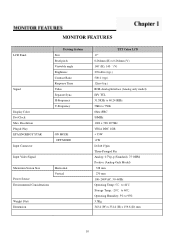
MONITOR FEATURES LCD Panel Signal Display Color Dot Clock Max. H-Frequency V-Frequency ON MODE OFF MODE Input Video Signal Maximum Screen Size Power Source Environmental Considerations Horizontal Vertical Weight (Net) Dimension TFT Color LCD 17" 0.264mm (H) x 0.264mm (V) 140゚(H), 140 ゚(V) 270cd/m2 (typ.) 500:1 (typ.) 12ms (typ.) ...
MONITOR FEATURES LCD Panel Signal Display Color Dot Clock Max. H-Frequency V-Frequency ON MODE OFF MODE Input Video Signal Maximum Screen Size Power Source Environmental Considerations Horizontal Vertical Weight (Net) Dimension TFT Color LCD 17" 0.264mm (H) x 0.264mm (V) 140゚(H), 140 ゚(V) 270cd/m2 (typ.) 500:1 (typ.) 12ms (typ.) ...
AL1706 Service Guide
Page 12
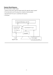
Keypad board: For user to panel. 2. Monitor Block Diagram The LCD monitor contains 4 parts: 1. interface board: Deal with VGA input signal and output the signal to control the LCD monitor. 4. Flat panel: Flat panel (LVDS interface) and CCFL Inverter/Power BD (Including AC/DC Power Supply and Inverter) Interface Board (VGA input) Keypad BD AC input Range 90V~264V Host computer (VGA signal input and DDC) 12 Power/inverter board: Provide power to interface board and panel 3.
Keypad board: For user to panel. 2. Monitor Block Diagram The LCD monitor contains 4 parts: 1. interface board: Deal with VGA input signal and output the signal to control the LCD monitor. 4. Flat panel: Flat panel (LVDS interface) and CCFL Inverter/Power BD (Including AC/DC Power Supply and Inverter) Interface Board (VGA input) Keypad BD AC input Range 90V~264V Host computer (VGA signal input and DDC) 12 Power/inverter board: Provide power to interface board and panel 3.
AL1706 Service Guide
Page 16
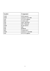
Symbol: CN103 CN101 U102 X102 U104 U105 CN102 U103 U106 X101 CN105 U101 Component: LVDS connector Connector to power BD 5V to 1.8V regulator Crystal to scaler Scaler "TSU16AK" MCU "Winbond" D-sub connector DDC EEPROM Crystal to MCU Connector to control BD 5V to 3.3V regulator 16
Symbol: CN103 CN101 U102 X102 U104 U105 CN102 U103 U106 X101 CN105 U101 Component: LVDS connector Connector to power BD 5V to 1.8V regulator Crystal to scaler Scaler "TSU16AK" MCU "Winbond" D-sub connector DDC EEPROM Crystal to MCU Connector to control BD 5V to 3.3V regulator 16
AL1706 Service Guide
Page 18
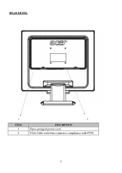
REAR BEZEL 1 ITEM 1 2 2 DESCRIPTION Three-pronged power cord VGA Cable with blue connector compliance with PC99 18
REAR BEZEL 1 ITEM 1 2 2 DESCRIPTION Three-pronged power cord VGA Cable with blue connector compliance with PC99 18
AL1706 Service Guide
Page 19
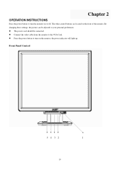
By changing these settings, the picture can be connected. Press the power button to turn the monitor on the monitor, the power indicator will light up. Chapter 2 OPERATION INSTRUCTIONS Press the power button to turn on or off. Connect the video cable from the monitor to your personal preferences. Front Panel Control 5 4 3 2 1 19 The other control buttons are located on the front of the monitor. The power cord should be adjusted to the VGA Card.
By changing these settings, the picture can be connected. Press the power button to turn the monitor on the monitor, the power indicator will light up. Chapter 2 OPERATION INSTRUCTIONS Press the power button to turn on or off. Connect the video cable from the monitor to your personal preferences. Front Panel Control 5 4 3 2 1 19 The other control buttons are located on the front of the monitor. The power cord should be adjusted to the VGA Card.
AL1706 Service Guide
Page 20
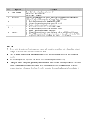
No Symbol 1 Power key/LED 2 Menu/Enter 3 > 4 < 5 Auto/Exit Function Press this button to ship your monitor as it . 20 Off mode Activate OSD menu when OSD is ... is ON. 3. Navigate through adjustments icons when OSD is activated. 1. Save the original shipping carton and packing materials, as they will come in the factory. Power On mode LED Orange - Never use strong solvents such as thinner, benzene, or abrasive cleaners, since these will act as radiators or air ducts, or...
No Symbol 1 Power key/LED 2 Menu/Enter 3 > 4 < 5 Auto/Exit Function Press this button to ship your monitor as it . 20 Off mode Activate OSD menu when OSD is ... is ON. 3. Navigate through adjustments icons when OSD is activated. 1. Save the original shipping carton and packing materials, as they will come in the factory. Power On mode LED Orange - Never use strong solvents such as thinner, benzene, or abrasive cleaners, since these will act as radiators or air ducts, or...
AL1706 Service Guide
Page 24
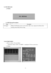
2) OSD MESSAGE a. b. Outline b. Outline 24 OSD Message Description Item Description No Signal When LCD Monitor power on, but video cable is not connected, will show this message, then enter power saving. 3) FACTORY MENU a. How to call out "Factory Menu" At VGA in, Push "AUTO" & "MENU", and plug AC Power cord in sync..
2) OSD MESSAGE a. b. Outline b. Outline 24 OSD Message Description Item Description No Signal When LCD Monitor power on, but video cable is not connected, will show this message, then enter power saving. 3) FACTORY MENU a. How to call out "Factory Menu" At VGA in, Push "AUTO" & "MENU", and plug AC Power cord in sync..
AL1706 Service Guide
Page 25
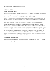
...VIDEO INPUT SIGNAL. The appearance is similar to a "Screen Saver" feature except the display is automatically redrawn. USING RIGHT POWER CORD The accessory power cord for the power cord shall be 125 volts AC. 25 The voltage rating for the Northern American region is the wallet plug with VESA... system its identity and, depending on the keyboard, or clicking the mouse. This feature is designed to conserve electrical energy by reducing power consumption when there is a unidirectional data channel from the display to the VESA DDC STANDARD. The display is a bidirectional data channel ...
...VIDEO INPUT SIGNAL. The appearance is similar to a "Screen Saver" feature except the display is automatically redrawn. USING RIGHT POWER CORD The accessory power cord for the power cord shall be 125 volts AC. 25 The voltage rating for the Northern American region is the wallet plug with VESA... system its identity and, depending on the keyboard, or clicking the mouse. This feature is designed to conserve electrical energy by reducing power consumption when there is a unidirectional data channel from the display to the VESA DDC STANDARD. The display is a bidirectional data channel ...
AL1706 Service Guide
Page 26
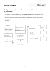
NOTE: 1. The monitor surface is susceptible to avoid mismatch when putting back the components. 2. Wear gloves Chassis*1 PCBA Power Board *1 INSULATOR PC,MYLAR SCREW (PW 3*6,M,ZN) *3 PCBA I/F BOARD *1 CABLE 30P FFC HRN ASS'Y 8P SCREW (PW 3*6,M,ZN) *3 INL Panel*1 SCREW (PW3x4,M,ZN)*4 FFC(30pin)*1 ...
NOTE: 1. The monitor surface is susceptible to avoid mismatch when putting back the components. 2. Wear gloves Chassis*1 PCBA Power Board *1 INSULATOR PC,MYLAR SCREW (PW 3*6,M,ZN) *3 PCBA I/F BOARD *1 CABLE 30P FFC HRN ASS'Y 8P SCREW (PW 3*6,M,ZN) *3 INL Panel*1 SCREW (PW3x4,M,ZN)*4 FFC(30pin)*1 ...
AL1706 Service Guide
Page 30
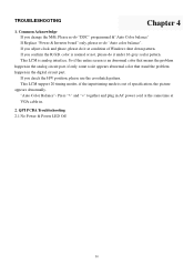
... timing mode is normal or not, please do "Auto color balance". If you change the M/B, Please re-do "DDC" programmed &"Auto Color balance" If Replace "Power & Inverter board" only, please re-do it at condition of specification, the picture appears abnormally.
... timing mode is normal or not, please do "Auto color balance". If you change the M/B, Please re-do "DDC" programmed &"Auto Color balance" If Replace "Power & Inverter board" only, please re-do it at condition of specification, the picture appears abnormally.

AL1706 Service Guide
Page 31
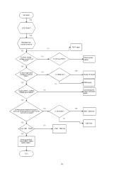
No power &LED off YES Check primary rectifier voltage NO NO Check circuit if short Check IC802, C805, T801 YES Check pin3 of IC802 voltage about 1V YES Check F801, F802, P801, D801 NO Check R801, R805, R822, R823, R817 YES Check pin2 of IC802 voltage about 2V YES NO Check R803, R807, R824, R825 Check pin1 of IC802 voltage is 5.8V NO Check R812, R816, C818 YES END 2.2 DC output voltage is unstable 31
No power &LED off YES Check primary rectifier voltage NO NO Check circuit if short Check IC802, C805, T801 YES Check pin3 of IC802 voltage about 1V YES Check F801, F802, P801, D801 NO Check R801, R805, R822, R823, R817 YES Check pin2 of IC802 voltage about 2V YES NO Check R803, R807, R824, R825 Check pin1 of IC802 voltage is 5.8V NO Check R812, R816, C818 YES END 2.2 DC output voltage is unstable 31

AL1706 Service Guide
Page 33
2.3 Output power is unstable Unstable power Check sampling Circuit YES Check the R pin voltage of IC803 about 2.5V YES Check pin1 of IC802 voltage is 5.8V NO Check R810, R811,R818 NO Check the C pin voltage of IC803 if 3V YES Check R809, R808, R814, D809 NO Check D806, C815 if short NO Change R810, R811, R818 NO Change IC803 Change D806, C815 YES Check pin3 of IC802 voltage about 1V YES END NO Change R801, R805, R822, R823, R817 2.4 Backlight can't be turned on 33
2.3 Output power is unstable Unstable power Check sampling Circuit YES Check the R pin voltage of IC803 about 2.5V YES Check pin1 of IC802 voltage is 5.8V NO Check R810, R811,R818 NO Check the C pin voltage of IC803 if 3V YES Check R809, R808, R814, D809 NO Check D806, C815 if short NO Change R810, R811, R818 NO Change IC803 Change D806, C815 YES Check pin3 of IC802 voltage about 1V YES END NO Change R801, R805, R822, R823, R817 2.4 Backlight can't be turned on 33
AL1706 Service Guide
Page 34
... Is Ok fuse F501? YES NO Is ok T501, T502? YES Check protected circuit Q501, Q502, Q503, Q504 Is Ok IC501? NO F501 open Check power supply YES Check I/F board R526 open Connecting the output connector again NO Is there pulse waveform on pin1, pin3, pin15 and pin16 of IC501 at...
... Is Ok fuse F501? YES NO Is ok T501, T502? YES Check protected circuit Q501, Q502, Q503, Q504 Is Ok IC501? NO F501 open Check power supply YES Check I/F board R526 open Connecting the output connector again NO Is there pulse waveform on pin1, pin3, pin15 and pin16 of IC501 at...
AL1706 Service Guide
Page 35
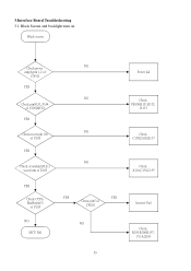
3.Interface Board Troubleshooting 3.1 Black Screen and backlight turn on Black screen Check power NG supply:pin 1,2 of CN101 YES NG Check pin30,31,35,44 of U105(MCU) YES NG Check reset (pin 10) of U105 YES NG Check crystal(pin20,21) waveform of U105 YES Check CCFLEnable(pin3) of U105 NG MCU Fail YES YES Check pin5 of CN101 NG Power fail Check FB108,R131,R132, R133 Check C150,D102,R137 Check X101,C154,C155 Inverter Fail Check R105,R106,R157, C114,Q103 35
3.Interface Board Troubleshooting 3.1 Black Screen and backlight turn on Black screen Check power NG supply:pin 1,2 of CN101 YES NG Check pin30,31,35,44 of U105(MCU) YES NG Check reset (pin 10) of U105 YES NG Check crystal(pin20,21) waveform of U105 YES Check CCFLEnable(pin3) of U105 NG MCU Fail YES YES Check pin5 of CN101 NG Power fail Check FB108,R131,R132, R133 Check C150,D102,R137 Check X101,C154,C155 Inverter Fail Check R105,R106,R157, C114,Q103 35

AL1706 Service Guide
Page 39
Process To Access Factory Mode Power Off Press "AUTO"& "MENU"buttons at the same time Power On Release the "AUTO"& "MENU" buttons Press "MENU" Button Press "
Process To Access Factory Mode Power Off Press "AUTO"& "MENU"buttons at the same time Power On Release the "AUTO"& "MENU" buttons Press "MENU" Button Press "
AL1706 Service Guide
Page 41
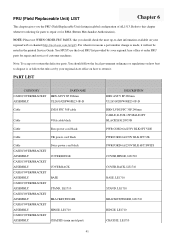
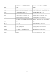
... the defective parts. FRU (Field Replaceable Unit) LIST Chapter 6 This chapter gives you should follow the rules set by your regional Acer office on how to repair or for RMA (Return Merchandise Authorization). Refer to this chapter whenever ordering for repair and service of AL1513.../BRACKET ASSEMBLY CASE/COVER/BRACKET ASSEMBLY CASE/COVER/BRACKET ASSEMBLY CASE/COVER/BRACKET ASSEMBLY CASE/COVER/BRACKET ASSEMBLY CASE/COVER/BRACKET ASSEMBLY Swiss power cord black COVER,HINGE COVER,BACK BASE STAND, LE1710 BRACKET,FINGER HINGE, LE1710 CHASSIS (main metal part) 41 DESCRIPTION HRN ASS'Y...
... the defective parts. FRU (Field Replaceable Unit) LIST Chapter 6 This chapter gives you should follow the rules set by your regional Acer office on how to repair or for RMA (Return Merchandise Authorization). Refer to this chapter whenever ordering for repair and service of AL1513.../BRACKET ASSEMBLY CASE/COVER/BRACKET ASSEMBLY CASE/COVER/BRACKET ASSEMBLY CASE/COVER/BRACKET ASSEMBLY CASE/COVER/BRACKET ASSEMBLY CASE/COVER/BRACKET ASSEMBLY Swiss power cord black COVER,HINGE COVER,BACK BASE STAND, LE1710 BRACKET,FINGER HINGE, LE1710 CHASSIS (main metal part) 41 DESCRIPTION HRN ASS'Y...
AL1706 Service Guide
Page 42
...,P,CROSS W/WAS,M3*6,Zn FOIL,AL.,DOUBLE COND.,45x35x0.04mm, FOIL,AL.,DOUBLE COND.,45x35x0.04mm, LE17 LE17 main board PCBA,IF BOARD, LE1710-6A0 power + invertor board LCD PANEL 17" MT170EN01-V1-G3AM170000512 PCBA,PWR&INV./B, LE1710-6A0 LCD PANEL 17" MT170EN01-V1-G3AM170000512 Key pad PCBA,KEYPAD BOARD+ Bezel...
...,P,CROSS W/WAS,M3*6,Zn FOIL,AL.,DOUBLE COND.,45x35x0.04mm, FOIL,AL.,DOUBLE COND.,45x35x0.04mm, LE17 LE17 main board PCBA,IF BOARD, LE1710-6A0 power + invertor board LCD PANEL 17" MT170EN01-V1-G3AM170000512 PCBA,PWR&INV./B, LE1710-6A0 LCD PANEL 17" MT170EN01-V1-G3AM170000512 Key pad PCBA,KEYPAD BOARD+ Bezel...


