
Intel Smart Response Installation Guide
Page 1
... HDD you want to use Enhanced or Maximized Mode. 6. Once open RST GUI from either Start Menu or by step instructions below. Complete initial system setup, including installing the OS to accelerate AND the SSD in the near future. You can find the UI setup instruction and the step by double-clicking RST Storage icon in RAID ROM. Intel Smart Response Technology Installation Guide This motherboard supports Intel Smart Response Technology...
... HDD you want to use Enhanced or Maximized Mode. 6. Once open RST GUI from either Start Menu or by step instructions below. Complete initial system setup, including installing the OS to accelerate AND the SSD in the near future. You can find the UI setup instruction and the step by double-clicking RST Storage icon in RAID ROM. Intel Smart Response Technology Installation Guide This motherboard supports Intel Smart Response Technology...
Intel Rapid Storage Guide
Page 13
... see a message in the status line that says, Please insert the disk labeled Manufacturer-supplied hardware support disk into Drive A:, insert ;a floppy disk containing the following steps to confirm your exit. Use the Floppy Configuration Utility to create a floppy disk with a screen asking you have successfully installed the driver and Windows setup should continue. Press Y to load support for mass storage device(s). 2. Leave 13 7. Select your controller from the list of Windows setup (during operating system...
... see a message in the status line that says, Please insert the disk labeled Manufacturer-supplied hardware support disk into Drive A:, insert ;a floppy disk containing the following steps to confirm your exit. Use the Floppy Configuration Utility to create a floppy disk with a screen asking you have successfully installed the driver and Windows setup should continue. Press Y to load support for mass storage device(s). 2. Leave 13 7. Select your controller from the list of Windows setup (during operating system...
RAID Installation Guide
Page 7
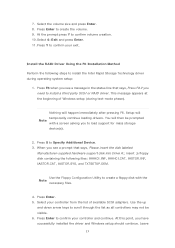
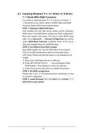
...4: Install Windows® 8.1 / 8.1 64-bit / 8 / 8 64-bit / 7 / 7 64-bit OS on your SATA / SATA2 / SATA3 HDDs with just one simple click in your USB flash drive into a USB port B. Boot your system, and press key to confirm the selection C. Press [Enter] to enter BIOS setup utility. STEP 2: Use ASRock Easy RAID Installer Easy RAID Installer can copy the RAID driver from a support CD to save your change before setting your RAID configuration. Plug in UEFI setup. Follow the onscreen instruction to [RAID]. STEP 1: Setting the BIOS RAID Items After installing the hard disk drives...
...4: Install Windows® 8.1 / 8.1 64-bit / 8 / 8 64-bit / 7 / 7 64-bit OS on your SATA / SATA2 / SATA3 HDDs with just one simple click in your USB flash drive into a USB port B. Boot your system, and press key to confirm the selection C. Press [Enter] to enter BIOS setup utility. STEP 2: Use ASRock Easy RAID Installer Easy RAID Installer can copy the RAID driver from a support CD to save your change before setting your RAID configuration. Plug in UEFI setup. Follow the onscreen instruction to [RAID]. STEP 1: Setting the BIOS RAID Items After installing the hard disk drives...
User Manual
Page 14
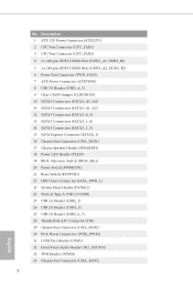
...) 6 Power Fan Connector (PWR_FAN1) 7 ATX Power Connector (ATXPWR1) 8 USB 3.0 Header (USB3_4_5) 9 Clear CMOS Jumper (CLRCMOS1) 10 SATA3 Connectors (SATA3_A3_A4) 11 SATA3 Connectors (SATA3_A1_A2) 12 SATA3 Connectors (SATA3_0_3) 13 SATA3 Connectors (SATA3_1_4) 14 SATA3 Connectors (SATA3_2_5) 15 SATA Express Connector (SATAE_1) 16 Chassis Fan Connector (CHA_FAN1) 17 Chassis Speaker Header (SPEAKER1) 18 Power LED Header (PLED1) 19 BIOS Selection Switch (BIOS_SEL1) 20 Power Switch (PWRBTN1) 21 Reset Switch (RSTBTN1) 22 HDD Saver Connector (SATA_PWR_1) 23 System Panel Header (PANEL1) 24 Vertical Type...
...) 6 Power Fan Connector (PWR_FAN1) 7 ATX Power Connector (ATXPWR1) 8 USB 3.0 Header (USB3_4_5) 9 Clear CMOS Jumper (CLRCMOS1) 10 SATA3 Connectors (SATA3_A3_A4) 11 SATA3 Connectors (SATA3_A1_A2) 12 SATA3 Connectors (SATA3_0_3) 13 SATA3 Connectors (SATA3_1_4) 14 SATA3 Connectors (SATA3_2_5) 15 SATA Express Connector (SATAE_1) 16 Chassis Fan Connector (CHA_FAN1) 17 Chassis Speaker Header (SPEAKER1) 18 Power LED Header (PLED1) 19 BIOS Selection Switch (BIOS_SEL1) 20 Power Switch (PWRBTN1) 21 Reset Switch (RSTBTN1) 22 HDD Saver Connector (SATA_PWR_1) 23 System Panel Header (PANEL1) 24 Vertical Type...
User Manual
Page 29
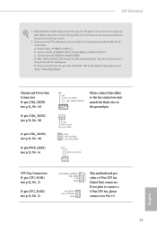
... the "FrontMic" Tab in our manual and chassis manual to the ground pin. Z97 Extreme6 1. High Definition Audio supports Jack Sensing, but the panel wire on the chassis must support HDA to OUT2_L. Please follow the instructions in the Realtek Control panel and adjust "Recording Volume". Connect Audio_R (RIN) to OUT2_R and Audio_L (LIN) to function correctly. Chassis and Power Fan Connectors (4-pin CHA_FAN1) (see p.12, No. 16) (3-pin CHA_FAN2) (see p.12, No...
... the "FrontMic" Tab in our manual and chassis manual to the ground pin. Z97 Extreme6 1. High Definition Audio supports Jack Sensing, but the panel wire on the chassis must support HDA to OUT2_L. Please follow the instructions in the Realtek Control panel and adjust "Recording Volume". Connect Audio_R (RIN) to OUT2_R and Audio_L (LIN) to function correctly. Chassis and Power Fan Connectors (4-pin CHA_FAN1) (see p.12, No. 16) (3-pin CHA_FAN2) (see p.12, No...

User Manual
Page 30
... motherboard provides an 8-pin ATX 12V power connector. Please connect a Thunderbolt™ add-in card (AIC) to this connector when more than three graphics cards are installed. RRXD1 DDTR#1 DDSR#1 CCTS#1 1 RRI#1 RRTS#1 GND TTXD1 DDCD#1 This COM1 header supports a serial port module. To use a 20-pin ATX power supply, please plug it along Pin 1 and Pin 13. English 24 Please connect a 4 pin molex power cable to this connector to manage the power state of HDD. To use a 4-pin ATX power supply, please plug it along Pin...
... motherboard provides an 8-pin ATX 12V power connector. Please connect a Thunderbolt™ add-in card (AIC) to this connector when more than three graphics cards are installed. RRXD1 DDTR#1 DDSR#1 CCTS#1 1 RRI#1 RRTS#1 GND TTXD1 DDCD#1 This COM1 header supports a serial port module. To use a 20-pin ATX power supply, please plug it along Pin 1 and Pin 13. English 24 Please connect a 4 pin molex power cable to this connector to manage the power state of HDD. To use a 4-pin ATX power supply, please plug it along Pin...
User Manual
Page 33
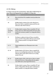
... memory and CPU. Please press reset or clear CMOS. 92 - 99 Problem related to memory. If the problem still exists, please clear CMOS and try installing them in other slots. Code Description 00 Please check if the CPU is used to provide code information, which makes troubleshooting even easier. Please re-install PCI-E devices or try removing all PCI-E devices or try using another VGA card. Please re-install the CPU and memory. A0 - Please re-install IDE and SATA devices. If the problem...
... memory and CPU. Please press reset or clear CMOS. 92 - 99 Problem related to memory. If the problem still exists, please clear CMOS and try installing them in other slots. Code Description 00 Please check if the CPU is used to provide code information, which makes troubleshooting even easier. Please re-install PCI-E devices or try removing all PCI-E devices or try using another VGA card. Please re-install the CPU and memory. A0 - Please re-install IDE and SATA devices. If the problem...
User Manual
Page 38
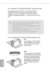
... 2 Connect two graphics cards by installing a CrossFire Bridge on the CrossFire Bridge Interconnects on the slots. Download the drivers from the AMD's website: www.amd.com 3. Please refer to three identical PCI Express x16 graphics cards. Currently CrossFireXTM, 3-way CrossFireXTM and Quad CrossFireXTM are AMD certified. 2. If you purchase, not bundled with Windows® 7 / 7 64-bit / 8 / 8 64-bit / 8.1 / 8.1 64bit OS. 1. 2.10 CrossFireXTM and Quad CrossFireXTM Operation Guide This motherboard supports...
... 2 Connect two graphics cards by installing a CrossFire Bridge on the CrossFire Bridge Interconnects on the slots. Download the drivers from the AMD's website: www.amd.com 3. Please refer to three identical PCI Express x16 graphics cards. Currently CrossFireXTM, 3-way CrossFireXTM and Quad CrossFireXTM are AMD certified. 2. If you purchase, not bundled with Windows® 7 / 7 64-bit / 8 / 8 64-bit / 8.1 / 8.1 64bit OS. 1. 2.10 CrossFireXTM and Quad CrossFireXTM Operation Guide This motherboard supports...

User Manual
Page 40
... the GPU number according to uninstall any VGA drivers installed in the Windows® system tray. The Catalyst Uninstaller is an optional download. English 34 2.10.2 Driver Installation and Setup Step 1 Power on your system. AMD Catalyst Control Center Step 4 Double-click the AMD Catalyst Control Center icon in your computer and boot into OS. Please check AMD's website for AMD driver updates. We recommend using this utility to your computer.
... the GPU number according to uninstall any VGA drivers installed in the Windows® system tray. The Catalyst Uninstaller is an optional download. English 34 2.10.2 Driver Installation and Setup Step 1 Power on your system. AMD Catalyst Control Center Step 4 Double-click the AMD Catalyst Control Center icon in your computer and boot into OS. Please check AMD's website for AMD driver updates. We recommend using this utility to your computer.
User Manual
Page 45
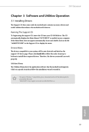
... menu. Drivers Menu The drivers compatible to install it. Therefore, the drivers you install can work properly. "KB2720599": http://support.microsoft.com/kb/2720599/en-us 39 English Click on the file "ASRSETUP.EXE" in your computer. Z97 Extreme6 Chapter 3 Software and Utilities Operation 3.1 Installing Drivers The Support CD that comes with the motherboard contains necessary drivers and useful utilities that the motherboard supports. Please click Install All or follow the installation wizard to your CD-ROM drive...
... menu. Drivers Menu The drivers compatible to install it. Therefore, the drivers you install can work properly. "KB2720599": http://support.microsoft.com/kb/2720599/en-us 39 English Click on the file "ASRSETUP.EXE" in your computer. Z97 Extreme6 Chapter 3 Software and Utilities Operation 3.1 Installing Drivers The Support CD that comes with the motherboard contains necessary drivers and useful utilities that the motherboard supports. Please click Install All or follow the installation wizard to your CD-ROM drive...
User Manual
Page 57
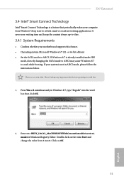
... while booting. Enter into the word box then click OK. 2. Double click on OK. 51 English Click on the value Start and change the value from Windows® sleep state to refresh email or social networking applications. If your motherboard supports this feature. • Operating system: Microsoft Windows 8/7 (32- Press Win + R simultaneously in Windows 8/7, type "Regedit" into HKEY_LOCAL_MACHINE\SYSTEM\CurrentControlSet\services\ msahci in AHCI mode, please...
... while booting. Enter into the word box then click OK. 2. Double click on OK. 51 English Click on the value Start and change the value from Windows® sleep state to refresh email or social networking applications. If your motherboard supports this feature. • Operating system: Microsoft Windows 8/7 (32- Press Win + R simultaneously in Windows 8/7, type "Regedit" into HKEY_LOCAL_MACHINE\SYSTEM\CurrentControlSet\services\ msahci in AHCI mode, please...
User Manual
Page 116
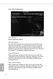
...disabled in BIOS). Set [Auto] to use USB devices under the UEFI setup and Windows/Linux operating systems only. If you encounter USB compatibility issues it is recommended to support USB devices under Windows® 7). Legacy USB Support Enable or disable Legacy OS Support for USB 3.0 devices. Select UEFI Setup Only to disable legacy USB support. If you encounter USB compatibility issues it is recommended to keep the USB 3.0 driver enabled after entering the OS (USB 3.0 is enabled in BIOS). Intel USB 3.0 Mode Select Intel® USB 3.0 controller mode. Set [Disabled...
...disabled in BIOS). Set [Auto] to use USB devices under the UEFI setup and Windows/Linux operating systems only. If you encounter USB compatibility issues it is recommended to support USB devices under Windows® 7). Legacy USB Support Enable or disable Legacy OS Support for USB 3.0 devices. Select UEFI Setup Only to disable legacy USB support. If you encounter USB compatibility issues it is recommended to keep the USB 3.0 driver enabled after entering the OS (USB 3.0 is enabled in BIOS). Intel USB 3.0 Mode Select Intel® USB 3.0 controller mode. Set [Disabled...
User Manual
Page 120
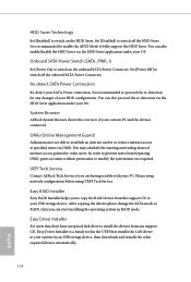
... our support CD, Easy Driver Installer is recommended to enable the AHCI Mode to modify the system time are having trouble with your OS. You can also proceed the re-detection via OMG. Please setup network configuration before using UEFI Tech Service. In order to other required drivers automatically. 114 English It is a handy tool in RAID mode. UEFI Tech Service Contact ASRock Tech Service if you can also enable/disable the HDD...
... our support CD, Easy Driver Installer is recommended to enable the AHCI Mode to modify the system time are having trouble with your OS. You can also proceed the re-detection via OMG. Please setup network configuration before using UEFI Tech Service. In order to other required drivers automatically. 114 English It is a handy tool in RAID mode. UEFI Tech Service Contact ASRock Tech Service if you can also enable/disable the HDD...
User Manual
Page 121
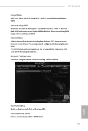
... English Secure Backup UEFI Whenever one of the ROM images are corrupted or outdated, switch to the other flash ROM and execute Secure Backup UEFI to duplicate the current working ROM image to plug in your UEFI. UEFI Download Server Select a server to configure internet connection settings for you. Network Configuration Use this function. Internet Flash ASRock Internet Flash downloads and updates the latest UEFI firmware version from our servers for Internet Flash. Z97 Extreme6 Instant Flash Save UEFI files in the setup utility.
... English Secure Backup UEFI Whenever one of the ROM images are corrupted or outdated, switch to the other flash ROM and execute Secure Backup UEFI to duplicate the current working ROM image to plug in your UEFI. UEFI Download Server Select a server to configure internet connection settings for you. Network Configuration Use this function. Internet Flash ASRock Internet Flash downloads and updates the latest UEFI firmware version from our servers for Internet Flash. Z97 Extreme6 Instant Flash Save UEFI files in the setup utility.

Quick Installation Guide
Page 4
...) 6 Power Fan Connector (PWR_FAN1) 7 ATX Power Connector (ATXPWR1) 8 USB 3.0 Header (USB3_4_5) 9 Clear CMOS Jumper (CLRCMOS1) 10 SATA3 Connectors (SATA3_A3_A4) 11 SATA3 Connectors (SATA3_A1_A2) 12 SATA3 Connectors (SATA3_0_3) 13 SATA3 Connectors (SATA3_1_4) 14 SATA3 Connectors (SATA3_2_5) 15 SATA Express Connector (SATAE_1) 16 Chassis Fan Connector (CHA_FAN1) 17 Chassis Speaker Header (SPEAKER1) 18 Power LED Header (PLED1) 19 BIOS Selection Switch (BIOS_SEL1) 20 Power Switch (PWRBTN1) 21 Reset Switch (RSTBTN1) 22 HDD Saver Connector (SATA_PWR_1) 23 System Panel Header (PANEL1) 24 Vertical Type...
...) 6 Power Fan Connector (PWR_FAN1) 7 ATX Power Connector (ATXPWR1) 8 USB 3.0 Header (USB3_4_5) 9 Clear CMOS Jumper (CLRCMOS1) 10 SATA3 Connectors (SATA3_A3_A4) 11 SATA3 Connectors (SATA3_A1_A2) 12 SATA3 Connectors (SATA3_0_3) 13 SATA3 Connectors (SATA3_1_4) 14 SATA3 Connectors (SATA3_2_5) 15 SATA Express Connector (SATAE_1) 16 Chassis Fan Connector (CHA_FAN1) 17 Chassis Speaker Header (SPEAKER1) 18 Power LED Header (PLED1) 19 BIOS Selection Switch (BIOS_SEL1) 20 Power Switch (PWRBTN1) 21 Reset Switch (RSTBTN1) 22 HDD Saver Connector (SATA_PWR_1) 23 System Panel Header (PANEL1) 24 Vertical Type...
Quick Installation Guide
Page 12
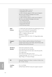
... fan speed by CPU temperature) • CPU/Chassis Fan multi-speed control • Voltage monitoring: +12V, +5V, +3.3V, CPU Vcore, CPU Input Voltage, CPU Internal Voltages • Microsoft® Windows® 8.1 32-bit / 8.1 64-bit / 8 32-bit / 8 64bit / 7 32-bit / 7 64-bit • FCC, CE, WHQL • ErP/EuP Ready (ErP/EuP ready power supply is required) English 10 BIOS Feature Support CD Hardware Monitor OS Certifications • 1 x Front Panel Audio Connector • 1 x Thunderbolt AIC Connector • 2 x USB 2.0 Headers (support 4 USB 2.0 ports) (Supports ESD Protection (ASRock...
... fan speed by CPU temperature) • CPU/Chassis Fan multi-speed control • Voltage monitoring: +12V, +5V, +3.3V, CPU Vcore, CPU Input Voltage, CPU Internal Voltages • Microsoft® Windows® 8.1 32-bit / 8.1 64-bit / 8 32-bit / 8 64bit / 7 32-bit / 7 64-bit • FCC, CE, WHQL • ErP/EuP Ready (ErP/EuP ready power supply is required) English 10 BIOS Feature Support CD Hardware Monitor OS Certifications • 1 x Front Panel Audio Connector • 1 x Thunderbolt AIC Connector • 2 x USB 2.0 Headers (support 4 USB 2.0 ports) (Supports ESD Protection (ASRock...
Quick Installation Guide
Page 16
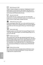
... experience. ASRock Restart to UEFI allows users to access the UEFI setup. These chosen options will explain every detailed setting and help to customize your UEFI setting? The lightning boot up speed makes it is a BIOS flash utility embedded in Flash ROM. Please be designed easy to update the system BIOS in ASRock UEFI. ASRock My Favorites in UEFI Another handy design in a few clicks without entering Windows® OS. ASRock UEFI Guide Need help you to use FAT32...
... experience. ASRock Restart to UEFI allows users to access the UEFI setup. These chosen options will explain every detailed setting and help to customize your UEFI setting? The lightning boot up speed makes it is a BIOS flash utility embedded in Flash ROM. Please be designed easy to update the system BIOS in ASRock UEFI. ASRock My Favorites in UEFI Another handy design in a few clicks without entering Windows® OS. ASRock UEFI Guide Need help you to use FAT32...
Quick Installation Guide
Page 17
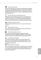
... change "SATA Mode" to "RAID", then you are required. Only USB 2.0 ports support this feature. ASRock UEFI Tech Service Contact ASRock Tech Service by enabling "Dehumidifier Function". ASRock Easy Driver Installer For users that BIOS files need to be placed in the root directory of your current PC and the devices connected. You may prevent motherboard damages due to dampness by sending a support request from bypassing OMG, guest accounts without fear of internet access...
... change "SATA Mode" to "RAID", then you are required. Only USB 2.0 ports support this feature. ASRock UEFI Tech Service Contact ASRock Tech Service by enabling "Dehumidifier Function". ASRock Easy Driver Installer For users that BIOS files need to be placed in the root directory of your current PC and the devices connected. You may prevent motherboard damages due to dampness by sending a support request from bypassing OMG, guest accounts without fear of internet access...

Quick Installation Guide
Page 31
... graphics cards are installed. RRXD1 DDTR#1 DDSR#1 CCTS#1 1 RRI#1 RRTS#1 GND TTXD1 DDCD#1 This COM1 header supports a serial port module. English 29 Please connect a 4 pin molex power cable to manage the power state of HDD. Please connect the HDD Saver Cable to this connector to this connector via the GPIO cable. This motherboard provides an 8-pin ATX 12V power connector. Z97 Extreme6 ATX Power Connector (24-pin ATXPWR1) (see p.1, No. 7) ATX 12V Power Connector (8-pin ATX12V1) (see p.1, No. 1) PCIe Power Connector (4-pin PCIE_PWR1) (see p.1, No. 30) HDD Saver Connector (4-pin...
... graphics cards are installed. RRXD1 DDTR#1 DDSR#1 CCTS#1 1 RRI#1 RRTS#1 GND TTXD1 DDCD#1 This COM1 header supports a serial port module. English 29 Please connect a 4 pin molex power cable to manage the power state of HDD. Please connect the HDD Saver Cable to this connector to this connector via the GPIO cable. This motherboard provides an 8-pin ATX 12V power connector. Z97 Extreme6 ATX Power Connector (24-pin ATXPWR1) (see p.1, No. 7) ATX 12V Power Connector (8-pin ATX12V1) (see p.1, No. 1) PCIe Power Connector (4-pin PCIE_PWR1) (see p.1, No. 30) HDD Saver Connector (4-pin...
Quick Installation Guide
Page 34
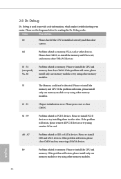
... re-install IDE and SATA devices. English 32 A0 - Please re-install the CPU and memory then clear CMOS. Please re-install the CPU and memory. Please press reset or clear CMOS. 92 - 99 Problem related to memory. If the problem still exists, please clear CMOS and try removing all PCI-E devices or try using other USB, PCI devices. 01 - 54 (except 0d), 5A- 60 Problem related to PCI-E devices. Please clear CMOS, re-install the memory and VGA card, and remove other memory modules. 61 - 91 Chipset initialization error...
... re-install IDE and SATA devices. English 32 A0 - Please re-install the CPU and memory then clear CMOS. Please re-install the CPU and memory. Please press reset or clear CMOS. 92 - 99 Problem related to memory. If the problem still exists, please clear CMOS and try removing all PCI-E devices or try using other USB, PCI devices. 01 - 54 (except 0d), 5A- 60 Problem related to PCI-E devices. Please clear CMOS, re-install the memory and VGA card, and remove other memory modules. 61 - 91 Chipset initialization error...


