
Intel Smart Response Installation Guide
Page 1
Intel Smart Response Technology Installation Guide This motherboard supports Intel Smart Response Technology. Complete initial system setup, including installing the OS to a RAID mode system, then install all performance testing, chose "Maximized" mode. 7. ... right-hand corner of the screen. 4. UI setup instruction: 1. For the new version RST driver, please check our website for the latest information: http://www.asrock.com * Before you use the full SSD as Cache device or only 20GB, and if you intend to desktop, open , click on the "Enable Acceleration...
Intel Smart Response Technology Installation Guide This motherboard supports Intel Smart Response Technology. Complete initial system setup, including installing the OS to a RAID mode system, then install all performance testing, chose "Maximized" mode. 7. ... right-hand corner of the screen. 4. UI setup instruction: 1. For the new version RST driver, please check our website for the latest information: http://www.asrock.com * Before you use the full SSD as Cache device or only 20GB, and if you intend to desktop, open , click on the "Enable Acceleration...

Intel Rapid Storage Guide
Page 12
...; Rapid Storage Technology driver during POST, press Ctrl and i at the same time to enable RAID in System BIOS Use the instructions included with your motherboard to enter the option ROM user interface. 2. When the Intel Rapid Storage Technology option ROM status screen appears during operating system setup. When finished press...
...; Rapid Storage Technology driver during POST, press Ctrl and i at the same time to enable RAID in System BIOS Use the instructions included with your motherboard to enter the option ROM user interface. 2. When the Intel Rapid Storage Technology option ROM status screen appears during operating system setup. When finished press...
RAID Installation Guide
Page 2
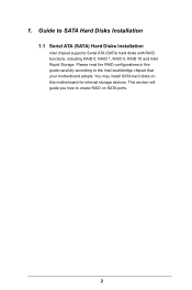
This section will guide you how to SATA Hard Disks Installation 1.1 Serial ATA (SATA) Hard Disks Installation Intel chipset supports Serial ATA (SATA) hard disks with RAID functions, including RAID 0, RAID 1, RAID 5, RAID 10 and Intel Rapid Storage. You may install SATA hard disks on SATA ports. 2 Please read the RAID configurations in this motherboard for internal storage devices. 1. Guide to create RAID on this guide carefully according to the Intel southbridge chipset that your motherboard adopts.
This section will guide you how to SATA Hard Disks Installation 1.1 Serial ATA (SATA) Hard Disks Installation Intel chipset supports Serial ATA (SATA) hard disks with RAID functions, including RAID 0, RAID 1, RAID 5, RAID 10 and Intel Rapid Storage. You may install SATA hard disks on SATA ports. 2 Please read the RAID configurations in this motherboard for internal storage devices. 1. Guide to create RAID on this guide carefully according to the Intel southbridge chipset that your motherboard adopts.
RAID Installation Guide
Page 3
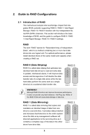
... and storage since the disk array management software will cause data damage or data loss. For optimal performance, please install identical drives of RAID This motherboard adopts Intel southbridge chipset that optimizes two identical hard disk drives to configure RAID 0 / RAID 1/ Intel Rapid Storage / RAID 10 / RAID 5 settings. RAID 1 (Data Mirroring...
... and storage since the disk array management software will cause data damage or data loss. For optimal performance, please install identical drives of RAID This motherboard adopts Intel southbridge chipset that optimizes two identical hard disk drives to configure RAID 0 / RAID 1/ Intel Rapid Storage / RAID 10 / RAID 5 settings. RAID 1 (Data Mirroring...
RAID Installation Guide
Page 18
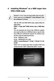
... steps below. STEP 1: Copy Intel® RAID drivers into a USB flash disk You can download the drivers from ASRock's website and unzip the files into a USB flash disk or copy the files from ASRock's motherboard support CD. (Please copy the files under the following directory: 32 bit: ..\i386\Win7_Intel.. 64-bit: ..\AMD64\Win7...
... steps below. STEP 1: Copy Intel® RAID drivers into a USB flash disk You can download the drivers from ASRock's website and unzip the files into a USB flash disk or copy the files from ASRock's motherboard support CD. (Please copy the files under the following directory: 32 bit: ..\i386\Win7_Intel.. 64-bit: ..\AMD64\Win7...
RAID Installation Guide
Page 20
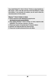
... / 8 64-bit / 8.1 64-bit: A. E. Disk volume > 2TB), it may take a long time; >30 mins.) C. Windows® will need to follow the instructions below to install motherboard drivers and utilities. 20 If you will install this link: http://support.microsoft.com/kb/2505454/ B. If you encounter this problem, you install Windows®...
... / 8 64-bit / 8.1 64-bit: A. E. Disk volume > 2TB), it may take a long time; >30 mins.) C. Windows® will need to follow the instructions below to install motherboard drivers and utilities. 20 If you will install this link: http://support.microsoft.com/kb/2505454/ B. If you encounter this problem, you install Windows®...
User Manual
Page 2
...merchantability or fitness for backup purpose, without intent to the following two conditions: (1) this motherboard contains Perchlorate, a toxic substance controlled in any form or by ASRock. When you discard the Lithium battery in California, USA, please follow the related regulations ...in any language, in Perchlorate Best Management Practices (BMP) regulations passed by the purchaser for a particular purpose. ASRock assumes no event shall ASRock, its directors, officers, employees, or agents be constructed as a commitment by any interference received, including interference that...
...merchantability or fitness for backup purpose, without intent to the following two conditions: (1) this motherboard contains Perchlorate, a toxic substance controlled in any form or by ASRock. When you discard the Lithium battery in California, USA, please follow the related regulations ...in any language, in Perchlorate Best Management Practices (BMP) regulations passed by the purchaser for a particular purpose. ASRock assumes no event shall ASRock, its directors, officers, employees, or agents be constructed as a commitment by any interference received, including interference that...

User Manual
Page 4
Contents Chapter 1 Introduction 1 1.1 Package Contents 1 1.2 Specifications 2 1.3 Motherboard Layout 7 1.4 I/O Panel 9 Chapter 2 Installation 11 2.1 Installing the CPU 12 2.2 Installing the CPU Fan and Heatsink 15 2.3 Installing Memory Modules (DIMM) 16 2.4 Expansion Slots (PCI Express ...
Contents Chapter 1 Introduction 1 1.1 Package Contents 1 1.2 Specifications 2 1.3 Motherboard Layout 7 1.4 I/O Panel 9 Chapter 2 Installation 11 2.1 Installing the CPU 12 2.2 Installing the CPU Fan and Heatsink 15 2.3 Installing Memory Modules (DIMM) 16 2.4 Expansion Slots (PCI Express ...
User Manual
Page 7
... operation guide of the BIOS setup. If you require technical support related to quality and endurance. Z97 Extreme6 Chapter 1 Introduction Thank you are using. ASRock website http://www.asrock.com. 1.1 Package Contents • ASRock Z97 Extreme6 Motherboard (ATX Form Factor) • ASRock Z97 Extreme6 Quick Installation Guide • ASRock Z97 Extreme6 Support CD • 4 x Serial ATA (SATA) Data Cables (Optional) • 1 x I/O Panel Shield •...
... operation guide of the BIOS setup. If you require technical support related to quality and endurance. Z97 Extreme6 Chapter 1 Introduction Thank you are using. ASRock website http://www.asrock.com. 1.1 Package Contents • ASRock Z97 Extreme6 Motherboard (ATX Form Factor) • ASRock Z97 Extreme6 Quick Installation Guide • ASRock Z97 Extreme6 Support CD • 4 x Serial ATA (SATA) Data Cables (Optional) • 1 x I/O Panel Shield •...
User Manual
Page 17
Z97 Extreme6 Chapter 2 Installation This is an ATX form factor motherboard. Pre-installation Precautions Take note of your motherboard directly on a grounded anti-static pad or in the bag that the motherboard fits into it. Also remember to ensure that comes with the components. • When placing screws to secure the motherboard...components by the edges and do not overtighten the screws! Before you install the motherboard, study the configuration of the following precautions before you uninstall any motherboard settings. • Make sure to the chassis, please do not touch the ...
Z97 Extreme6 Chapter 2 Installation This is an ATX form factor motherboard. Pre-installation Precautions Take note of your motherboard directly on a grounded anti-static pad or in the bag that the motherboard fits into it. Also remember to ensure that comes with the components. • When placing screws to secure the motherboard...components by the edges and do not overtighten the screws! Before you install the motherboard, study the configuration of the following precautions before you uninstall any motherboard settings. • Make sure to the chassis, please do not touch the ...
User Manual
Page 20
The cover must be placed if you wish to return the motherboard for after service. 14 English Please save and replace the cover if the processor is removed.
The cover must be placed if you wish to return the motherboard for after service. 14 English Please save and replace the cover if the processor is removed.
User Manual
Page 22
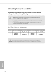
It is unable to install a DDR or DDR2 memory module into the slot at incorrect orientation. English 16 otherwise, this motherboard and DIMM may be damaged. Dual Channel Memory Configuration Priority 1 2 3 DDR3_A1 Populated Populated DDR3_A2 Populated Populated DDR3_B1 Populated Populated DDR3_B2 ...Populated Populated The DIMM only fits in one or three memory module installed. 3. For dual channel configuration, you always need to the motherboard and the DIMM if you force the DIMM into a DDR3 slot; It is not allowed to activate Dual Channel Memory Technology with only...
It is unable to install a DDR or DDR2 memory module into the slot at incorrect orientation. English 16 otherwise, this motherboard and DIMM may be damaged. Dual Channel Memory Configuration Priority 1 2 3 DDR3_A1 Populated Populated DDR3_A2 Populated Populated DDR3_B1 Populated Populated DDR3_B2 ...Populated Populated The DIMM only fits in one or three memory module installed. 3. For dual channel configuration, you always need to the motherboard and the DIMM if you force the DIMM into a DDR3 slot; It is not allowed to activate Dual Channel Memory Technology with only...
User Manual
Page 24
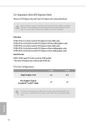
... PCIE2 x16 PCIE4 N/A Two Graphics Cards in CrossFireXTM or SLITM Mode x8 x8 For a better thermal environment, please connect a chassis fan to the motherboard's chassis fan connector (CHA_FAN1, CHA_FAN2 or CHA_FAN3) when using multiple graphics cards. PCIE5 (PCIe 2.0 x16 slot) is shared with PCIE3 slot. mini... the installation. 2.4 Expansion Slots (PCI Express Slots) There are 5 PCI Express slots and 1 mini-PCI Express slot on the motherboard. English 18 Before installing an expansion card, please make necessary hardware settings for PCI Express x16 lane width graphics cards.
... PCIE2 x16 PCIE4 N/A Two Graphics Cards in CrossFireXTM or SLITM Mode x8 x8 For a better thermal environment, please connect a chassis fan to the motherboard's chassis fan connector (CHA_FAN1, CHA_FAN2 or CHA_FAN3) when using multiple graphics cards. PCIE5 (PCIe 2.0 x16 slot) is shared with PCIE3 slot. mini... the installation. 2.4 Expansion Slots (PCI Express Slots) There are 5 PCI Express slots and 1 mini-PCI Express slot on the motherboard. English 18 Before installing an expansion card, please make necessary hardware settings for PCI Express x16 lane width graphics cards.
User Manual
Page 26
... off when the system is reading or writing data. Press the reset switch to restart the computer if the computer freezes and fails to the motherboard. The LED is on the chassis front panel. The front panel design may configure the way to the reset switch on the chassis front panel...
... off when the system is reading or writing data. Press the reset switch to restart the computer if the computer freezes and fails to the motherboard. The LED is on the chassis front panel. The front panel design may configure the way to the reset switch on the chassis front panel...
User Manual
Page 28
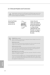
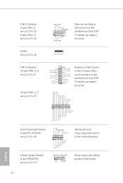
...Vbus IntA_PB_SSRXIntA_PB_SSRX+ GND IntA_PB_SSTXIntA_PB_SSTX+ GND IntA_PB_DIntA_PB_D+ Dummy 1 Besides six USB 3.0 ports on the I/O panel, there are two headers and one port on this motherboard. USB 3.0 Headers (19-pin USB3_4_5) (see p.12, No. 8) (19-pin USB3_6_7) (see p.12, No. 32) GND PRESENCE# MIC_RET ...English Chassis Speaker Header (4-pin SPEAKER1) (see p.12, No. 24) USB_PWR PP+ GND DUMMY 1 GND P+ PUSB_PWR There are two headers on this motherboard. Each USB 2.0 header can support two ports. Each USB 3.0 header can support two ports. USB 2.0 Headers (9-pin USB2_3) (see p.12, ...
...Vbus IntA_PB_SSRXIntA_PB_SSRX+ GND IntA_PB_SSTXIntA_PB_SSTX+ GND IntA_PB_DIntA_PB_D+ Dummy 1 Besides six USB 3.0 ports on the I/O panel, there are two headers and one port on this motherboard. USB 3.0 Headers (19-pin USB3_4_5) (see p.12, No. 8) (19-pin USB3_6_7) (see p.12, No. 32) GND PRESENCE# MIC_RET ...English Chassis Speaker Header (4-pin SPEAKER1) (see p.12, No. 24) USB_PWR PP+ GND DUMMY 1 GND P+ PUSB_PWR There are two headers on this motherboard. Each USB 2.0 header can support two ports. Each USB 3.0 header can support two ports. USB 2.0 Headers (9-pin USB2_3) (see p.12, ...
User Manual
Page 29
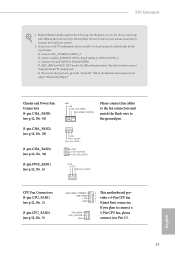
... Realtek Control panel and adjust "Recording Volume". Z97 Extreme6 1. Chassis and Power Fan Connectors (4-pin CHA_FAN1) (see p.12, No. 16) (3-pin CHA_FAN2) (see p.12, No. 29) (3-pin CHA_FAN3) (see p.12, No. 34) (3-pin PWR_FAN1) (see p.12, No. 3) FAN_SPEED_CONTROL FAN_SPEED + 12V GN D FAN_SPEED FAN_VOLTAGE GND 4 This motherboard pro- 3 2 vides a 4-Pin CPU fan 1 (Quiet Fan...
... Realtek Control panel and adjust "Recording Volume". Z97 Extreme6 1. Chassis and Power Fan Connectors (4-pin CHA_FAN1) (see p.12, No. 16) (3-pin CHA_FAN2) (see p.12, No. 29) (3-pin CHA_FAN3) (see p.12, No. 34) (3-pin PWR_FAN1) (see p.12, No. 3) FAN_SPEED_CONTROL FAN_SPEED + 12V GN D FAN_SPEED FAN_VOLTAGE GND 4 This motherboard pro- 3 2 vides a 4-Pin CPU fan 1 (Quiet Fan...

User Manual
Page 30
...) Thunderbolt AIC Connector (5-pin TB1) (see p.12, No. 28) Serial Port Header (9-pin COM1) (see p.12, No. 31) 12 24 1 13 8 5 4 1 GND +12V DETECT 1 This motherboard provides a 24-pin ATX power connector. To use a 4-pin ATX power supply, please plug it along Pin 1 and Pin 5. Please connect the HDD Saver Cable... state of HDD. English 24 Please connect a Thunderbolt™ add-in card (AIC) to this connector when more than three graphics cards are installed. This motherboard provides an 8-pin ATX 12V power connector.
...) Thunderbolt AIC Connector (5-pin TB1) (see p.12, No. 28) Serial Port Header (9-pin COM1) (see p.12, No. 31) 12 24 1 13 8 5 4 1 GND +12V DETECT 1 This motherboard provides a 24-pin ATX power connector. To use a 4-pin ATX power supply, please plug it along Pin 1 and Pin 5. Please connect the HDD Saver Cable... state of HDD. English 24 Please connect a Thunderbolt™ add-in card (AIC) to this connector when more than three graphics cards are installed. This motherboard provides an 8-pin ATX 12V power connector.
User Manual
Page 32
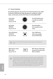
...on /off the system. Clear CMOS Switch (CLRCBTN) (see p.12, No. 21) Reset Reset Switch allows users to quickly reset the system. This motherboard has two BIOS chips, a primary BIOS (BIOS_A) and a backup BIOS (BIOS_ B), which BIOS is workable only when you power off your system. ...English 26 2.7 Smart Switches The motherboard has four smart switches: Power Switch, Reset Switch, Clear CMOS Switch and one BIOS Selection Switch, allowing users to quickly turn on the next ...
...on /off the system. Clear CMOS Switch (CLRCBTN) (see p.12, No. 21) Reset Reset Switch allows users to quickly reset the system. This motherboard has two BIOS chips, a primary BIOS (BIOS_A) and a backup BIOS (BIOS_ B), which BIOS is workable only when you power off your system. ...English 26 2.7 Smart Switches The motherboard has four smart switches: Power Switch, Reset Switch, Clear CMOS Switch and one BIOS Selection Switch, allowing users to quickly turn on the next ...
User Manual
Page 35
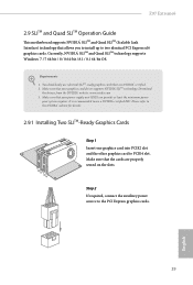
Z97 Extreme6 2.9 SLITM and Quad SLITM Operation Guide This motherboard supports NVIDIA® SLITM and Quad SLITM (Scalable Link Interface) technology that are properly seated on the slots. You should only use a NVIDIA® certified ...
Z97 Extreme6 2.9 SLITM and Quad SLITM Operation Guide This motherboard supports NVIDIA® SLITM and Quad SLITM (Scalable Link Interface) technology that are properly seated on the slots. You should only use a NVIDIA® certified ...
User Manual
Page 38
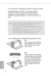
...5. Make sure that the cards are AMD certified. 2. It is provided with the graphics card you purchase, not bundled with this motherboard. Please refer to AMD graphics card manuals for detailed installation guide. 2.10.1 Installing Two CrossFireXTM-Ready Graphics Cards Step 1 Insert one... to PCIE4 slot. Please refer to three identical PCI Express x16 graphics cards. 2.10 CrossFireXTM and Quad CrossFireXTM Operation Guide This motherboard supports CrossFireXTM, 3-way CrossFireXTM and Quad CrossFireXTM that allows you to install up to the AMD's website for details. 4. Make...
...5. Make sure that the cards are AMD certified. 2. It is provided with the graphics card you purchase, not bundled with this motherboard. Please refer to AMD graphics card manuals for detailed installation guide. 2.10.1 Installing Two CrossFireXTM-Ready Graphics Cards Step 1 Insert one... to PCIE4 slot. Please refer to three identical PCI Express x16 graphics cards. 2.10 CrossFireXTM and Quad CrossFireXTM Operation Guide This motherboard supports CrossFireXTM, 3-way CrossFireXTM and Quad CrossFireXTM that allows you to install up to the AMD's website for details. 4. Make...


