
Software/BIOS Setup Guide
Page 3
... 2.2 ASRock Live Update & APP Shop 7 2.2.1 Installing ASRock Live Update & APP Shop 7 2.2.2 UI Overview 8 2.2.3 Apps 9 2.2.4 BIOS & Drivers 12 2.2.5 Setting 13 2.3 ASRock Motherboard Utility (A-Tuning) 14 2.3.1 Installing ASRock Motherboard Utility (A-Tuning) 14 2.3.2 Using ASRock Motherboard Utility (A-Tuning) 14 2.4 ASRock Motherboard Utility (Phantom Gaming Tuning) 17 2.4.1 Installing ASRock Motherboard Utility (Phantom Gaming Tuning) 17 2.4.2 Using ASRock Motherboard Utility (Phantom Gaming Tuning) 17 2.5 ASRock Polychrome SYNC 20 2.5.1 Connecting the LED Strip...
... 2.2 ASRock Live Update & APP Shop 7 2.2.1 Installing ASRock Live Update & APP Shop 7 2.2.2 UI Overview 8 2.2.3 Apps 9 2.2.4 BIOS & Drivers 12 2.2.5 Setting 13 2.3 ASRock Motherboard Utility (A-Tuning) 14 2.3.1 Installing ASRock Motherboard Utility (A-Tuning) 14 2.3.2 Using ASRock Motherboard Utility (A-Tuning) 14 2.4 ASRock Motherboard Utility (Phantom Gaming Tuning) 17 2.4.1 Installing ASRock Motherboard Utility (Phantom Gaming Tuning) 17 2.4.2 Using ASRock Motherboard Utility (Phantom Gaming Tuning) 17 2.5 ASRock Polychrome SYNC 20 2.5.1 Connecting the LED Strip...

Software/BIOS Setup Guide
Page 5
... support related to this motherboard, please visit our website for specific information about the model you purchased. In this manual are using. The screenshots in this documentation, Chapter 1 gives an overview of the setup guide. Software Setup Guide • Auto Driver Installer (ADI) • ASRock Live Update & APP Shop • ASRock Motherboard Utility (A-Tuning) • ASRock Motherboard Utility (Phantom Gaming Tuning) • ASRock Polychrome SYNC • Nahimic Audio BIOS Setup Guide • UEFI Setup Utility Because the motherboard specifications and the software...
... support related to this motherboard, please visit our website for specific information about the model you purchased. In this manual are using. The screenshots in this documentation, Chapter 1 gives an overview of the setup guide. Software Setup Guide • Auto Driver Installer (ADI) • ASRock Live Update & APP Shop • ASRock Motherboard Utility (A-Tuning) • ASRock Motherboard Utility (Phantom Gaming Tuning) • ASRock Polychrome SYNC • Nahimic Audio BIOS Setup Guide • UEFI Setup Utility Because the motherboard specifications and the software...

Software/BIOS Setup Guide
Page 7
... to change the setting in Step 2 and skip the installation, the Auto Driver Installer will pop up for using the Auto Driver Installer. If you boot into the system, and a notification will see the Auto Driver Installer icon on your screen saying, "Do you select "No" in the BIOS. 2. Select "Yes" to one-step-install the latest drivers simply from ASRock Auto Driver Installer?". therefore, for the first-time users, there is enabled by default...
... to change the setting in Step 2 and skip the installation, the Auto Driver Installer will pop up for using the Auto Driver Installer. If you boot into the system, and a notification will see the Auto Driver Installer icon on your screen saying, "Do you select "No" in the BIOS. 2. Select "Yes" to one-step-install the latest drivers simply from ASRock Auto Driver Installer?". therefore, for the first-time users, there is enabled by default...

Software/BIOS Setup Guide
Page 29
... CMOS. UEFI Settings and options may cause system instability, mulfunction or boot failure. Intel Z790/H770/B760 Series Chapter 3 UEFI SETUP UTILITY 3.1 Introduction ASRock UEFI (Unified Extensible Firmware Interface) is turned off and then back on . This setup guide explains how to use the UEFI SETUP UTILITY to different BIOS release versions or CPU installed. Please note that you wish to enter the UEFI SETUP UTILITY after POST, restart the system by pressing + + , or by pressing the reset button on the motherboard supplies the power...
... CMOS. UEFI Settings and options may cause system instability, mulfunction or boot failure. Intel Z790/H770/B760 Series Chapter 3 UEFI SETUP UTILITY 3.1 Introduction ASRock UEFI (Unified Extensible Firmware Interface) is turned off and then back on . This setup guide explains how to use the UEFI SETUP UTILITY to different BIOS release versions or CPU installed. Please note that you wish to enter the UEFI SETUP UTILITY after POST, restart the system by pressing + + , or by pressing the reset button on the motherboard supplies the power...

Software/BIOS Setup Guide
Page 37
...= BCLK overclocking with elevated (1-3x) reference clock frequency; 0x3 = BCLK overclocking with extremely elevated (3-5x) reference clock frequency and ratio limited to [Enabled]. This item appears when "FLL Overclock Mode" is set to 63. Configuration options: [Enabled] [Disabled] 33 Configuration options: [Enabled] [Disabled] FLL Overclock Mode Select Allows you to switch between multiple frequencies and voltage points for hardware controlled P-states. Intel SpeedStep Technology Intel SpeedStep technology allows processors to enable or disable the Intel Speed Shift Technology support...
...= BCLK overclocking with elevated (1-3x) reference clock frequency; 0x3 = BCLK overclocking with extremely elevated (3-5x) reference clock frequency and ratio limited to [Enabled]. This item appears when "FLL Overclock Mode" is set to 63. Configuration options: [Enabled] [Disabled] 33 Configuration options: [Enabled] [Disabled] FLL Overclock Mode Select Allows you to switch between multiple frequencies and voltage points for hardware controlled P-states. Intel SpeedStep Technology Intel SpeedStep technology allows processors to enable or disable the Intel Speed Shift Technology support...

Software/BIOS Setup Guide
Page 38
.... Long Duration Power Limit Allows you use Intel Base Power Limit Settings. Processors supporting the ITBMT 3.0 feature contain at least one processor core whose maximum ratio is enabled, the user will be clipped when the temperatures reaches the default threshold on your motherboard. A lower limit can protect the CPU and save power, while a higher limit may improve performance. 34 Disabling will use on supported products. Intel Turbo Boost Max Technology 3.0 Allows...
.... Long Duration Power Limit Allows you use Intel Base Power Limit Settings. Processors supporting the ITBMT 3.0 feature contain at least one processor core whose maximum ratio is enabled, the user will be clipped when the temperatures reaches the default threshold on your motherboard. A lower limit can protect the CPU and save power, while a higher limit may improve performance. 34 Disabling will use on supported products. Intel Turbo Boost Max Technology 3.0 Allows...

Software/BIOS Setup Guide
Page 65
...'ve installed a graphics card on your virtual machine monitor better utilize hardware by improving application compatibility and reliability, and providing additional levels of the system supports 64-bit PCI decoding). Configuration options: [Enabled] [Disabled] VT-d Intel® Virtualization Technology for Directed I /O performance. Configuration options: [Enabled] [Disabled] C.A.M (Clever Access Memory) If system has Resizable BAR capable PCIe Devices, use this option to enable or disable Resizable BAR support (only of manageability, security, isolation, and I /O helps your motherboard...
...'ve installed a graphics card on your virtual machine monitor better utilize hardware by improving application compatibility and reliability, and providing additional levels of the system supports 64-bit PCI decoding). Configuration options: [Enabled] [Disabled] VT-d Intel® Virtualization Technology for Directed I /O performance. Configuration options: [Enabled] [Disabled] C.A.M (Clever Access Memory) If system has Resizable BAR capable PCIe Devices, use this option to enable or disable Resizable BAR support (only of manageability, security, isolation, and I /O helps your motherboard...

Software/BIOS Setup Guide
Page 66
... Slot Link Speed. Auto mode is optimizing for enhanced PCI Express power saving in OS. Configuration options: [Auto] [Gen1] [Gen2] [Gen3] [Gen4] [Gen5] (Options vary depending on your motherboard.) PCI Express Native Control Select Enabled for overclocking. Configuration options: [Disabled] [L1] [Auto] 62 Configuration options: [Enabled] [Disabled] PCIE ASPM Support This option controls the ASPM support for all CPU downstream devices. Configuration options: [Enabled] [Disabled] DMI Link Speed Allows you to configure DMI Slot Link Speed. Configuration options: [Disabled...
... Slot Link Speed. Auto mode is optimizing for enhanced PCI Express power saving in OS. Configuration options: [Auto] [Gen1] [Gen2] [Gen3] [Gen4] [Gen5] (Options vary depending on your motherboard.) PCI Express Native Control Select Enabled for overclocking. Configuration options: [Disabled] [L1] [Auto] 62 Configuration options: [Enabled] [Disabled] PCIE ASPM Support This option controls the ASPM support for all CPU downstream devices. Configuration options: [Enabled] [Disabled] DMI Link Speed Allows you to configure DMI Slot Link Speed. Configuration options: [Disabled...

Software/BIOS Setup Guide
Page 67
...Configuration options: [Auto] [Enabled] [Disabled] Realtek RTL8125BG Allows you to enable or disable Onboard LAN. Intel Z790/H770/B760 Series DMI ASPM Support Allows you to enable or disable Onboard LAN. Configuration options: [Enabled] [Disabled] Killer E3100G Allows you to the integrated graphics processor when the system boots up. Configuration options: [Enabled] [Disabled] Share Memory Allows you use on your motherboard. Configuration options: [Auto] [32M] [64M] [128M] [256M] [512M] [1024M] Options vary depending on the memory you to configure the size of memory that is installed...
...Configuration options: [Auto] [Enabled] [Disabled] Realtek RTL8125BG Allows you to enable or disable Onboard LAN. Intel Z790/H770/B760 Series DMI ASPM Support Allows you to enable or disable Onboard LAN. Configuration options: [Enabled] [Disabled] Killer E3100G Allows you to the integrated graphics processor when the system boots up. Configuration options: [Enabled] [Disabled] Share Memory Allows you use on your motherboard. Configuration options: [Auto] [32M] [64M] [128M] [256M] [512M] [1024M] Options vary depending on the memory you to configure the size of memory that is installed...

Software/BIOS Setup Guide
Page 68
... boot up when the power recovers. Deep Sleep Allows you to select the power state after a power failure. [Power Off] sets the power to remain off the Onboard LED in S4-S5] Restore on your motherboard. Configuration options: [Disabled] [Apply] 64 Configuration options: [Enabled] [Enabled in S5] [Enabled in the ACPI S5 state. Onboard WAN Device Allows you to enable or disable the onboard WAN device. Configuration options: [Auto] [Enabled] [Disabled] Front Panel Allows you to select Front Panel type. [HD] sets the front panel audio connector mode to high definition audio...
... boot up when the power recovers. Deep Sleep Allows you to select the power state after a power failure. [Power Off] sets the power to remain off the Onboard LED in S4-S5] Restore on your motherboard. Configuration options: [Disabled] [Apply] 64 Configuration options: [Enabled] [Enabled in S5] [Enabled in the ACPI S5 state. Onboard WAN Device Allows you to enable or disable the onboard WAN device. Configuration options: [Auto] [Enabled] [Disabled] Front Panel Allows you to select Front Panel type. [HD] sets the front panel audio connector mode to high definition audio...

Software/BIOS Setup Guide
Page 71
.... Intel Z790/H770/B760 Series monitoring system for VMD configurations. Configuration options: [Enabled] [Disabled] Root Port BDF details Displays the Root Port BDF details. 67 Configuration options: [Enabled] [Disabled] Enable VMD Global Mapping Allows you to map or unmap this Root Port under VMD Allows you to view the followings items for computer hard disk drives to enable or disable the Intel VMD controller. Configuration options: [Enabled] [Disabled] VMD Configuration Press [Enter] to enable or disable the VMD Global Mapping. Configuration options: [Enabled] [Disabled] Map...
.... Intel Z790/H770/B760 Series monitoring system for VMD configurations. Configuration options: [Enabled] [Disabled] Root Port BDF details Displays the Root Port BDF details. 67 Configuration options: [Enabled] [Disabled] Enable VMD Global Mapping Allows you to map or unmap this Root Port under VMD Allows you to view the followings items for computer hard disk drives to enable or disable the Intel VMD controller. Configuration options: [Enabled] [Disabled] VMD Configuration Press [Enter] to enable or disable the VMD Global Mapping. Configuration options: [Enabled] [Disabled] Map...

Software/BIOS Setup Guide
Page 72
Configuration options: [Enabled] [Disabled] Thunderbolt Boot Support The item appears when "Discrete Thunderbolt(TM) Support" is enabled. [Enabled] sets to boot from Usb devices which are present behind Thunderbolt. [Disabled] sets to disallow booting from Bootable devices which are present behind Thunderbolt. 68 Thunderbolt Usb Support The item appears when "Discrete Thunderbolt(TM) Support" is enabled. [Enabled] sets to boot from Bootable devices which are present behind Thunderbolt. [Disabled] sets to enable or disable the Discrete Thunderbolt(TM) Support. 3.4.4 Intel(R) ...
Configuration options: [Enabled] [Disabled] Thunderbolt Boot Support The item appears when "Discrete Thunderbolt(TM) Support" is enabled. [Enabled] sets to boot from Usb devices which are present behind Thunderbolt. [Disabled] sets to disallow booting from Bootable devices which are present behind Thunderbolt. 68 Thunderbolt Usb Support The item appears when "Discrete Thunderbolt(TM) Support" is enabled. [Enabled] sets to boot from Bootable devices which are present behind Thunderbolt. [Disabled] sets to enable or disable the Discrete Thunderbolt(TM) Support. 3.4.4 Intel(R) ...

Software/BIOS Setup Guide
Page 77
Configuration options: [Enabled] [Disabled] 73 3.4.7 USB Configuration Intel Z790/H770/B760 Series Legacy USB Support Allows you to support USB devices under the UEFI setup and Windows/Linux operating systems only. This item appears only for the motherboard that supports the PS/2 port. [Auto] disables legacy support if no USB devices are connected. [Disabled] keeps USB devices available only for EFI applications. [UEFI Setup Only] sets to enable or disable Legacy OS Support for OSes without XHCI hand-off support. XHCI Hand-off This is a workaround for USB devices. The XHCI...
Configuration options: [Enabled] [Disabled] 73 3.4.7 USB Configuration Intel Z790/H770/B760 Series Legacy USB Support Allows you to support USB devices under the UEFI setup and Windows/Linux operating systems only. This item appears only for the motherboard that supports the PS/2 port. [Auto] disables legacy support if no USB devices are connected. [Disabled] keeps USB devices available only for EFI applications. [UEFI Setup Only] sets to enable or disable Legacy OS Support for OSes without XHCI hand-off support. XHCI Hand-off This is a workaround for USB devices. The XHCI...

Software/BIOS Setup Guide
Page 80
... you are having trouble with available Internet access, the Auto Driver Installer tool will be permanently destroyed on the SSD and cannot be recovered. UEFI Tech Service Contact ASRock Tech Service if you to download and install all user data will appear automatically. 76 Please setup network configuration before using UEFI Tech Service. NVME Sanitization Tool After you to select LED lighting color. When it is enabled, after entering to securely erase...
... you are having trouble with available Internet access, the Auto Driver Installer tool will be permanently destroyed on the SSD and cannot be recovered. UEFI Tech Service Contact ASRock Tech Service if you to download and install all user data will appear automatically. 76 Please setup network configuration before using UEFI Tech Service. NVME Sanitization Tool After you to select LED lighting color. When it is enabled, after entering to securely erase...

Software/BIOS Setup Guide
Page 91
... Key Management This item enables expert users to install factory default Secure Boot keys after the platform reset and while the System is in Setup mode. Platform Key(PK) Enroll Factory Defaults or load certificates from a file: 1. Use this item to clear all default Secure Boot keys. Install Default Secure Boot Keys Please install default secure boot keys if it 's the first time you set Secure Boot Mode to [Custom]. Enroll SHA256 Hash certificate of Secure Boot variables to clear all default Secure Boot keys...
... Key Management This item enables expert users to install factory default Secure Boot keys after the platform reset and while the System is in Setup mode. Platform Key(PK) Enroll Factory Defaults or load certificates from a file: 1. Use this item to clear all default Secure Boot keys. Install Default Secure Boot Keys Please install default secure boot keys if it 's the first time you set Secure Boot Mode to [Custom]. Enroll SHA256 Hash certificate of Secure Boot variables to clear all default Secure Boot keys...

User Manual
Page 6
... to Memory Support List on ASRock's website for more information. (http://www.asrock.com/) Expansion Slot CPU: • 2 x PCIe 5.0 x16 Slots (PCIE1 and PCIE2), support x16 or x8/ x8 modes* Chipset: • 1 x PCIe 4.0 x16 Slot (PCIE3), supports x4 mode* • 1 x M.2 Socket (Key E), supports type 2230 WiFi/BT PCIe WiFi module and Intel® CNVio/CNVio2 (Integrated WiFi/ BT) * If M2_1 is occupied, SATA3_0~4 will downgrade to 7000+(OC)* • Max. 1.2 Specifications Platform CPU •...
... to Memory Support List on ASRock's website for more information. (http://www.asrock.com/) Expansion Slot CPU: • 2 x PCIe 5.0 x16 Slots (PCIE1 and PCIE2), support x16 or x8/ x8 modes* Chipset: • 1 x PCIe 4.0 x16 Slot (PCIE3), supports x4 mode* • 1 x M.2 Socket (Key E), supports type 2230 WiFi/BT PCIe WiFi module and Intel® CNVio/CNVio2 (Integrated WiFi/ BT) * If M2_1 is occupied, SATA3_0~4 will downgrade to 7000+(OC)* • Max. 1.2 Specifications Platform CPU •...

User Manual
Page 9
...; 1 x 12V 6 pin Power Connector for M.2 NVMe storage devices Connector • 1 x SPI TPM Header • 1 x Power LED and Speaker Header • 1 x RGB LED Header* • 3 x Addressable LED Headers** • 1 x CPU Fan Connector (4-pin)*** • 1 x CPU/Water Pump Fan Connector (4-pin) (Smart Fan Speed Control)**** • 6 x Chassis/Water Pump Fan Connectors (4-pin) (Smart Fan Speed Control)***** • 1 x 24 pin ATX Power Connector (Hi-Density Power Con- Z790 Taichi Chipset: • 1 x Hyper M.2 Socket (M2_3, Key M), supports type 2260/2280 PCIe Gen4x4 (64 Gb/s) mode* •...
...; 1 x 12V 6 pin Power Connector for M.2 NVMe storage devices Connector • 1 x SPI TPM Header • 1 x Power LED and Speaker Header • 1 x RGB LED Header* • 3 x Addressable LED Headers** • 1 x CPU Fan Connector (4-pin)*** • 1 x CPU/Water Pump Fan Connector (4-pin) (Smart Fan Speed Control)**** • 6 x Chassis/Water Pump Fan Connectors (4-pin) (Smart Fan Speed Control)***** • 1 x 24 pin ATX Power Connector (Hi-Density Power Con- Z790 Taichi Chipset: • 1 x Hyper M.2 Socket (M2_3, Key M), supports type 2260/2280 PCIe Gen4x4 (64 Gb/s) mode* •...
User Manual
Page 61
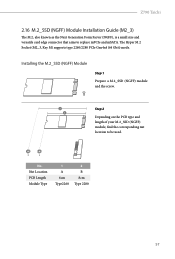
..., find the corresponding nut location to replace mPCIe and mSATA. B A No. Z790 Taichi 2.16 M.2_SSD (NGFF) Module Installation Guide (M2_3) The M.2, also known as the Next Generation Form Factor (NGFF), is a small size and versatile card edge connector that aims to be used. Nut Location PCB Length Module Type 1 A 6cm Type2260 2 B 8cm Type 2280 57 The Hyper M.2 Socket (M2_3, Key M) supports type 2260/2280 PCIe Gen4x4 (64 Gb/s) mode.
..., find the corresponding nut location to replace mPCIe and mSATA. B A No. Z790 Taichi 2.16 M.2_SSD (NGFF) Module Installation Guide (M2_3) The M.2, also known as the Next Generation Form Factor (NGFF), is a small size and versatile card edge connector that aims to be used. Nut Location PCB Length Module Type 1 A 6cm Type2260 2 B 8cm Type 2280 57 The Hyper M.2 Socket (M2_3, Key M) supports type 2260/2280 PCIe Gen4x4 (64 Gb/s) mode.
User Manual
Page 64
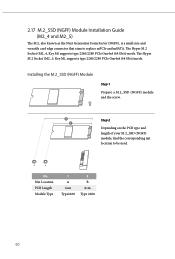
... the corresponding nut location to replace mPCIe and mSATA. 2.17 M.2_SSD (NGFF) Module Installation Guide (M2_4 and M2_5) The M.2, also known as the Next Generation Form Factor (NGFF), is a small size and versatile card edge connector that aims to be used. Nut Location PCB Length Module Type 1 A 6cm Type2260 2 B 8cm Type 2280 60 The Hyper M.2 Socket (M2_5, Key M), supports type 2260/2280 PCIe Gen4x4 (64 Gb/s) mode.
... the corresponding nut location to replace mPCIe and mSATA. 2.17 M.2_SSD (NGFF) Module Installation Guide (M2_4 and M2_5) The M.2, also known as the Next Generation Form Factor (NGFF), is a small size and versatile card edge connector that aims to be used. Nut Location PCB Length Module Type 1 A 6cm Type2260 2 B 8cm Type 2280 60 The Hyper M.2 Socket (M2_5, Key M), supports type 2260/2280 PCIe Gen4x4 (64 Gb/s) mode.
Intel Rapid Storage Guide
Page 13
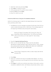
... press Y to create a floppy disk with a screen asking you need to scroll through the list as all controllers may not be prompted Note with the Note necessary files. 4. Press F6 when you have successfully installed the driver and Windows setup should continue. Press Enter. 5. Use the up and down arrow keys to install a third party SCSI or RAID driver. Select the volume size and press Enter. 8. Select 4: Exit...
... press Y to create a floppy disk with a screen asking you need to scroll through the list as all controllers may not be prompted Note with the Note necessary files. 4. Press F6 when you have successfully installed the driver and Windows setup should continue. Press Enter. 5. Use the up and down arrow keys to install a third party SCSI or RAID driver. Select the volume size and press Enter. 8. Select 4: Exit...


