
User Manual
Page 5
...1.1 Package Contents 1 1.2 Specifications 2 1.3 Motherboard Layout 7 1.4 I/O Panel 9 Chapter 2 Installation 10 2.1 Installing the CPU 11 2.2 Installing the CPU Fan and Heatsink 14 2.3 Installing Memory Modules (DIMM) 15 2.4 Expansion Slots (PCI Express Slots) 17 2.5 Jumpers Setup 19 2.6 Onboard Headers and Connectors 20 2.7 Post Status Checker 26 2.8 CrossFireXTM and Quad CrossFireXTM Operation Guide 27 2.8.1 Installing Two CrossFireXTM-Ready Graphics Cards 27 2.8.2 Driver Installation and Setup 29 2.9 M.2_SSD (NGFF) Module Installation Guide (M2_1 and M2_2) 30...
...1.1 Package Contents 1 1.2 Specifications 2 1.3 Motherboard Layout 7 1.4 I/O Panel 9 Chapter 2 Installation 10 2.1 Installing the CPU 11 2.2 Installing the CPU Fan and Heatsink 14 2.3 Installing Memory Modules (DIMM) 15 2.4 Expansion Slots (PCI Express Slots) 17 2.5 Jumpers Setup 19 2.6 Onboard Headers and Connectors 20 2.7 Post Status Checker 26 2.8 CrossFireXTM and Quad CrossFireXTM Operation Guide 27 2.8.1 Installing Two CrossFireXTM-Ready Graphics Cards 27 2.8.2 Driver Installation and Setup 29 2.9 M.2_SSD (NGFF) Module Installation Guide (M2_1 and M2_2) 30...

User Manual
Page 8
... guide of the BIOS setup. In this motherboard, please visit our website for specific information about the model you for M.2 Socket (Optional) • 1 x I/O Panel Shield 1 English Chapter 4 contains the configuration guide of the software and utilities. Because the motherboard specifications and the BIOS software might be updated, the content of this documentation occur, the updated version will be available on ASRock's website as well. You may find the latest VGA cards and CPU support list on ASRock...
... guide of the BIOS setup. In this motherboard, please visit our website for specific information about the model you for M.2 Socket (Optional) • 1 x I/O Panel Shield 1 English Chapter 4 contains the configuration guide of the software and utilities. Because the motherboard specifications and the BIOS software might be updated, the content of this documentation occur, the updated version will be available on ASRock's website as well. You may find the latest VGA cards and CPU support list on ASRock...

User Manual
Page 11
... LAN Port with LED (ACT/LINK LED and SPEED LED) • HD Audio Jacks: Line in / Front Speaker / Microphone Storage • 4 x SATA3 6.0 Gb/s Connectors, support RAID (RAID 0, RAID 1, RAID 5, RAID 10, Intel Rapid Storage Technology 18), NCQ, AHCI and Hot Plug* * If M2_1 is occupied by a SATA-type M.2 device, SATA3_3 will be disabled. • 1 x Hyper M.2 Socket (M2_1), supports M Key type 2260/2280 M.2 SATA3 6.0 Gb/s module and M.2 PCI Express module up to Gen4x4 (64 Gb/s) (with 11th Gen Intel® Core™ Processors...
... LAN Port with LED (ACT/LINK LED and SPEED LED) • HD Audio Jacks: Line in / Front Speaker / Microphone Storage • 4 x SATA3 6.0 Gb/s Connectors, support RAID (RAID 0, RAID 1, RAID 5, RAID 10, Intel Rapid Storage Technology 18), NCQ, AHCI and Hot Plug* * If M2_1 is occupied by a SATA-type M.2 device, SATA3_3 will be disabled. • 1 x Hyper M.2 Socket (M2_1), supports M Key type 2260/2280 M.2 SATA3 6.0 Gb/s module and M.2 PCI Express module up to Gen4x4 (64 Gb/s) (with 11th Gen Intel® Core™ Processors...

User Manual
Page 12
...) (Smart Fan Speed Control) * The Chassis/Water Pump Fan supports the water cooler fan of maximum 2A (24W) fan power. * CPU_FAN2/WP, CHA_FAN1/WP, CHA_FAN2/WP, CHA_ FAN3/WP and CHA_FAN4/WP can auto detect if 3-pin or 4-pin fan is in use. • 1 x 24 pin ATX Power Connector • 1 x 8 pin 12V Power Connector (Hi-Density Power Connector) • 1 x 4 pin 12V Power Connector (Hi-Density Power Connector) • 1 x Front Panel Audio Connector • 1 x Thunderbolt AIC Connector (5-pin) (Supports ASRock Thunderbolt 4 AIC Card) • 2 x USB 2.0 Headers (Support 4 USB 2.0 ports) (Supports...
...) (Smart Fan Speed Control) * The Chassis/Water Pump Fan supports the water cooler fan of maximum 2A (24W) fan power. * CPU_FAN2/WP, CHA_FAN1/WP, CHA_FAN2/WP, CHA_ FAN3/WP and CHA_FAN4/WP can auto detect if 3-pin or 4-pin fan is in use. • 1 x 24 pin ATX Power Connector • 1 x 8 pin 12V Power Connector (Hi-Density Power Connector) • 1 x 4 pin 12V Power Connector (Hi-Density Power Connector) • 1 x Front Panel Audio Connector • 1 x Thunderbolt AIC Connector (5-pin) (Supports ASRock Thunderbolt 4 AIC Card) • 2 x USB 2.0 Headers (Support 4 USB 2.0 ports) (Supports...

User Manual
Page 13
... UEFI Legal BIOS with overclocking, including adjusting the setting in the BIOS, applying Untied Overclocking Technology, or using third-party overclocking tools. We are not responsible for possible damage caused by CPU temperature): CPU, CPU/Water Pump, Chassis/Water Pump Fans • Fan Multi-Speed Control: CPU, CPU/Water Pump, Chassis/ Water Pump Fans • CASE OPEN detection • Voltage monitoring: +12V, +5V, +3.3V, CPU Vcore, DRAM, VPPM, VCCIN_AUX, VCCSA, VCCIO, VCCPLL, ATX+5VSB • Microsoft® Windows®...
... UEFI Legal BIOS with overclocking, including adjusting the setting in the BIOS, applying Untied Overclocking Technology, or using third-party overclocking tools. We are not responsible for possible damage caused by CPU temperature): CPU, CPU/Water Pump, Chassis/Water Pump Fans • Fan Multi-Speed Control: CPU, CPU/Water Pump, Chassis/ Water Pump Fans • CASE OPEN detection • Voltage monitoring: +12V, +5V, +3.3V, CPU Vcore, DRAM, VPPM, VCCIN_AUX, VCCSA, VCCIO, VCCPLL, ATX+5VSB • Microsoft® Windows®...

User Manual
Page 15
...) 7 RGB LED Header (RGB_LED2) 8 Addressable LED Header (ADDR_LED1) 9 ATX Power Connector (ATXPWR1) 10 Chassis/Water Pump Fan Connector (CHA_FAN2/WP) 11 Front Panel Type C USB 3.2 Gen1 Header (USB3_TC_1) 12 SATA3 Connector (SATA3_0) 13 SATA3 Connector (SATA3_1) 14 USB 3.2 Gen1 Header (USB3_5_6) 15 SATA3 Connector (SATA3_2)(Upper) 16 SATA3 Connector (SATA3_3)(Lower) 17 System Panel Header (PANEL1) 18 Clear CMOS Jumper (CLRMOS1) 19 USB 2.0 Header (USB5_6) 20 USB 2.0 Header (USB3_4) 21 SPI TPM Header (SPI_TPM_J1) 22 Chassis Intrusion and Speaker Header (SPK_CI1) 23 Post Status...
...) 7 RGB LED Header (RGB_LED2) 8 Addressable LED Header (ADDR_LED1) 9 ATX Power Connector (ATXPWR1) 10 Chassis/Water Pump Fan Connector (CHA_FAN2/WP) 11 Front Panel Type C USB 3.2 Gen1 Header (USB3_TC_1) 12 SATA3 Connector (SATA3_0) 13 SATA3 Connector (SATA3_1) 14 USB 3.2 Gen1 Header (USB3_5_6) 15 SATA3 Connector (SATA3_2)(Upper) 16 SATA3 Connector (SATA3_3)(Lower) 17 System Panel Header (PANEL1) 18 Clear CMOS Jumper (CLRMOS1) 19 USB 2.0 Header (USB5_6) 20 USB 2.0 Header (USB3_4) 21 SPI TPM Header (SPI_TPM_J1) 22 Chassis Intrusion and Speaker Header (SPK_CI1) 23 Post Status...

User Manual
Page 24
... settings for PCI Express x1 lane width cards. Please read the documentation of the expansion card and make sure that the power supply is switched off or the power cord is used for the card before you start the installation. PCIE3 (PCIe 3.0 x1 slot) is unplugged. PCIE4 (PCIe 3.0 x16 slot) is used for PCI Express x1 lane width cards. PCIE2 (PCIe 3.0 x1 slot) is used for PCI Express x4 lane width graphics cards. 17 English PCIE4 (PCIe 3.0 x16 slot) is used...
... settings for PCI Express x1 lane width cards. Please read the documentation of the expansion card and make sure that the power supply is switched off or the power cord is used for the card before you start the installation. PCIE3 (PCIe 3.0 x1 slot) is unplugged. PCIE4 (PCIe 3.0 x16 slot) is used for PCI Express x1 lane width cards. PCIE2 (PCIe 3.0 x1 slot) is used for PCI Express x4 lane width graphics cards. 17 English PCIE4 (PCIe 3.0 x16 slot) is used...

User Manual
Page 26
... the power supply. If you do not clear the CMOS right after clearing the CMOS. Please be noted that the password, date, time, and user default profile will be detected. If no jumper cap is placed on the pins, the jumper is removed. Please adjust the BIOS option "Clear Status" to short the pins on the pins, the jumper is "Short". To clear and reset the system parameters to clear the data in CMOS. Z590M Pro4 2.5 Jumpers Setup The...
... the power supply. If you do not clear the CMOS right after clearing the CMOS. Please be noted that the password, date, time, and user default profile will be detected. If no jumper cap is placed on the pins, the jumper is removed. Please adjust the BIOS option "Clear Status" to short the pins on the pins, the jumper is "Short". To clear and reset the system parameters to clear the data in CMOS. Z590M Pro4 2.5 Jumpers Setup The...

User Manual
Page 27
... pins before connecting the cables. HDLED (Hard Drive Activity LED): Connect to the power status indicator on the chassis to this header according to the motherboard. English Chassis Intrusion and Speaker Header (7-pin SPK_CI1) (see p.7, No. 17) PLED+ PLEDPWRBTN# GND 1 GND RESET# GND HDLEDHDLED+ Connect the power switch, reset switch and system status indicator on the chassis front panel. 2.6 Onboard Headers and Connectors Onboard headers and connectors are matched correctly. A front panel module mainly consists of power switch, reset switch, power LED, hard drive activity LED...
... pins before connecting the cables. HDLED (Hard Drive Activity LED): Connect to the power status indicator on the chassis to this header according to the motherboard. English Chassis Intrusion and Speaker Header (7-pin SPK_CI1) (see p.7, No. 17) PLED+ PLEDPWRBTN# GND 1 GND RESET# GND HDLEDHDLED+ Connect the power switch, reset switch and system status indicator on the chassis front panel. 2.6 Onboard Headers and Connectors Onboard headers and connectors are matched correctly. A front panel module mainly consists of power switch, reset switch, power LED, hard drive activity LED...

User Manual
Page 31
... Connector (5-pin TB1) (see p.7, No. 26) 8 5 This motherboard provides a 8-pin ATX 12V 4 1 power connector. For advanced overclocking, we suggest using this connector together with ATX12V1. 1 Please connect a Thunderbolt™ add-in only one orientation. *Connecting an ATX 12V 4-pin cable to this connector. Please connect an ATX 12V power supply to this connector. *The power supply plug fits into this connector in card (AIC) to ATX12V2 is for the CPU and not the graphics card. To use a 4-pin ATX power supply, please plug it along Pin...
... Connector (5-pin TB1) (see p.7, No. 26) 8 5 This motherboard provides a 8-pin ATX 12V 4 1 power connector. For advanced overclocking, we suggest using this connector together with ATX12V1. 1 Please connect a Thunderbolt™ add-in only one orientation. *Connecting an ATX 12V 4-pin cable to this connector. Please connect an ATX 12V power supply to this connector. *The power supply plug fits into this connector in card (AIC) to ATX12V2 is for the CPU and not the graphics card. To use a 4-pin ATX power supply, please plug it along Pin...

User Manual
Page 34
Z590M Pro4 2.8 CrossFireXTM and Quad CrossFireXTM Operation Guide This motherboard supports CrossFireXTM and Quad CrossFireXTM that the cards are AMD certified. 2. Download the drivers from the AMD's website: www.amd.com 3. Please refer to enable CrossFireXTM. Make sure that allows you to install up to your graphics card driver supports AMD CrossFireXTM technology. Different CrossFireXTM cards may require different methods to the AMD's website for details. 4. Please refer to three identical PCI Express x16...
Z590M Pro4 2.8 CrossFireXTM and Quad CrossFireXTM Operation Guide This motherboard supports CrossFireXTM and Quad CrossFireXTM that the cards are AMD certified. 2. Download the drivers from the AMD's website: www.amd.com 3. Please refer to enable CrossFireXTM. Make sure that allows you to install up to your graphics card driver supports AMD CrossFireXTM technology. Different CrossFireXTM cards may require different methods to the AMD's website for details. 4. Please refer to three identical PCI Express x16...

User Manual
Page 36
... 2 Remove the AMD drivers if you have any previously installed Catalyst drivers prior to your computer and boot into OS. The Catalyst Uninstaller is an optional download. Step 5 In the left pane, click Performance and then AMD CrossFireXTM. Select the GPU number according to installation. Step 3 Install the required drivers and CATALYST Control Center then restart your system. Z590M Pro4 2.8.2 Driver Installation and Setup Step 1 Power on your graphics card and...
... 2 Remove the AMD drivers if you have any previously installed Catalyst drivers prior to your computer and boot into OS. The Catalyst Uninstaller is an optional download. Step 5 In the left pane, click Performance and then AMD CrossFireXTM. Select the GPU number according to installation. Step 3 Install the required drivers and CATALYST Control Center then restart your system. Z590M Pro4 2.8.2 Driver Installation and Setup Step 1 Power on your graphics card and...

User Manual
Page 48
... installation wizard to install those required drivers. If the Main Menu does not appear automatically, locate and double click on the support CD driver page. Drivers Menu The drivers compatible to display the menu. The CD automatically displays the Main Menu if "AUTORUN" is enabled in the Support CD to your system will be auto-detected and listed on the file "ASRSETUP.EXE" in your CD-ROM drive. Running The Support CD To begin using the support...
... installation wizard to install those required drivers. If the Main Menu does not appear automatically, locate and double click on the support CD driver page. Drivers Menu The drivers compatible to display the menu. The CD automatically displays the Main Menu if "AUTORUN" is enabled in the Support CD to your system will be auto-detected and listed on the file "ASRSETUP.EXE" in your CD-ROM drive. Running The Support CD To begin using the support...

User Manual
Page 82
...-IOV Support If system has SR-IOV capable PCIe Devices, this option Enables or Disables Single Root IO Virtualization Support. VT-d Intel® Virtualization Technology for PCIE1. 75 English DMI Link Speed Configure DMI Slot Link Speed. Above 4G Decoding Enable or disable 64bit capable Devices to be decoded in Above 4G Address Space (only if the system supports 64 bit PCI decoding). 4.6.2 Chipset Configuration Z590M Pro4 Primary Graphics Adapter Select a primary VGA. Auto mode is optimizing for overclocking.
...-IOV Support If system has SR-IOV capable PCIe Devices, this option Enables or Disables Single Root IO Virtualization Support. VT-d Intel® Virtualization Technology for PCIE1. 75 English DMI Link Speed Configure DMI Slot Link Speed. Above 4G Decoding Enable or disable 64bit capable Devices to be decoded in Above 4G Address Space (only if the system supports 64 bit PCI decoding). 4.6.2 Chipset Configuration Z590M Pro4 Primary Graphics Adapter Select a primary VGA. Auto mode is optimizing for overclocking.

User Manual
Page 83
... graphics card is installed. 76 English PCIE ASPM Support This option enables/disables the ASPM support for all CPU downstream devices. IGPU Multi-Monitor Select disable to enable onboard HD audio and automatically disable it when a sound card is installed. Share Memory Configure the size of the DMI Link. Onboard HD Audio Enable/disable onboard HD audio. PCIE3 Link Speed Select the link speed for enhanced PCI Express power saving in OS. PCI Express Native Control Select Enable for PCIE3. Inte(R) Ethernet Connection I219-V Enable or disable the onboard network interface...
... graphics card is installed. 76 English PCIE ASPM Support This option enables/disables the ASPM support for all CPU downstream devices. IGPU Multi-Monitor Select disable to enable onboard HD audio and automatically disable it when a sound card is installed. Share Memory Configure the size of the DMI Link. Onboard HD Audio Enable/disable onboard HD audio. PCIE3 Link Speed Select the link speed for enhanced PCI Express power saving in OS. PCI Express Native Control Select Enable for PCIE3. Inte(R) Ethernet Connection I219-V Enable or disable the onboard network interface...

User Manual
Page 84
.... RGB LED This option enables/disables the RGB LED. 77 English WAN Radio Enable/disable the WiFi module's connectivity. Bluetooth Enable/disable the Bluetooth connectivity. Deep Sleep Configure deep sleep mode for the onboard digital outputs. Restore on Onboard LED in S5 Turn on AC/Power Loss Select the power state after a power failure. Restore Onboard LED Default Restore Onboard LED default value. Onboard WAN Device Use this item to boot up when the power recovers. Turn On Onboard LED in the ACPI S5 state. Onboard HDMI HD Audio Enable audio for power saving...
.... RGB LED This option enables/disables the RGB LED. 77 English WAN Radio Enable/disable the WiFi module's connectivity. Bluetooth Enable/disable the Bluetooth connectivity. Deep Sleep Configure deep sleep mode for the onboard digital outputs. Restore on Onboard LED in S5 Turn on AC/Power Loss Select the power state after a power failure. Restore Onboard LED Default Restore Onboard LED default value. Onboard WAN Device Use this item to boot up when the power recovers. Turn On Onboard LED in the ACPI S5 state. Onboard HDMI HD Audio Enable audio for power saving...

User Manual
Page 86
... support Specify Windows 10 Thunderbolt support level. Enabled: OS Native support only. Thunderbolt Boot Support Enabled to allow booting from Usb devices which are present behind Thunderbolt. no RTD3. 79 English Thunderbolt Usb Support Enabled to allow booting from Bootable devices which are present behind Thunderbolt. Titan Ridge Workaround for OSUP Enable or disable Titan Ridge Workaround for OSUP. Disabled: No OS native support. 4.6.4 Intel(R) Thunderbolt Z590M Pro4 Discrete Thunderbolt(TM) Support Enable or disable...
... support Specify Windows 10 Thunderbolt support level. Enabled: OS Native support only. Thunderbolt Boot Support Enabled to allow booting from Usb devices which are present behind Thunderbolt. no RTD3. 79 English Thunderbolt Usb Support Enabled to allow booting from Bootable devices which are present behind Thunderbolt. Titan Ridge Workaround for OSUP Enable or disable Titan Ridge Workaround for OSUP. Disabled: No OS native support. 4.6.4 Intel(R) Thunderbolt Z590M Pro4 Discrete Thunderbolt(TM) Support Enable or disable...

User Manual
Page 91
... drivers please change the SATA mode to your USB storage device. Please setup network configuration before using UEFI Tech Service. UEFI Tech Service Contact ASRock Tech Service if you to copy the RAID driver from the support CD to RAID, then you Sanitize SSD, all user data will be permanently destroyed on the SSD and cannot be recovered. Easy RAID Installer Easy RAID Installer helps you are having trouble with your UEFI. 84 English 4.7 Tools ASRock Polychrome RGB Select LED lighting...
... drivers please change the SATA mode to your USB storage device. Please setup network configuration before using UEFI Tech Service. UEFI Tech Service Contact ASRock Tech Service if you to copy the RAID driver from the support CD to RAID, then you Sanitize SSD, all user data will be permanently destroyed on the SSD and cannot be recovered. Easy RAID Installer Easy RAID Installer helps you are having trouble with your UEFI. 84 English 4.7 Tools ASRock Polychrome RGB Select LED lighting...
User Manual
Page 92
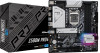
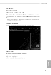
...), Auto ASRock Internet Flash downloads and updates the latest UEFI firmware version from our servers for Internet Flash. Internet Setting Enable or disable sound effects in your USB pen drive before using this to download the UEFI firmware. 85 English UEFI Download Server Select a server to configure internet connection settings for you. Internet Flash - Please setup network configuration before using Internet Flash. *For BIOS backup and recovery purpose, it is recommended to plug in the setup utility. Network Configuration Use this function. Z590M Pro4 Intel MEI Flash Starts...
...), Auto ASRock Internet Flash downloads and updates the latest UEFI firmware version from our servers for Internet Flash. Internet Setting Enable or disable sound effects in your USB pen drive before using this to download the UEFI firmware. 85 English UEFI Download Server Select a server to configure internet connection settings for you. Internet Flash - Please setup network configuration before using Internet Flash. *For BIOS backup and recovery purpose, it is recommended to plug in the setup utility. Network Configuration Use this function. Z590M Pro4 Intel MEI Flash Starts...

User Manual
Page 97
... settings in the UEFI Setup Utility. 4.9 Security Screen In this section you may also clear the user password. Intel(R) Platform Trust Technology Enable/disable Intel PTT in the UEFI Setup Utility. Leave it blank and press enter to remove the password. Users are unable to change the password for Secure Boot. Secure Boot Use this option to enable or disable support for the administrator account. Supervisor Password Set or change the settings in ME. Leave it blank and press enter to remove the password. Disable...
... settings in the UEFI Setup Utility. 4.9 Security Screen In this section you may also clear the user password. Intel(R) Platform Trust Technology Enable/disable Intel PTT in the UEFI Setup Utility. Leave it blank and press enter to remove the password. Users are unable to change the password for Secure Boot. Secure Boot Use this option to enable or disable support for the administrator account. Supervisor Password Set or change the settings in ME. Leave it blank and press enter to remove the password. Disable...


