User Manual
Page 12
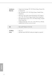
... Vcore, DRAM, VPPM, PCH, VCCSA, VCCST, VCCIO • Microsoft® Windows® 10 64-bit • FCC, CE • ErP/EuP ready (ErP/EuP ready power supply is required) English 6
... Vcore, DRAM, VPPM, PCH, VCCSA, VCCST, VCCIO • Microsoft® Windows® 10 64-bit • FCC, CE • ErP/EuP ready (ErP/EuP ready power supply is required) English 6
User Manual
Page 23
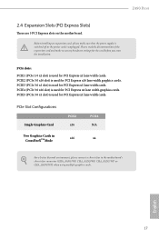
Please read the documentation of the expansion card and make sure that the power supply is switched off or the power cord is used for PCI Express x4 lane width graphics cards. PCIE4 (PCIe 3.0 x16 slot) is unplugged. PCIE5 (PCIe 3.0 x1 slot) is used for the ... (PCIe 3.0 x16 slot) is used for PCI Express x1 lane width cards. PCIE3 (PCIe 3.0 x1 slot) is used for PCI Express x1 lane width cards. Z490 Pro4 2.4 Expansion Slots (PCI Express Slots) There are 5 PCI Express slots on the motherboard.
Please read the documentation of the expansion card and make sure that the power supply is switched off or the power cord is used for PCI Express x4 lane width graphics cards. PCIE4 (PCIe 3.0 x16 slot) is unplugged. PCIE5 (PCIe 3.0 x1 slot) is used for the ... (PCIe 3.0 x16 slot) is used for PCI Express x1 lane width cards. PCIE3 (PCIe 3.0 x1 slot) is used for PCI Express x1 lane width cards. Z490 Pro4 2.4 Expansion Slots (PCI Express Slots) There are 5 PCI Express slots on the motherboard.
User Manual
Page 24
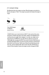
... is removed. Clear CMOS Jumper (CLRMOS1) (see p.7, No. 29) 2-pin Jumper CLRMOS1 allows you to default setup, please turn off the computer and unplug the power cord from the power supply. 2.5 Jumpers Setup The illustration shows how jumpers are setup. English 18
... is removed. Clear CMOS Jumper (CLRMOS1) (see p.7, No. 29) 2-pin Jumper CLRMOS1 allows you to default setup, please turn off the computer and unplug the power cord from the power supply. 2.5 Jumpers Setup The illustration shows how jumpers are setup. English 18
User Manual
Page 28
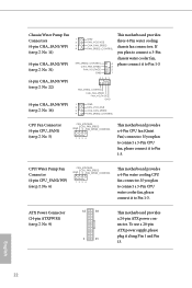
... CPU_FAN2/WP) (see p.7, No. 5) FAN_VOLTAGE CPU_FAN_SPEED GND FAN_SPEED_CONTROL 1 2 3 4 This motherboard provides a 4-Pin CPU fan (Quiet Fan) connector. ATX Power Connector (24-pin ATXPWR1) (see p.7, No. 16) 1 GND 2 FAN_VOLTAGE 3 CHA_FAN_SPEED 4 FAN_SPEED_CONTROL FAN_SPEED_CONTROL 4 CHA_FAN_SPEED 3 FAN_VOLTAGE 2 GND 1 43 21 ...9) 12 24 1 13 This motherboard provides a 24-pin ATX power connector. If you plan to connect a 3-Pin CPU water cooler fan, please connect it to Pin 1-3. To use a 20-pin ATX power supply, please plug it to connect a 3-Pin CPU fan, please ...
... CPU_FAN2/WP) (see p.7, No. 5) FAN_VOLTAGE CPU_FAN_SPEED GND FAN_SPEED_CONTROL 1 2 3 4 This motherboard provides a 4-Pin CPU fan (Quiet Fan) connector. ATX Power Connector (24-pin ATXPWR1) (see p.7, No. 16) 1 GND 2 FAN_VOLTAGE 3 CHA_FAN_SPEED 4 FAN_SPEED_CONTROL FAN_SPEED_CONTROL 4 CHA_FAN_SPEED 3 FAN_VOLTAGE 2 GND 1 43 21 ...9) 12 24 1 13 This motherboard provides a 24-pin ATX power connector. If you plan to connect a 3-Pin CPU water cooler fan, please connect it to Pin 1-3. To use a 20-pin ATX power supply, please plug it to connect a 3-Pin CPU fan, please ...
User Manual
Page 29
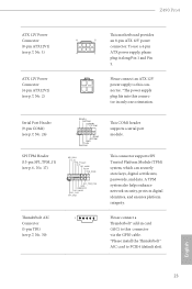
...pin TB1) (see p.7, No. 30) Please connect a Thunderbolt™ add-in card (AIC) to PCIE4 (default slot). Z490 Pro4 ATX 12V Power Connector (8-pin ATX12V1) (see p.7, No. 1) ATX 12V Power Connector (4-pin ATX12V2) (see p.6, No. 17) RRXD1 DDTR#1 DDSR#1 CCTS#1 1 RRI#1 RRTS#1 GND TTXD1 DDCD#1 SPI_DQ3...SPI_TPM_CS# GND RSMRST# SPI_MISO SPI_CS0 SPI_DQ2 This COM1 header supports a serial port module. Please connect an ATX 12V power supply to this connector. *The power supply plug fits into this connector via the GPIO cable. *Please install the Thunderbolt™ AIC card to this connector...
...pin TB1) (see p.7, No. 30) Please connect a Thunderbolt™ add-in card (AIC) to PCIE4 (default slot). Z490 Pro4 ATX 12V Power Connector (8-pin ATX12V1) (see p.7, No. 1) ATX 12V Power Connector (4-pin ATX12V2) (see p.6, No. 17) RRXD1 DDTR#1 DDSR#1 CCTS#1 1 RRI#1 RRTS#1 GND TTXD1 DDCD#1 SPI_DQ3...SPI_TPM_CS# GND RSMRST# SPI_MISO SPI_CS0 SPI_DQ2 This COM1 header supports a serial port module. Please connect an ATX 12V power supply to this connector. *The power supply plug fits into this connector via the GPIO cable. *Please install the Thunderbolt™ AIC card to this connector...
User Manual
Page 31
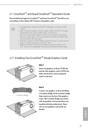
Z490 Pro4 2.7 CrossFireXTM and Quad CrossFireXTM Operation Guide This motherboard supports CrossFireXTM and Quad CrossFireXTM that your power supply unit (PSU) can provide at least the minimum power your system requires. Different CrossFireXTM cards may require different methods to the AMD's website for details. 4. Please refer to your graphics card driver supports AMD ...
Z490 Pro4 2.7 CrossFireXTM and Quad CrossFireXTM Operation Guide This motherboard supports CrossFireXTM and Quad CrossFireXTM that your power supply unit (PSU) can provide at least the minimum power your system requires. Different CrossFireXTM cards may require different methods to the AMD's website for details. 4. Please refer to your graphics card driver supports AMD ...
User Manual
Page 54
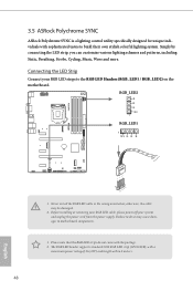
RGB_LED2 RGB_LED1 1 12V G R B Z490 PRO4 1 B 12V G R 1. Before installing or removing your RGB LED cable, please power off your RGB LED strips to build their own stylish colorful lighting system. Never install the RGB LED cable in the wrong orientation; 3.5 ASRock Polychrome SYNC ASRock Polychrome SYNC is a lighting control utility... Static, Breathing, Strobe, Cycling, Music, Wave and more. Connecting the LED Strip Connect your system and unplug the power cord from the power supply. The RGB LED header supports standard 5050 RGB LED strip (12V/G/R/B), with the package. 2.
RGB_LED2 RGB_LED1 1 12V G R B Z490 PRO4 1 B 12V G R 1. Before installing or removing your RGB LED cable, please power off your RGB LED strips to build their own stylish colorful lighting system. Never install the RGB LED cable in the wrong orientation; 3.5 ASRock Polychrome SYNC ASRock Polychrome SYNC is a lighting control utility... Static, Breathing, Strobe, Cycling, Music, Wave and more. Connecting the LED Strip Connect your system and unplug the power cord from the power supply. The RGB LED header supports standard 5050 RGB LED strip (12V/G/R/B), with the package. 2.
User Manual
Page 55
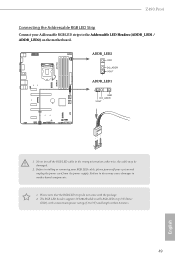
... the Addressable LED Headers (ADDR_LED1 / ADDR_LED2) on the motherboard. The RGB LED header supports WS2812B addressable RGB LED strip (5V/Data/ GND), with the package. 2. Z490 PRO4 Z490 Pro4 Connecting the Addressable RGB LED Strip Connect your system and unplug the power cord from the power supply. ADDR_LED2 ADDR_LED1 1 GND DO_ADDR VOUT 1 1.
... the Addressable LED Headers (ADDR_LED1 / ADDR_LED2) on the motherboard. The RGB LED header supports WS2812B addressable RGB LED strip (5V/Data/ GND), with the package. 2. Z490 PRO4 Z490 Pro4 Connecting the Addressable RGB LED Strip Connect your system and unplug the power cord from the power supply. ADDR_LED2 ADDR_LED1 1 GND DO_ADDR VOUT 1 1.
User Manual
Page 72
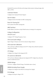
... voltage for the processor by the external voltage refulator. DRAM Voltage Use this to skip DRAM memory training for the DRAM Activating Power Supply. PCH Voltage Configure the chipset voltage (1.0V). 66 English [Enabled] The system will allow performing realtime memory timing changes after ...GPU voltage droop when the system is [Auto]. Reset On Training Fail Reset system if the MRC training fails. DRAM Activating Power Supply Configure the voltage for booting faster. Command Tristate Configure the Command Tristate Support. CPU Load-Line Calibration CPU Load-Line Calibration ...
... voltage for the processor by the external voltage refulator. DRAM Voltage Use this to skip DRAM memory training for the DRAM Activating Power Supply. PCH Voltage Configure the chipset voltage (1.0V). 66 English [Enabled] The system will allow performing realtime memory timing changes after ...GPU voltage droop when the system is [Auto]. Reset On Training Fail Reset system if the MRC training fails. DRAM Activating Power Supply Configure the voltage for booting faster. Command Tristate Configure the Command Tristate Support. CPU Load-Line Calibration CPU Load-Line Calibration ...

