
User Manual
Page 4
...1.2 Specifications 2 1.3 Motherboard Layout 8 1.4 I/O Panel 10 Chapter 2 Installation 12 2.1 Installing the CPU 13 2.2 Installing the CPU Fan and Heatsink 16 2.3 Installing Memory Modules (DIMM) 17 2.4 Expansion Slots (PCI Express Slots) 19 2.5 Jumpers Setup 20 2.6 Onboard Headers and Connectors 21 2.7 SLITM and Quad SLITM Operation Guide 26 2.7.1 Installing Two SLITM-Ready Graphics Cards 26 2.7.2 Driver Installation and Setup 28 2.8 CrossFireXTM , 3-Way CrossFireXTM and Quad CrossFireXTM Operation Guide 29 2.8.1 Installing Two CrossFireXTM-Ready Graphics Cards 29...
...1.2 Specifications 2 1.3 Motherboard Layout 8 1.4 I/O Panel 10 Chapter 2 Installation 12 2.1 Installing the CPU 13 2.2 Installing the CPU Fan and Heatsink 16 2.3 Installing Memory Modules (DIMM) 17 2.4 Expansion Slots (PCI Express Slots) 19 2.5 Jumpers Setup 20 2.6 Onboard Headers and Connectors 21 2.7 SLITM and Quad SLITM Operation Guide 26 2.7.1 Installing Two SLITM-Ready Graphics Cards 26 2.7.2 Driver Installation and Setup 28 2.8 CrossFireXTM , 3-Way CrossFireXTM and Quad CrossFireXTM Operation Guide 29 2.8.1 Installing Two CrossFireXTM-Ready Graphics Cards 29...
User Manual
Page 7
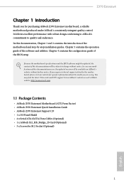
... updated, the content of this documentation, Chapter 1 and 2 contains the introduction of this motherboard, please visit our website for specific information about the model you are using. You may find the latest VGA cards and CPU support list on ASRock's website without notice. ASRock website http://www.asrock.com. 1.1 Package Contents • ASRock Z370 Extreme4 Motherboard (ATX Form Factor) • ASRock Z370 Extreme4 Quick Installation Guide • ASRock Z370 Extreme4 Support CD • 1 x I/O Panel Shield • 4 x Serial ATA (SATA) Data Cables (Optional...
... updated, the content of this documentation, Chapter 1 and 2 contains the introduction of this motherboard, please visit our website for specific information about the model you are using. You may find the latest VGA cards and CPU support list on ASRock's website without notice. ASRock website http://www.asrock.com. 1.1 Package Contents • ASRock Z370 Extreme4 Motherboard (ATX Form Factor) • ASRock Z370 Extreme4 Quick Installation Guide • ASRock Z370 Extreme4 Support CD • 1 x I/O Panel Shield • 4 x Serial ATA (SATA) Data Cables (Optional...

User Manual
Page 9
... Gold Series Audio Caps - 120dB SNR DAC with max. shared memory 1024MB * The size of maximum shared memory may vary from different operating systems. • Three graphics output options: D-Sub, DVI-D and HDMI • Supports Triple Monitor • Supports HDMI with Differential Amplifier - Z370 Extreme4 Graphics Audio • Intel® UHD Graphics Built-in Visuals and the VGA outputs can be supported only with processors which are GPU integrated. • Supports Intel...
... Gold Series Audio Caps - 120dB SNR DAC with max. shared memory 1024MB * The size of maximum shared memory may vary from different operating systems. • Three graphics output options: D-Sub, DVI-D and HDMI • Supports Triple Monitor • Supports HDMI with Differential Amplifier - Z370 Extreme4 Graphics Audio • Intel® UHD Graphics Built-in Visuals and the VGA outputs can be supported only with processors which are GPU integrated. • Supports Intel...
User Manual
Page 11
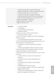
... boot disks ** Supports ASRock U.2 Kit Connector • 1 x COM Port Header • 1 x TPM Header • 1 x Power LED and Speaker Header • 1 x RGB LED Header * Supports in total up to 12V/3A, 36W LED Strip • 1 x CPU Fan Connector (4-pin) * The CPU Fan Connector supports the CPU fan of maximum 1A (12W) fan power. • 1 x CPU Optional/Water Pump Fan Connector (4-pin) * The CPU Optional/Water Pump Fan supports the water cooler fan of maximum 1.5A (18W) fan power. • 2 x Chassis Fan Connectors (4-pin) (Smart Fan Speed Control) • 1 x Chassis Optional/Water Pump Fan...
... boot disks ** Supports ASRock U.2 Kit Connector • 1 x COM Port Header • 1 x TPM Header • 1 x Power LED and Speaker Header • 1 x RGB LED Header * Supports in total up to 12V/3A, 36W LED Strip • 1 x CPU Fan Connector (4-pin) * The CPU Fan Connector supports the CPU fan of maximum 1A (12W) fan power. • 1 x CPU Optional/Water Pump Fan Connector (4-pin) * The CPU Optional/Water Pump Fan supports the water cooler fan of maximum 1.5A (18W) fan power. • 2 x Chassis Fan Connectors (4-pin) (Smart Fan Speed Control) • 1 x Chassis Optional/Water Pump Fan...

User Manual
Page 12
... Panel Type C USB 3.1 Gen1 Header (ASMedia ASM1074 hub) • 2 x AMI UEFI Legal BIOS with multilingual GUI support (1 x Main BIOS and 1 x Backup BIOS) • Supports Secure Backup UEFI Technology • ACPI 6.0 Compliant wake up events • SMBIOS 2.7 Support • CPU Core/Cache, GT Core/Cache, DRAM, PCH 1.0V, VCCIO, VCCST, VCCSA, VCCPLL, CPU Internal PLL, GT PLL, Ring PLL, System Agent PLL, Memory Controller PLL Voltage Multi-adjustment • Temperature Sensing: CPU, CPU Optional/Water Pump, Chassis, Chassis Optional/Water Pump Fans • Fan Tachometer: CPU, CPU Optional...
... Panel Type C USB 3.1 Gen1 Header (ASMedia ASM1074 hub) • 2 x AMI UEFI Legal BIOS with multilingual GUI support (1 x Main BIOS and 1 x Backup BIOS) • Supports Secure Backup UEFI Technology • ACPI 6.0 Compliant wake up events • SMBIOS 2.7 Support • CPU Core/Cache, GT Core/Cache, DRAM, PCH 1.0V, VCCIO, VCCST, VCCSA, VCCPLL, CPU Internal PLL, GT PLL, Ring PLL, System Agent PLL, Memory Controller PLL Voltage Multi-adjustment • Temperature Sensing: CPU, CPU Optional/Water Pump, Chassis, Chassis Optional/Water Pump Fans • Fan Tachometer: CPU, CPU Optional...
User Manual
Page 15
...11 SATA3 Connectors (SATA3_2_3) 12 SATA3 Connectors (SATA3_0_1) 13 SATA3 Connectors (SATA3_A1_A2) 14 System Panel Header (PANEL1) 15 Power LED and Speaker Header (SPK_PLED1) 16 Chassis Fan / Waterpump Fan Connector (CHA_FAN3/W_PUMP) 17 COM Port Header (COM1) 18 USB 2.0 Header (USB_5_6) 19 USB 2.0 Header (USB_1_2) 20 USB 2.0 Header (USB_3_4) 21 TPM Header (TPMS1) 22 Chassis Fan Connector (CHA_FAN2) 23 Thunderbolt AIC Connector (TB1) 24 RGB LED Header (RGB_LED) 25 Clear CMOS Jumper (CLRMOS1) 26 Front Panel Audio Header (HD_AUDIO1) 27 Chassis Fan Connector (CHA_FAN1) 9 English Z370 Extreme4 No.
...11 SATA3 Connectors (SATA3_2_3) 12 SATA3 Connectors (SATA3_0_1) 13 SATA3 Connectors (SATA3_A1_A2) 14 System Panel Header (PANEL1) 15 Power LED and Speaker Header (SPK_PLED1) 16 Chassis Fan / Waterpump Fan Connector (CHA_FAN3/W_PUMP) 17 COM Port Header (COM1) 18 USB 2.0 Header (USB_5_6) 19 USB 2.0 Header (USB_1_2) 20 USB 2.0 Header (USB_3_4) 21 TPM Header (TPMS1) 22 Chassis Fan Connector (CHA_FAN2) 23 Thunderbolt AIC Connector (TB1) 24 RGB LED Header (RGB_LED) 25 Clear CMOS Jumper (CLRMOS1) 26 Front Panel Audio Header (HD_AUDIO1) 27 Chassis Fan Connector (CHA_FAN1) 9 English Z370 Extreme4 No.

User Manual
Page 25
... 3-Way CrossFireXTM Mode x8 x8 x4 English For a better thermal environment, please connect a chassis fan to the motherboard's chassis fan connector (CHA_FAN1, CHA_FAN2 or CHA_FAN3 ) when using multiple graphics cards. 19 Please read the documentation of the expansion card and make sure that the power supply is switched off or the power cord is used for PCI Express x4 lane width graphics cards. PCIE5 (PCIe 3.0 x1 slot) is used for the card before you start the installation.
... 3-Way CrossFireXTM Mode x8 x8 x4 English For a better thermal environment, please connect a chassis fan to the motherboard's chassis fan connector (CHA_FAN1, CHA_FAN2 or CHA_FAN3 ) when using multiple graphics cards. 19 Please read the documentation of the expansion card and make sure that the power supply is switched off or the power cord is used for PCI Express x4 lane width graphics cards. PCIE5 (PCIe 3.0 x1 slot) is used for the card before you start the installation.
User Manual
Page 27
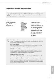
... RESET# GND HDLEDHDLED+ Connect the power button, reset button and system status indicator on the chassis front panel. The LED is on when the hard drive is operating. The LED is off (S5). The LED is on when the system is reading or writing data. When connecting your system using the power button. Z370 Extreme4 2.6 Onboard Headers and Connectors Onboard headers and connectors are matched correctly. RESET (Reset Button): Connect to the motherboard. Do NOT place jumper caps over the headers and connectors...
... RESET# GND HDLEDHDLED+ Connect the power button, reset button and system status indicator on the chassis front panel. The LED is on when the hard drive is operating. The LED is off (S5). The LED is on when the system is reading or writing data. When connecting your system using the power button. Z370 Extreme4 2.6 Onboard Headers and Connectors Onboard headers and connectors are matched correctly. RESET (Reset Button): Connect to the motherboard. Do NOT place jumper caps over the headers and connectors...
User Manual
Page 31
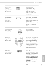
... GPIO cable. *Please install the Thunderbolt™ AIC card to page 49 for further instructions on on this header. 25 English To use a 4-pin ATX power supply, please plug it along Pin 1 and Pin 5. 1 Please connect a Thunderbolt™ add-in the wrong orienta- Z370 Extreme4 ATX 12V Power Connector (8-pin ATX12V1) (see p.8, No. 1) Thunderbolt AIC Connectors (5-pin TB1) (see p.8, No. 23) Serial Port Header (9-pin COM1) (see p.8, No. 17) TPM Header (17-pin TPMS1) (see p.8, No. 21) RGB LED Header (4-pin...
... GPIO cable. *Please install the Thunderbolt™ AIC card to page 49 for further instructions on on this header. 25 English To use a 4-pin ATX power supply, please plug it along Pin 1 and Pin 5. 1 Please connect a Thunderbolt™ add-in the wrong orienta- Z370 Extreme4 ATX 12V Power Connector (8-pin ATX12V1) (see p.8, No. 1) Thunderbolt AIC Connectors (5-pin TB1) (see p.8, No. 23) Serial Port Header (9-pin COM1) (see p.8, No. 17) TPM Header (17-pin TPMS1) (see p.8, No. 21) RGB LED Header (4-pin...

User Manual
Page 35
... other graphics card to three identical PCI Express x16 graphics cards. 1. Make sure that your power supply unit (PSU) can provide at least the minimum power your graphics card driver supports AMD CrossFireXTM technology. Make sure that your system requires. Z370 Extreme4 2.8 CrossFireXTM , 3-Way CrossFireXTM and Quad CrossFireXTM Operation Guide This motherboard supports CrossFireXTM, 3-way CrossFireXTM and Quad CrossFireXTM that allows you to install up to PCIE4 slot. Please refer to AMD graphics card manuals for...
... other graphics card to three identical PCI Express x16 graphics cards. 1. Make sure that your power supply unit (PSU) can provide at least the minimum power your graphics card driver supports AMD CrossFireXTM technology. Make sure that your system requires. Z370 Extreme4 2.8 CrossFireXTM , 3-Way CrossFireXTM and Quad CrossFireXTM Operation Guide This motherboard supports CrossFireXTM, 3-way CrossFireXTM and Quad CrossFireXTM that allows you to install up to PCIE4 slot. Please refer to AMD graphics card manuals for...
User Manual
Page 38
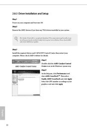
... is an optional download. Please check AMD's website for details. AMD Catalyst Control Center Step 4 Double-click the AMD Catalyst Control Center icon in your graphics card and click Apply. We recommend using this utility to uninstall any VGA drivers installed in the Windows® system tray. Select the GPU number according to installation. 2.8.3 Driver Installation and Setup Step 1 Power on your computer. Please check AMD's website for AMD driver updates. Then select Enable AMD CrossFireX...
... is an optional download. Please check AMD's website for details. AMD Catalyst Control Center Step 4 Double-click the AMD Catalyst Control Center icon in your graphics card and click Apply. We recommend using this utility to uninstall any VGA drivers installed in the Windows® system tray. Select the GPU number according to installation. 2.8.3 Driver Installation and Setup Step 1 Power on your computer. Please check AMD's website for AMD driver updates. Then select Enable AMD CrossFireX...
User Manual
Page 45
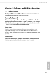
... the motherboard's features. The CD automatically displays the Main Menu if "AUTORUN" is enabled in the Support CD to install it. 39 English If the Main Menu does not appear automatically, locate and double click on the file "ASRSETUP.EXE" in your CD-ROM drive. Z370 Extreme4 Chapter 3 Software and Utilities Operation 3.1 Installing Drivers The Support CD that comes with the motherboard contains necessary drivers and useful utilities that the motherboard supports. Therefore, the drivers you install can work...
... the motherboard's features. The CD automatically displays the Main Menu if "AUTORUN" is enabled in the Support CD to install it. 39 English If the Main Menu does not appear automatically, locate and double click on the file "ASRSETUP.EXE" in your CD-ROM drive. Z370 Extreme4 Chapter 3 Software and Utilities Operation 3.1 Installing Drivers The Support CD that comes with the motherboard contains necessary drivers and useful utilities that the motherboard supports. Therefore, the drivers you install can work...

User Manual
Page 76
..., and I/O performance. VT-d Intel® Virtualization Technology for PCIE2. 70 English 4.6.2 Chipset Configuration Primary Graphics Adapter Select a primary VGA. Set this item to Dynamic to allow TOLUD to be decoded in Above 4G Address Space (only if the system supports 64 bit PCI decoding). PCIE1 Link Speed Select the link speed for PCIE1. Top of Lower Usable Dram Set the maximum value of the installed graphic controller.
..., and I/O performance. VT-d Intel® Virtualization Technology for PCIE2. 70 English 4.6.2 Chipset Configuration Primary Graphics Adapter Select a primary VGA. Set this item to Dynamic to allow TOLUD to be decoded in Above 4G Address Space (only if the system supports 64 bit PCI decoding). PCIE1 Link Speed Select the link speed for PCIE1. Top of Lower Usable Dram Set the maximum value of the installed graphic controller.

User Manual
Page 78
... onboard network interface controller (Intel® I219V). Onboard HD Audio Enable/disable onboard HD audio. Set to Auto to boot up when the power recovers. Front Panel Enable/disable front panel HD audio. Onboard HDMI HD Audio Enable audio for power saving when the computer is selected, the power will start to enable onboard HD audio and automatically disable it when a sound card is installed. WAN Radio Enable/disable the WiFi module's connectivity. Restore on /off when the power recovers. If [Power Off] is shut down. Deep Sleep Configure deep sleep mode...
... onboard network interface controller (Intel® I219V). Onboard HD Audio Enable/disable onboard HD audio. Set to Auto to boot up when the power recovers. Front Panel Enable/disable front panel HD audio. Onboard HDMI HD Audio Enable audio for power saving when the computer is selected, the power will start to enable onboard HD audio and automatically disable it when a sound card is installed. WAN Radio Enable/disable the WiFi module's connectivity. Restore on /off when the power recovers. If [Power Off] is shut down. Deep Sleep Configure deep sleep mode...

User Manual
Page 80
ASMedia SATA3 Mode [AHCI] Supports new features that improve performance. M2_1/ SATA3_0_1 Switch [Auto] M2_1/SATA3_0_1 auto switch [Force_SATA] Switch to SATA3_0_1 [Force_M2_1] Switch to M2_1 M2_2/ SATA3_4_5 Switch [Auto] M2_2/SATA3_4_5 auto switch [Force_SATA] Switch to SATA3_4_5 [Force_M2_1] Switch to M2_2 74 English Third Party SATA 3 Controller Enable or disable the third party SATA3 controller.
ASMedia SATA3 Mode [AHCI] Supports new features that improve performance. M2_1/ SATA3_0_1 Switch [Auto] M2_1/SATA3_0_1 auto switch [Force_SATA] Switch to SATA3_0_1 [Force_M2_1] Switch to M2_1 M2_2/ SATA3_4_5 Switch [Auto] M2_2/SATA3_4_5 auto switch [Force_SATA] Switch to SATA3_4_5 [Force_M2_1] Switch to M2_2 74 English Third Party SATA 3 Controller Enable or disable the third party SATA3 controller.

User Manual
Page 82
Serial Port Address Select the address of the Serial port. PS2 Y-Cable Enable the PS2 Y-Cable or set this option to Auto. 76 English 4.6.5 Super IO Configuration Serial Port Enable or disable the Serial port.
Serial Port Address Select the address of the Serial port. PS2 Y-Cable Enable the PS2 Y-Cable or set this option to Auto. 76 English 4.6.5 Super IO Configuration Serial Port Enable or disable the Serial port.
User Manual
Page 87
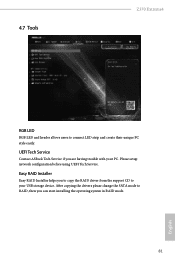
After copying the drivers please change the SATA mode to connect LED strip and create their unique PC style easily. 4.7 Tools Z370 Extreme4 RGB LED RGB LED and header allows users to RAID, then you can start installing the operating system in RAID mode. 81 English Easy RAID Installer Easy RAID Installer helps you are having trouble with your USB storage device. Please setup network configuration before using UEFI Tech Service. UEFI Tech Service Contact ASRock Tech Service if you to copy the RAID driver from the support CD to your PC.
After copying the drivers please change the SATA mode to connect LED strip and create their unique PC style easily. 4.7 Tools Z370 Extreme4 RGB LED RGB LED and header allows users to RAID, then you can start installing the operating system in RAID mode. 81 English Easy RAID Installer Easy RAID Installer helps you are having trouble with your USB storage device. Please setup network configuration before using UEFI Tech Service. UEFI Tech Service Contact ASRock Tech Service if you to copy the RAID driver from the support CD to your PC.
User Manual
Page 88
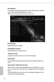
... Flash Save UEFI files in your UEFI. Internet Flash - DHCP (Auto IP), Auto ASRock Internet Flash downloads and updates the latest UEFI firmware version from our servers for the Boot Manager. Please setup network configuration before using Internet Flash. *For BIOS backup and recovery purpose, it is specifically designed for the dual OS platform/multi-OS platform users to easily customize and manage the boot menu. *Please connect more than one boot devices to wait for you. Boot Manager Timeout Enable/disable the Boot...
... Flash Save UEFI files in your UEFI. Internet Flash - DHCP (Auto IP), Auto ASRock Internet Flash downloads and updates the latest UEFI firmware version from our servers for the Boot Manager. Please setup network configuration before using Internet Flash. *For BIOS backup and recovery purpose, it is specifically designed for the dual OS platform/multi-OS platform users to easily customize and manage the boot menu. *Please connect more than one boot devices to wait for you. Boot Manager Timeout Enable/disable the Boot...

User Manual
Page 89
... Setting Enable or disable sound effects in the setup utility. Normally, the system will take over. Network Configuration Use this to update the backup BIOS manually. However if the active BIOS is currently activated. Users may refer to the BIOS LEDs (BIOS_A_LED or BIOS_B_LED) to the secondary flash ROM. Z370 Extreme4 Secure Backup UEFI Whenever one of the ROM images are not able to configure internet connection settings for Internet Flash. This motherboard has two BIOS chips, an active BIOS...
... Setting Enable or disable sound effects in the setup utility. Normally, the system will take over. Network Configuration Use this to update the backup BIOS manually. However if the active BIOS is currently activated. Users may refer to the BIOS LEDs (BIOS_A_LED or BIOS_B_LED) to the secondary flash ROM. Z370 Extreme4 Secure Backup UEFI Whenever one of the ROM images are not able to configure internet connection settings for Internet Flash. This motherboard has two BIOS chips, an active BIOS...

User Manual
Page 93
... and press enter to enable or disable support for the user account. You may set or change the supervisor/user password for the administrator account. User Password Set or change the password for the system. Secure Boot Use this item to remove the password. Supervisor Password Set or change the password for Secure Boot. Users are unable to remove the password. Disable this option to change the settings in the UEFI Setup Utility. Intel(R) Platform Trust Technology Enable/disable Intel PTT in the UEFI Setup Utility. Z370 Extreme4 4.9 Security Screen In this...
... and press enter to enable or disable support for the user account. You may set or change the supervisor/user password for the administrator account. User Password Set or change the password for the system. Secure Boot Use this item to remove the password. Supervisor Password Set or change the password for Secure Boot. Users are unable to remove the password. Disable this option to change the settings in the UEFI Setup Utility. Intel(R) Platform Trust Technology Enable/disable Intel PTT in the UEFI Setup Utility. Z370 Extreme4 4.9 Security Screen In this...


