
User Manual
Page 4
...1.3 Motherboard Layout 6 1.4 I/O Panel 8 Chapter 2 Installation 10 2.1 Installing the CPU 11 2.2 Installing the CPU Fan and Heatsink 14 2.3 Installing Memory Modules (DIMM) 15 2.4 Expansion Slots (PCI Express Slots) 17 2.5 Jumpers Setup 18 2.6 Onboard Headers and Connectors 19 2.7 SLITM and Quad SLITM Operation Guide 23 2.7.1 Installing Two SLITM-Ready Graphics Cards 23 2.7.2 Driver Installation and Setup 25 2.8 CrossFireXTM , 3-Way CrossFireXTM and Quad CrossFireXTM Operation Guide 26 2.8.1 Installing Two CrossFireXTM-Ready Graphics Cards 26 2.8.2 Installing Three...
...1.3 Motherboard Layout 6 1.4 I/O Panel 8 Chapter 2 Installation 10 2.1 Installing the CPU 11 2.2 Installing the CPU Fan and Heatsink 14 2.3 Installing Memory Modules (DIMM) 15 2.4 Expansion Slots (PCI Express Slots) 17 2.5 Jumpers Setup 18 2.6 Onboard Headers and Connectors 19 2.7 SLITM and Quad SLITM Operation Guide 23 2.7.1 Installing Two SLITM-Ready Graphics Cards 23 2.7.2 Driver Installation and Setup 25 2.8 CrossFireXTM , 3-Way CrossFireXTM and Quad CrossFireXTM Operation Guide 26 2.8.1 Installing Two CrossFireXTM-Ready Graphics Cards 26 2.8.2 Installing Three...
User Manual
Page 5
... Drivers 33 3.2 A-Tuning 34 3.3 ASRock Live Update & APP Shop 38 3.3.1 UI Overview 38 3.3.2 Apps 39 3.3.3 BIOS & Drivers 42 3.3.4 Setting 43 3.4 Enabling USB Ports for Windows® 7 Installation 44 Chapter 4 UEFI SETUP UTILITY 47 4.1 Introduction 47 4.2 EZ Mode 48 4.3 Advanced Mode 49 4.3.1 UEFI Menu Bar 49 4.3.2 Navigation Keys 50 4.4 Main Screen 51 4.5 OC Tweaker Screen 52 4.6 Advanced Screen 61 4.6.1 CPU Coniguration 62 4.6.2 Chipset Coniguration 64 4.6.3 Storage Coniguration 66 4.6.4 Super IO Coniguration 67 4.6.5 ACPI Coniguration 68 4.6.6 USB...
... Drivers 33 3.2 A-Tuning 34 3.3 ASRock Live Update & APP Shop 38 3.3.1 UI Overview 38 3.3.2 Apps 39 3.3.3 BIOS & Drivers 42 3.3.4 Setting 43 3.4 Enabling USB Ports for Windows® 7 Installation 44 Chapter 4 UEFI SETUP UTILITY 47 4.1 Introduction 47 4.2 EZ Mode 48 4.3 Advanced Mode 49 4.3.1 UEFI Menu Bar 49 4.3.2 Navigation Keys 50 4.4 Main Screen 51 4.5 OC Tweaker Screen 52 4.6 Advanced Screen 61 4.6.1 CPU Coniguration 62 4.6.2 Chipset Coniguration 64 4.6.3 Storage Coniguration 66 4.6.4 Super IO Coniguration 67 4.6.5 ACPI Coniguration 68 4.6.6 USB...
User Manual
Page 7
...; ASRock Z170M Extreme4 Quick Installation Guide • ASRock Z170M Extreme4 Support CD • 2 x Serial ATA (SATA) Data Cables (Optional) • 1 x I/O Panel Shield • 1 x Screw for purchasing ASRock Z170M Extreme4 motherboard, a reliable motherboard produced under ASRock's consistently stringent quality control. In this motherboard, please visit our website for speciic information about the model you are using. Chapter 3 contains the operation guide of the BIOS setup. In case any modiications of this documentation occur, the updated version will be available on ASRock...
...; ASRock Z170M Extreme4 Quick Installation Guide • ASRock Z170M Extreme4 Support CD • 2 x Serial ATA (SATA) Data Cables (Optional) • 1 x I/O Panel Shield • 1 x Screw for purchasing ASRock Z170M Extreme4 motherboard, a reliable motherboard produced under ASRock's consistently stringent quality control. In this motherboard, please visit our website for speciic information about the model you are using. Chapter 3 contains the operation guide of the BIOS setup. In case any modiications of this documentation occur, the updated version will be available on ASRock...
User Manual
Page 9
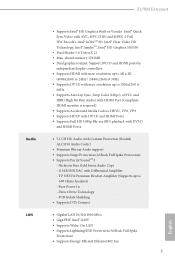
...) @ 30Hz • Supports DVI-D with max. Direct Drive Technology - resolution up to 600 Ohms headsets) - shared memory 1792MB • Dual graphics output: Support DVI-D and HDMI ports by independent display controllers • Supports HDMI with Diferential Ampliier - TI® NE5532 Premium Headset Ampliier (Supports up to 1920x1200 @ 60Hz • Supports Auto Lip Sync, Deep Color (12bpc), xvYCC and HBR (High Bit Rate Audio) with HDMI Port (Compliant HDMI monitor is required) • Supports Accelerated Media...
...) @ 30Hz • Supports DVI-D with max. Direct Drive Technology - resolution up to 600 Ohms headsets) - shared memory 1792MB • Dual graphics output: Support DVI-D and HDMI ports by independent display controllers • Supports HDMI with Diferential Ampliier - TI® NE5532 Premium Headset Ampliier (Supports up to 1920x1200 @ 60Hz • Supports Auto Lip Sync, Deep Color (12bpc), xvYCC and HBR (High Bit Rate Audio) with HDMI Port (Compliant HDMI monitor is required) • Supports Accelerated Media...
User Manual
Page 10
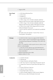
... Hot Plug * If M2_1 is occupied by a SATA-type M.2 device, SATA3_0 and SATA3_1 will be disabled. • 1 x Ultra M.2 Socket, supports type 2242/2260/2280 M.2 SATA3 6.0 Gb/s module and M.2 PCI Express module up to Gen3 x4 (32 Gb/s)** ** Supports NVMe SSD as boot disks ** Supports ASRock U.2 Kit English Connector • 1 x COM Port Header • 1 x TPM Header • 1 x Chassis Intrusion and Speaker Header • 1 x CPU Fan Connector (4-pin) (Smart Fan Speed Control) • 2 x Chassis Fan Connectors (4-pin) (Smart Fan Speed Con- trol) • 1 x 24 pin ATX Power Connector •...
... Hot Plug * If M2_1 is occupied by a SATA-type M.2 device, SATA3_0 and SATA3_1 will be disabled. • 1 x Ultra M.2 Socket, supports type 2242/2260/2280 M.2 SATA3 6.0 Gb/s module and M.2 PCI Express module up to Gen3 x4 (32 Gb/s)** ** Supports NVMe SSD as boot disks ** Supports ASRock U.2 Kit English Connector • 1 x COM Port Header • 1 x TPM Header • 1 x Chassis Intrusion and Speaker Header • 1 x CPU Fan Connector (4-pin) (Smart Fan Speed Control) • 2 x Chassis Fan Connectors (4-pin) (Smart Fan Speed Con- trol) • 1 x 24 pin ATX Power Connector •...
User Manual
Page 11
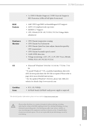
... Extreme4 BIOS Feature Hardware Monitor OS Certiications • 1 x USB 3.0 Header (Supports 2 USB 3.0 ports) (Supports ESD Protection (ASRock Full Spike Protection)) • AMI UEFI Legal BIOS with overclocking, including adjusting the setting in the BIOS, applying Untied Overclocking Technology, or using third-party overclocking tools. English 5 Please refer to the components and devices of your own risk and expense. adjustment • CPU/Chassis temperature sensing • CPU/Chassis Fan Tachometer • CPU/Chassis Quiet Fan (Auto adjust chassis fan speed by overclocking...
... Extreme4 BIOS Feature Hardware Monitor OS Certiications • 1 x USB 3.0 Header (Supports 2 USB 3.0 ports) (Supports ESD Protection (ASRock Full Spike Protection)) • AMI UEFI Legal BIOS with overclocking, including adjusting the setting in the BIOS, applying Untied Overclocking Technology, or using third-party overclocking tools. English 5 Please refer to the components and devices of your own risk and expense. adjustment • CPU/Chassis temperature sensing • CPU/Chassis Fan Tachometer • CPU/Chassis Quiet Fan (Auto adjust chassis fan speed by overclocking...
User Manual
Page 23
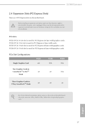
...you start the installation. Z170M Extreme4 2.4 Expansion Slots (PCI Express Slots) here are 4 PCI Express slots on the motherboard. PCIe Slot Conigurations Single Graphics Card PCIE1 x16 PCIE3 N/A PCIE4 N/A Two Graphics Cards in CrossFireXTM or SLITM x8 Mode x8 N/A hree Graphics Cards in 3-Way CrossFireXTM Mode x8 x8 x4 For a better thermal environment, please connect a chassis fan to the motherboard's chassis fan connector (CHA_FAN1 or CHA_FAN2) when using multiple graphics cards. Before installing an expansion card, please make necessary hardware settings for PCI Express x1...
...you start the installation. Z170M Extreme4 2.4 Expansion Slots (PCI Express Slots) here are 4 PCI Express slots on the motherboard. PCIe Slot Conigurations Single Graphics Card PCIE1 x16 PCIE3 N/A PCIE4 N/A Two Graphics Cards in CrossFireXTM or SLITM x8 Mode x8 N/A hree Graphics Cards in 3-Way CrossFireXTM Mode x8 x8 x4 For a better thermal environment, please connect a chassis fan to the motherboard's chassis fan connector (CHA_FAN1 or CHA_FAN2) when using multiple graphics cards. Before installing an expansion card, please make necessary hardware settings for PCI Express x1...
User Manual
Page 24
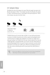
... the power supply. 2.5 Jumpers Setup he illustration shows a 3-pin jumper whose pin1 and pin2 are setup. When the jumper cap is placed on the pins, the jumper is "Short". To clear and reset the system parameters to clear the data in CMOS. Please be noted that the password, date, time, and user default proile will be detected. Clear CMOS Jumper (CLRMOS1) (see p.6, No. 16) Default Clear CMOS CLRMOS1 allows you update the BIOS. If no jumper cap...
... the power supply. 2.5 Jumpers Setup he illustration shows a 3-pin jumper whose pin1 and pin2 are setup. When the jumper cap is placed on the pins, the jumper is "Short". To clear and reset the system parameters to clear the data in CMOS. Please be noted that the password, date, time, and user default proile will be detected. Clear CMOS Jumper (CLRMOS1) (see p.6, No. 16) Default Clear CMOS CLRMOS1 allows you update the BIOS. If no jumper cap...
User Manual
Page 25
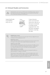
... the hard drive activity LED on the chassis front panel. HDLED (Hard Drive Activity LED): Connect to this header, make sure the wire assignments and the pin assignments are NOT jumpers. Z170M Extreme4 2.6 Onboard Headers and Connectors Onboard headers and connectors are matched correctly. Note the positive and negative pins before connecting the cables. he front panel design may conigure the way to the power status indicator on the chassis front panel. PLED (System Power LED): Connect to turn of power switch, reset switch, power LED, hard drive activity LED, speaker...
... the hard drive activity LED on the chassis front panel. HDLED (Hard Drive Activity LED): Connect to this header, make sure the wire assignments and the pin assignments are NOT jumpers. Z170M Extreme4 2.6 Onboard Headers and Connectors Onboard headers and connectors are matched correctly. Note the positive and negative pins before connecting the cables. he front panel design may conigure the way to the power status indicator on the chassis front panel. PLED (System Power LED): Connect to turn of power switch, reset switch, power LED, hard drive activity LED, speaker...
User Manual
Page 29
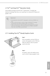
... graphics card to the PCI Express graphics cards. 23 English You should only use a NVIDIA® certiied PSU. It is recommended to two identical PCI Express x16 graphics cards. Z170M Extreme4 2.7 SLITM and Quad SLITM Operation Guide his motherboard supports NVIDIA® SLITM and Quad SLITM (Scalable Link Interface) technology that allows you to install up to use identical SLITM-ready graphics cards that are properly seated on the slots. Requirements 1. Download the drivers...
... graphics card to the PCI Express graphics cards. 23 English You should only use a NVIDIA® certiied PSU. It is recommended to two identical PCI Express x16 graphics cards. Z170M Extreme4 2.7 SLITM and Quad SLITM Operation Guide his motherboard supports NVIDIA® SLITM and Quad SLITM (Scalable Link Interface) technology that allows you to install up to use identical SLITM-ready graphics cards that are properly seated on the slots. Requirements 1. Download the drivers...
User Manual
Page 32
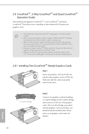
Please refer to PCIE3 slot. Download the drivers from the AMD's website: www.amd.com 3. Please refer to the AMD's website for detailed installation guide. 2.8.1 Installing Two CrossFireXTM-Ready Graphics Cards Step 1 Insert one graphics card into PCIE1 slot and the other graphics card to AMD graphics card manuals for details. 4. Make sure that the cards are AMD certiied. 2. 2.8 CrossFireXTM , 3-Way CrossFireXTM and Quad CrossFireXTM Operation Guide his motherboard supports CrossFireXTM, 3-way CrossFireXTM and Quad CrossFireXTM...
Please refer to PCIE3 slot. Download the drivers from the AMD's website: www.amd.com 3. Please refer to the AMD's website for detailed installation guide. 2.8.1 Installing Two CrossFireXTM-Ready Graphics Cards Step 1 Insert one graphics card into PCIE1 slot and the other graphics card to AMD graphics card manuals for details. 4. Make sure that the cards are AMD certiied. 2. 2.8 CrossFireXTM , 3-Way CrossFireXTM and Quad CrossFireXTM Operation Guide his motherboard supports CrossFireXTM, 3-way CrossFireXTM and Quad CrossFireXTM...
User Manual
Page 35
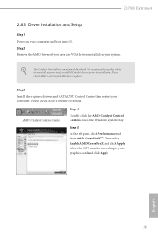
Z170M Extreme4 2.8.3 Driver Installation and Setup Step 1 Power on your graphics card and click Apply. he Catalyst Uninstaller is an optional download. hen select Enable AMD CrossFireX and click Apply. Select the GPU number according to installation. Please check AMD's website for details. Please check AMD's website for AMD driver updates. Step 5 In the let pane, click Performance and then AMD CrossFireXTM. We recommend using this utility to uninstall any VGA drivers installed in the...
Z170M Extreme4 2.8.3 Driver Installation and Setup Step 1 Power on your graphics card and click Apply. he Catalyst Uninstaller is an optional download. hen select Enable AMD CrossFireX and click Apply. Select the GPU number according to installation. Please check AMD's website for details. Please check AMD's website for AMD driver updates. Step 5 In the let pane, click Performance and then AMD CrossFireXTM. We recommend using this utility to uninstall any VGA drivers installed in the...
User Manual
Page 39
... double click on a speciic item then follow the order from top to bottom to install those required drivers. herefore, the drivers you install can work properly. "KB2720599": http://support.microsot.com/kb/2720599/en-us 33 English Utilities Menu he CD automatically displays the Main Menu if "AUTORUN" is enabled in the Support CD to display the menu. Z170M Extreme4 Chapter 3 Software and Utilities Operation 3.1 Installing Drivers he drivers compatible to your CD-ROM drive.
... double click on a speciic item then follow the order from top to bottom to install those required drivers. herefore, the drivers you install can work properly. "KB2720599": http://support.microsot.com/kb/2720599/en-us 33 English Utilities Menu he CD automatically displays the Main Menu if "AUTORUN" is enabled in the Support CD to display the menu. Z170M Extreme4 Chapter 3 Software and Utilities Operation 3.1 Installing Drivers he drivers compatible to your CD-ROM drive.
User Manual
Page 50
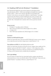
... Host Controller Interface (EHCI - hen use the new patched Windows® 7 installation USB drive to disabled ater the installation. 3.4 Enabling USB Ports for Windows® 7 Installation Intel® Braswell and Skylake has removed their motherboard won't work. USB3.0). You've got nothing: If you can install the Windows® 7 OS. Please set PS/S Simulator back to install Windows® 7 OS. 44 English Requirements • A Windows® 7 installation disk or USB drive • USB 3.0 drivers (included in the ASRock Support CD...
... Host Controller Interface (EHCI - hen use the new patched Windows® 7 installation USB drive to disabled ater the installation. 3.4 Enabling USB Ports for Windows® 7 Installation Intel® Braswell and Skylake has removed their motherboard won't work. USB3.0). You've got nothing: If you can install the Windows® 7 OS. Please set PS/S Simulator back to install Windows® 7 OS. 44 English Requirements • A Windows® 7 installation disk or USB drive • USB 3.0 drivers (included in the ASRock Support CD...

User Manual
Page 51
Step 3 Select the "Win7 Folder" from Step1 by clicking the red circle as shown as the picture below . If you are using ASRock's Support CD for the USB 3.0 driver, please select your system. Step 2 Extract the tool (Win7 USB Patcher) and launch it. Z170M Extreme4 Instructions Step 1 Insert the Windows® 7 installation disk or USB drive to your CD-ROM. 45 English Step 4 Select the "USB Driver Folder" by clicking the red circle as shown as the picture below .
Step 3 Select the "Win7 Folder" from Step1 by clicking the red circle as shown as the picture below . If you are using ASRock's Support CD for the USB 3.0 driver, please select your system. Step 2 Extract the tool (Win7 USB Patcher) and launch it. Z170M Extreme4 Instructions Step 1 Insert the Windows® 7 installation disk or USB drive to your CD-ROM. 45 English Step 4 Select the "USB Driver Folder" by clicking the red circle as shown as the picture below .

User Manual
Page 71
... GPU is installed. Restore on . It will be switched of memory that is selected, the power will start to disable the integrated graphics when an external graphics card is idle for lower power consumption. Onboard HD Audio Enable/disable onboard HD audio. Front Panel Enable/disable front panel HD audio. Z170M Extreme4 DMI ASPM Support his option enables/disables the ASPM support for all times. IGPU Multi-Monitor Select disable to boot up . Inte(R) Ethernet Connection I219-V Enable or disable the onboard network interface controller (Intel®...
... GPU is installed. Restore on . It will be switched of memory that is selected, the power will start to disable the integrated graphics when an external graphics card is idle for lower power consumption. Onboard HD Audio Enable/disable onboard HD audio. Front Panel Enable/disable front panel HD audio. Z170M Extreme4 DMI ASPM Support his option enables/disables the ASPM support for all times. IGPU Multi-Monitor Select disable to boot up . Inte(R) Ethernet Connection I219-V Enable or disable the onboard network interface controller (Intel®...
User Manual
Page 73
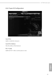
PS2 Y-Cable Enable the PS2 Y-Cable or set this option to Auto. 67 English 4.6.4 Super IO Coniguration Z170M Extreme4 Serial Port Enable or disable the Serial port. Serial Port Address Select the address of the Serial port.
PS2 Y-Cable Enable the PS2 Y-Cable or set this option to Auto. 67 English 4.6.4 Super IO Coniguration Z170M Extreme4 Serial Port Enable or disable the Serial port. Serial Port Address Select the address of the Serial port.
User Manual
Page 79
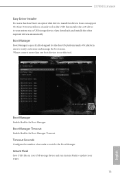
Z170M Extreme4 Easy Driver Installer For users that installs the LAN driver to your UEFI. 73 English Boot Manager Enable/disable the Boot Manager. Timeout Seconds Conigure the number of seconds to wait for the dual OS platform/multi-OS platform users to easily customize and manage the boot menu. *Please connect more than one boot devices to use this tool. Boot Manager Boot Manager is a handy tool in your USB storage device and run Instant Flash to...
Z170M Extreme4 Easy Driver Installer For users that installs the LAN driver to your UEFI. 73 English Boot Manager Enable/disable the Boot Manager. Timeout Seconds Conigure the number of seconds to wait for the dual OS platform/multi-OS platform users to easily customize and manage the boot menu. *Please connect more than one boot devices to use this tool. Boot Manager Boot Manager is a handy tool in your USB storage device and run Instant Flash to...
User Manual
Page 80
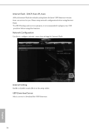
Internet Setting Enable or disable sound efects in your USB pen drive before using this to conigure internet connection settings for you. UEFI Download Server Select a server to plug in the setup utility. DHCP (Auto IP), Auto ASRock Internet Flash downloads and updates the latest UEFI irmware version from our servers for Internet Flash. Please setup network coniguration before using Internet Flash. *For BIOS backup and recovery purpose, it is recommended to download the UEFI irmware. 74 English Network Coniguration Use this function. Internet Flash -
Internet Setting Enable or disable sound efects in your USB pen drive before using this to conigure internet connection settings for you. UEFI Download Server Select a server to plug in the setup utility. DHCP (Auto IP), Auto ASRock Internet Flash downloads and updates the latest UEFI irmware version from our servers for Internet Flash. Please setup network coniguration before using Internet Flash. *For BIOS backup and recovery purpose, it is recommended to download the UEFI irmware. 74 English Network Coniguration Use this function. Internet Flash -
User Manual
Page 83
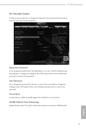
... to change the settings in the UEFI Setup Utility. You may set or change the settings in ME. Only the administrator has authority to change the supervisor/user password for the user account. Intel(R) Platform Trust Technology Enable/disable Intel PTT in the UEFI Setup Utility. User Password Set or change the password for Windows 8.1 Secure Boot. Z170M Extreme4 4.9 Security Screen In this section you may also clear the user password. Supervisor Password Set or change the password for the system. Secure Boot Use this option to enable or disable support...
... to change the settings in the UEFI Setup Utility. You may set or change the settings in ME. Only the administrator has authority to change the supervisor/user password for the user account. Intel(R) Platform Trust Technology Enable/disable Intel PTT in the UEFI Setup Utility. User Password Set or change the password for Windows 8.1 Secure Boot. Z170M Extreme4 4.9 Security Screen In this section you may also clear the user password. Supervisor Password Set or change the password for the system. Secure Boot Use this option to enable or disable support...


