

User Manual
Page 2
...damages (including damages for any errors or omissions that may apply, see www.dtsc.ca.gov/hazardouswaste/ perchlorate" ASRock Website: http://www.asrock.com When you discard the Lithium battery in California, USA, please follow the related regulations in this documentation. ...Speciications and information contained in any form or by any language, in this motherboard contains Perchlorate, a toxic substance controlled in Perchlorate Best Management Practices (BMP) regulations passed by ASRock. CALIFORNIA, USA ONLY he Lithium battery adopted on this documentation are used only...
...damages (including damages for any errors or omissions that may apply, see www.dtsc.ca.gov/hazardouswaste/ perchlorate" ASRock Website: http://www.asrock.com When you discard the Lithium battery in California, USA, please follow the related regulations in this documentation. ...Speciications and information contained in any form or by any language, in this motherboard contains Perchlorate, a toxic substance controlled in Perchlorate Best Management Practices (BMP) regulations passed by ASRock. CALIFORNIA, USA ONLY he Lithium battery adopted on this documentation are used only...
User Manual
Page 4
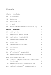
Contents Chapter 1 Introduction 1 1.1 Package Contents 1 1.2 Speciications 2 1.3 Motherboard Layout 7 1.4 I/O Panel 9 1.5 ASRock Front USB 3.1 Panel (for Z170 Extreme6+ only) 11 Chapter 2 Installation 14 2.1 Installing the CPU 15 2.2 Installing the CPU Fan and Heatsink 18 2.3 Installing Memory Modules (DIMM) 19 2.4 Expansion Slots (PCI Express ...
Contents Chapter 1 Introduction 1 1.1 Package Contents 1 1.2 Speciications 2 1.3 Motherboard Layout 7 1.4 I/O Panel 9 1.5 ASRock Front USB 3.1 Panel (for Z170 Extreme6+ only) 11 Chapter 2 Installation 14 2.1 Installing the CPU 15 2.2 Installing the CPU Fan and Heatsink 18 2.3 Installing Memory Modules (DIMM) 19 2.4 Expansion Slots (PCI Express ...

User Manual
Page 7
... documentation will be subject to change without further notice. Chapter 4 contains the coniguration guide of the motherboard and step-by-step installation guides. ASRock website http://www.asrock.com. 1.1 Package Contents • ASRock Z170 Extreme6+ / Z170 Extreme6 Motherboard (ATX Form Factor) • ASRock Z170 Extreme6+ / Z170 Extreme6 Quick Installation Guide • ASRock Z170 Extreme6+ / Z170 Extreme6 Support CD • 4 x Serial ATA (SATA) Data Cables (Optional) • 1 x I/O Panel Shield •...
... documentation will be subject to change without further notice. Chapter 4 contains the coniguration guide of the motherboard and step-by-step installation guides. ASRock website http://www.asrock.com. 1.1 Package Contents • ASRock Z170 Extreme6+ / Z170 Extreme6 Motherboard (ATX Form Factor) • ASRock Z170 Extreme6+ / Z170 Extreme6 Quick Installation Guide • ASRock Z170 Extreme6+ / Z170 Extreme6 Support CD • 4 x Serial ATA (SATA) Data Cables (Optional) • 1 x I/O Panel Shield •...
User Manual
Page 13
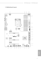
PS2 Keyboard /Mouse USB 3.0 T: USB5 B: USB6 1.3 Motherboard Layout 1 ATX12V1 CLRC BTN2 Z170 Extreme6+ / Z170 Extreme6 23 45 CHA_FAN1 CHA_FAN4 Power Reset 6 7 DVI1 HDMI1 DISPLAY1 DDR4_A1 (64 bit, 288-pin module) DDR4_A2 (64 bit, 288-pin ... 10 11 1 12 SATA3_A0_A1 PCIE2 13 LAN 14 SATA3_2_3 Ultra M.2 PCIe Gen3 x4 M2_1 SATA_EXP_0_1 SATA3_1_5 CT5 CT4 CT3 CT2 CT1 SATA3_0_4 15 Z170 Extreme6 Intel Purity SoundTM 3 PCIE3 Z170 16 PCIE4 17 PCIE5 HD_AUDIO1 1 COM1 1 PCIE6 TPMS1 1 1 T B1 USB1_2 1 USB3_4 1 BIOS_B1 BIOS_B_LED 128Mb BIOS BIOS_A_LED 128Mb BIOS BIOS_A1...
PS2 Keyboard /Mouse USB 3.0 T: USB5 B: USB6 1.3 Motherboard Layout 1 ATX12V1 CLRC BTN2 Z170 Extreme6+ / Z170 Extreme6 23 45 CHA_FAN1 CHA_FAN4 Power Reset 6 7 DVI1 HDMI1 DISPLAY1 DDR4_A1 (64 bit, 288-pin module) DDR4_A2 (64 bit, 288-pin ... 10 11 1 12 SATA3_A0_A1 PCIE2 13 LAN 14 SATA3_2_3 Ultra M.2 PCIe Gen3 x4 M2_1 SATA_EXP_0_1 SATA3_1_5 CT5 CT4 CT3 CT2 CT1 SATA3_0_4 15 Z170 Extreme6 Intel Purity SoundTM 3 PCIE3 Z170 16 PCIE4 17 PCIE5 HD_AUDIO1 1 COM1 1 PCIE6 TPMS1 1 1 T B1 USB1_2 1 USB3_4 1 BIOS_B1 BIOS_B_LED 128Mb BIOS BIOS_A_LED 128Mb BIOS BIOS_A1...

User Manual
Page 17
...devices, the device should support Type-C standards to install the ASRock Front USB 3.1 Panel into the drive bay of your motherboard. • 1 x USB 3.1 Type-C Port (10 Gb/s) (Supports ESD Protection (ASRock Full Spike Protection)) * his port supports power outputs up...On state (3 Amp) and Sleep state (1 Amp). * Some Type-C USB devices may only be charged by its own adapter. Z170 Extreme6+ / Z170 Extreme6 1.5 ASRock Front USB 3.1 Panel (for Z170 Extreme6+ only) Speciications Dimension • 75mm (W) x 42.8mm (H) x 148mm (L) Controller • ASMedia ASM1142 Controller Front Panel I/O...
...devices, the device should support Type-C standards to install the ASRock Front USB 3.1 Panel into the drive bay of your motherboard. • 1 x USB 3.1 Type-C Port (10 Gb/s) (Supports ESD Protection (ASRock Full Spike Protection)) * his port supports power outputs up...On state (3 Amp) and Sleep state (1 Amp). * Some Type-C USB devices may only be charged by its own adapter. Z170 Extreme6+ / Z170 Extreme6 1.5 ASRock Front USB 3.1 Panel (for Z170 Extreme6+ only) Speciications Dimension • 75mm (W) x 42.8mm (H) x 148mm (L) Controller • ASMedia ASM1142 Controller Front Panel I/O...

User Manual
Page 19
SATA3_4_5 SATA3_A1_A2 SATA3_A3_A4 SATA_EXP0 SATA3_1_3 SATA3_0_2 Step 8 Connect the other end of the USB Power Cable to the SATA Express Connector on the motherboard. Step 7 Connect the other end of the SATA Express Cable to the USB 2.0 Header on the motherboard. USB 3.0 USB 3.0 English Z170 Extreme6+ / Z170 Extreme6 Step 5 Screw ASRock Front USB 3.1 Panel to the SATA Power Connector. USB3_4 USB3_4 13 SATA3_4_5 SATA3_A1_A2 SATA3_A3_A4 SATA_EXP0 SATA3_1_3 SATA3_0_2 Step 6 Connect the PSU's SATA Power Cable to the drive bay with screws.
SATA3_4_5 SATA3_A1_A2 SATA3_A3_A4 SATA_EXP0 SATA3_1_3 SATA3_0_2 Step 8 Connect the other end of the USB Power Cable to the SATA Express Connector on the motherboard. Step 7 Connect the other end of the SATA Express Cable to the USB 2.0 Header on the motherboard. USB 3.0 USB 3.0 English Z170 Extreme6+ / Z170 Extreme6 Step 5 Screw ASRock Front USB 3.1 Panel to the SATA Power Connector. USB3_4 USB3_4 13 SATA3_4_5 SATA3_A1_A2 SATA3_A3_A4 SATA_EXP0 SATA3_1_3 SATA3_0_2 Step 6 Connect the PSU's SATA Power Cable to the drive bay with screws.

User Manual
Page 20
... the chassis, please do not touch the ICs. • Whenever you uninstall any motherboard settings. • Make sure to do so may damage the motherboard. 14 English Before you install the motherboard, study the coniguration of the following precautions before you handle the components. • ...the edges and do not overtighten the screws! Doing so may cause physical injuries and damages to motherboard components. • In order to avoid damage from static electricity to the motherboard's components, NEVER place your chassis to use a grounded wrist strap or touch a safety grounded ...
... the chassis, please do not touch the ICs. • Whenever you uninstall any motherboard settings. • Make sure to do so may damage the motherboard. 14 English Before you install the motherboard, study the coniguration of the following precautions before you handle the components. • ...the edges and do not overtighten the screws! Doing so may cause physical injuries and damages to motherboard components. • In order to avoid damage from static electricity to the motherboard's components, NEVER place your chassis to use a grounded wrist strap or touch a safety grounded ...

User Manual
Page 23
he cover must be placed if you wish to return the motherboard for ater service. 17 English Z170 Extreme6+ / Z170 Extreme6 Please save and replace the cover if the processor is removed.
he cover must be placed if you wish to return the motherboard for ater service. 17 English Z170 Extreme6+ / Z170 Extreme6 Please save and replace the cover if the processor is removed.

User Manual
Page 25
... the DIMM if you force the DIMM into a DDR4 slot; otherwise, this motherboard and DIMM may be damaged. Dual Channel Memory Coniguration Priority 1 2 3 DDR4_A1 Populated Populated DDR4_A2 Populated Populated DDR4_B1 Populated Populated DDR4_B2 ...-type) DDR4 DIMM pairs. 2. English 19 It is not allowed to activate Dual Channel Memory Technology with only one correct orientation. Z170 Extreme6+ / Z170 Extreme6 2.3 Installing Memory Modules (DIMM) his motherboard provides four 288-pin DDR4 (Double Data Rate 4) DIMM slots, and supports Dual Channel Memory Technology. 1.
... the DIMM if you force the DIMM into a DDR4 slot; otherwise, this motherboard and DIMM may be damaged. Dual Channel Memory Coniguration Priority 1 2 3 DDR4_A1 Populated Populated DDR4_A2 Populated Populated DDR4_B1 Populated Populated DDR4_B2 ...-type) DDR4 DIMM pairs. 2. English 19 It is not allowed to activate Dual Channel Memory Technology with only one correct orientation. Z170 Extreme6+ / Z170 Extreme6 2.3 Installing Memory Modules (DIMM) his motherboard provides four 288-pin DDR4 (Double Data Rate 4) DIMM slots, and supports Dual Channel Memory Technology. 1.

User Manual
Page 27
... N/A hree Graphics Cards in 3-Way CrossFireXTM Mode x8 x8 x4 English For a better thermal environment, please connect a chassis fan to the motherboard's chassis fan connector (CHA_FAN1, CHA_FAN2, CHA_FAN3 or CHA_FAN4) when using multiple graphics cards. 21 PCIe slots: PCIE1 (PCIe 3.0 x1 slot)... card and make necessary hardware settings for the card before you start the installation. Z170 Extreme6+ / Z170 Extreme6 2.4 Expansion Slots (PCI Express Slots) here are 6 PCI Express slots on the motherboard. Please read the documentation of or the power cord is used for PCI Express ...
... N/A hree Graphics Cards in 3-Way CrossFireXTM Mode x8 x8 x4 English For a better thermal environment, please connect a chassis fan to the motherboard's chassis fan connector (CHA_FAN1, CHA_FAN2, CHA_FAN3 or CHA_FAN4) when using multiple graphics cards. 21 PCIe slots: PCIE1 (PCIe 3.0 x1 slot)... card and make necessary hardware settings for the card before you start the installation. Z170 Extreme6+ / Z170 Extreme6 2.4 Expansion Slots (PCI Express Slots) here are 6 PCI Express slots on the motherboard. Please read the documentation of or the power cord is used for PCI Express ...
User Manual
Page 29
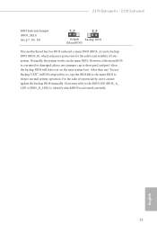
... boot. However, if the main BIOS is activated currently. Ater that, use a jumper cap to ensure normal system operation. Z170 Extreme6+ / Z170 Extreme6 BIOS Selection Jumper (BIOS_SEL1) (see p.7, No. 18) Default Backup BIOS (Main BIOS) his motherboard has two BIOS onboard, a main BIOS (BIOS_A) and a backup BIOS (BIOS_B), which BIOS is corrupted or damaged, please...
... boot. However, if the main BIOS is activated currently. Ater that, use a jumper cap to ensure normal system operation. Z170 Extreme6+ / Z170 Extreme6 BIOS Selection Jumper (BIOS_SEL1) (see p.7, No. 18) Default Backup BIOS (Main BIOS) his motherboard has two BIOS onboard, a main BIOS (BIOS_A) and a backup BIOS (BIOS_B), which BIOS is corrupted or damaged, please...

User Manual
Page 30
... activity LED on the chassis front panel. he front panel design may conigure the way to turn of your chassis front panel module to the motherboard. When connecting your system using the power switch. Placing jumper caps over these headers and connectors. Note the positive and negative pins before connecting the...
... activity LED on the chassis front panel. he front panel design may conigure the way to turn of your chassis front panel module to the motherboard. When connecting your system using the power switch. Placing jumper caps over these headers and connectors. Note the positive and negative pins before connecting the...

User Manual
Page 32
Each USB 3.0 header can support two ports. MIC_RET and OUT_RET are two headers on this motherboard. Front Panel Audio Header (9-pin HD_AUDIO1) (see p.7, No. 28) GND PRESENCE# MIC_RET OUT_RET 1 OUT2_L J_SENSE OUT2_R MIC2_R MIC2_L his header is one header on the ... OUT2_R and Audio_L (LIN) to MIC2_L. D. Each USB 2.0 header can support two ports. High Deinition Audio supports Jack Sensing, but the panel wire on this motherboard. E. C. If you use an AC'97 audio panel, please install it to the "FrontMic" Tab in our manual and chassis manual to Ground (GND). To...
Each USB 3.0 header can support two ports. MIC_RET and OUT_RET are two headers on this motherboard. Front Panel Audio Header (9-pin HD_AUDIO1) (see p.7, No. 28) GND PRESENCE# MIC_RET OUT_RET 1 OUT2_L J_SENSE OUT2_R MIC2_R MIC2_L his header is one header on the ... OUT2_R and Audio_L (LIN) to MIC2_L. D. Each USB 2.0 header can support two ports. High Deinition Audio supports Jack Sensing, but the panel wire on this motherboard. E. C. If you use an AC'97 audio panel, please install it to the "FrontMic" Tab in our manual and chassis manual to Ground (GND). To...

User Manual
Page 33
..., please connect it along Pin 1 and Pin 5. 27 English his motherboard pro- 3 2 vides a 4-Pin CPU fan 1 (Quiet Fan) connector. To use a 4-pin ATX power supply, please plug it along Pin 1 and Pin 13. Z170 Extreme6+ / Z170 Extreme6 Chassis Fan Connectors (4-pin CHA_FAN1) (see p.7, No. 4) GND FAN_VOLTAGE... CPU Fan Connectors (4-pin CPU_FAN1) (see p.7, No. 12) (4-pin CPU_FAN2) (see p.7, No. 1) 12 24 1 13 8 5 4 1 his motherboard provides a 24-pin ATX power connector. To use a 20-pin ATX power supply, please plug it to Pin 1-3. ATX Power Connector (24-pin ATXPWR1)...
..., please connect it along Pin 1 and Pin 5. 27 English his motherboard pro- 3 2 vides a 4-Pin CPU fan 1 (Quiet Fan) connector. To use a 4-pin ATX power supply, please plug it along Pin 1 and Pin 13. Z170 Extreme6+ / Z170 Extreme6 Chassis Fan Connectors (4-pin CHA_FAN1) (see p.7, No. 4) GND FAN_VOLTAGE... CPU Fan Connectors (4-pin CPU_FAN1) (see p.7, No. 12) (4-pin CPU_FAN2) (see p.7, No. 1) 12 24 1 13 8 5 4 1 his motherboard provides a 24-pin ATX power connector. To use a 20-pin ATX power supply, please plug it to Pin 1-3. ATX Power Connector (24-pin ATXPWR1)...

User Manual
Page 35
... p.9, No. 16) Clear CMOS Switch allows users to quickly reset the system. his function is workable only when you power of the system. Z170 Extreme6+ / Z170 Extreme6 2.7 Smart Switches he motherboard has three smart switches: Power Switch, Reset Switch and Clear CMOS Switch, allowing users to quickly turn on /of the system, reset the system...
... p.9, No. 16) Clear CMOS Switch allows users to quickly reset the system. his function is workable only when you power of the system. Z170 Extreme6+ / Z170 Extreme6 2.7 Smart Switches he motherboard has three smart switches: Power Switch, Reset Switch and Clear CMOS Switch, allowing users to quickly turn on /of the system, reset the system...

User Manual
Page 38
... two identical PCI Express x16 graphics cards. Download the drivers from the NVIDIA® website: www.nvidia.com 3. 2.9 SLITM and Quad SLITM Operation Guide his motherboard supports NVIDIA® SLITM and Quad SLITM (Scalable Link Interface) technology that allows you to install up to use identical SLITM-ready graphics cards that...
... two identical PCI Express x16 graphics cards. Download the drivers from the NVIDIA® website: www.nvidia.com 3. 2.9 SLITM and Quad SLITM Operation Guide his motherboard supports NVIDIA® SLITM and Quad SLITM (Scalable Link Interface) technology that allows you to install up to use identical SLITM-ready graphics cards that...

User Manual
Page 41
...CrossFire Bridge is recommended to your system requires. You should only use a AMD certiied PSU. Z170 Extreme6+ / Z170 Extreme6 2.10 CrossFireXTM , 3-Way CrossFireXTM and Quad CrossFireXTM Operation Guide his motherboard supports CrossFireXTM, 3-way CrossFireXTM and Quad CrossFireXTM that allows you to install up to PCIE4 slot...graphics card to three identical PCI Express x16 graphics cards. 1. If you pair a 12-pipe CrossFireXTM Edition card with this motherboard. Download the drivers from the AMD's website: www.amd.com 3. Please refer to AMD graphics card manuals for details.)...
...CrossFire Bridge is recommended to your system requires. You should only use a AMD certiied PSU. Z170 Extreme6+ / Z170 Extreme6 2.10 CrossFireXTM , 3-Way CrossFireXTM and Quad CrossFireXTM Operation Guide his motherboard supports CrossFireXTM, 3-way CrossFireXTM and Quad CrossFireXTM that allows you to install up to PCIE4 slot...graphics card to three identical PCI Express x16 graphics cards. 1. If you pair a 12-pipe CrossFireXTM Edition card with this motherboard. Download the drivers from the AMD's website: www.amd.com 3. Please refer to AMD graphics card manuals for details.)...

User Manual
Page 43
... card you purchase, not bundled with this motherboard. Please refer to your graphics card vendor for details.) Step 3 Connect a VGA cable or a DVI cable to the monitor connector or the DVI connector of the graphics card that the cards are properly seated on the slots. Z170 Extreme6+ / Z170 Extreme6 2.10.2 Installing Three CrossFireXTM-Ready Graphics...
... card you purchase, not bundled with this motherboard. Please refer to your graphics card vendor for details.) Step 3 Connect a VGA cable or a DVI cable to the monitor connector or the DVI connector of the graphics card that the cards are properly seated on the slots. Z170 Extreme6+ / Z170 Extreme6 2.10.2 Installing Three CrossFireXTM-Ready Graphics...

User Manual
Page 46
... the M.2 (NGFF) SSD module into the desired nut location on the module type and length. Please be used. E D C B A E D C B A C B A E D C B A Step 3 Move the standof based on the motherboard. he standof is placed at the nut location D by hand. Skip Step 3 and 4 and go straight to Step 5 if you are going to be aware...
... the M.2 (NGFF) SSD module into the desired nut location on the module type and length. Please be used. E D C B A E D C B A C B A E D C B A Step 3 Move the standof based on the motherboard. he standof is placed at the nut location D by hand. Skip Step 3 and 4 and go straight to Step 5 if you are going to be aware...

User Manual
Page 48
... to install it. Chapter 3 Software and Utilities Operation 3.1 Installing Drivers he Utilities Menu shows the application sotware that enhance the motherboard's features. To improve Windows 7 compatibility, please download and install the following hot ix provided by Microsot. Utilities Menu he Support... CD that comes with the motherboard contains necessary drivers and useful utilities that the motherboard supports. Drivers Menu he CD automatically displays the Main Menu if "AUTORUN" is enabled in the ...
... to install it. Chapter 3 Software and Utilities Operation 3.1 Installing Drivers he Utilities Menu shows the application sotware that enhance the motherboard's features. To improve Windows 7 compatibility, please download and install the following hot ix provided by Microsot. Utilities Menu he Support... CD that comes with the motherboard contains necessary drivers and useful utilities that the motherboard supports. Drivers Menu he CD automatically displays the Main Menu if "AUTORUN" is enabled in the ...

