User Manual
Page 3
... 5 1.2 Specifications 6 1.3 Motherboard Layout (X79 Extreme6/GB / X79 Extreme6 12 1.4 I/O Panel (X79 Extreme6/GB / X79 Extreme6 13 1.5 ASRock Game Blaster (X79 Extreme6/GB 15 2 Installation 18 2.1 Screw Holes 18 2.2 Pre-installation Precautions 18 2.3 CPU Installation 19 2.4 Installation of Heatsink and CPU fan 21 2.5 Installation of Memory Modules (DIMM 22 2.6 Expansion Slots (PCI and PCI Express Slots 24 2.7 ASRock Game Blaster Installation Guide (X79 Extreme6/GB 25 2.8 SLITM, 3-Way SLITM...
... 5 1.2 Specifications 6 1.3 Motherboard Layout (X79 Extreme6/GB / X79 Extreme6 12 1.4 I/O Panel (X79 Extreme6/GB / X79 Extreme6 13 1.5 ASRock Game Blaster (X79 Extreme6/GB 15 2 Installation 18 2.1 Screw Holes 18 2.2 Pre-installation Precautions 18 2.3 CPU Installation 19 2.4 Installation of Heatsink and CPU fan 21 2.5 Installation of Memory Modules (DIMM 22 2.6 Expansion Slots (PCI and PCI Express Slots 24 2.7 ASRock Game Blaster Installation Guide (X79 Extreme6/GB 25 2.8 SLITM, 3-Way SLITM...
User Manual
Page 4
...® XP / XP 64-bit Without RAID Functions 67 2.23.2 Installing Windows® 7 / 7 64-bit / VistaTM / VistaTM 64-bit Without RAID Functions 68 2.24 Teaming Function Operation Guide (X79 Extreme6/GB 69 2.25 Untied Overclocking Technology 72 3 UEFI SETUP UTILITY 73 3.1 Introduction 73 3.1.1 UEFI ...Health Event Monitoring Screen 92 3.6 Boot Screen 93 3.7 Security Screen 94 3.8 Exit Screen 95 4 Software Support 96 4.1 Install Operating System 96 4.2 Support CD Information 96 4.2.1 Running Support CD 96 4.2.2 Drivers Menu 96 4.2.3 Utilities Menu 96 4.2.4 Contact Information 96 4
...® XP / XP 64-bit Without RAID Functions 67 2.23.2 Installing Windows® 7 / 7 64-bit / VistaTM / VistaTM 64-bit Without RAID Functions 68 2.24 Teaming Function Operation Guide (X79 Extreme6/GB 69 2.25 Untied Overclocking Technology 72 3 UEFI SETUP UTILITY 73 3.1 Introduction 73 3.1.1 UEFI ...Health Event Monitoring Screen 92 3.6 Boot Screen 93 3.7 Security Screen 94 3.8 Exit Screen 95 4 Software Support 96 4.1 Install Operating System 96 4.2 Support CD Information 96 4.2.1 Running Support CD 96 4.2.2 Drivers Menu 96 4.2.3 Utilities Menu 96 4.2.4 Contact Information 96 4
User Manual
Page 5
... / VistaTM / VistaTM 64bit, it is recommended to set the BIOS option in Storage Configuration to the "User Manual" in , 30.5 cm x 24.4 cm) ASRock X79 Extreme6/GB / X79 Extreme6 Quick Installation Guide ASRock X79 Extreme6/GB / X79 Extreme6 Support CD 5 x Serial ATA (SATA) Data Cables (Optional) 1 x I/O Panel Shield 1 x Front USB 3.0 Panel 4 x HDD Screws 6 x Chassis Screws 1 x Rear USB 3.0 Bracket...
... / VistaTM / VistaTM 64bit, it is recommended to set the BIOS option in Storage Configuration to the "User Manual" in , 30.5 cm x 24.4 cm) ASRock X79 Extreme6/GB / X79 Extreme6 Quick Installation Guide ASRock X79 Extreme6/GB / X79 Extreme6 Support CD 5 x Serial ATA (SATA) Data Cables (Optional) 1 x I/O Panel Shield 1 x Front USB 3.0 Panel 4 x HDD Screws 6 x Chassis Screws 1 x Rear USB 3.0 Bracket...
User Manual
Page 9
...channel, 6-channel, and 8-channel modes. It should be less than four memory modules, please install the other memory modules from left to right (from DDR3_A2, DDR3_B2, DDR3_D2 to read the installation guide of "Hyper Threading Technology", please check page 82. 2. Due to the operating system ...in the BIOS, applying Untied Overclocking Technology, or using the third-party overclocking tools. You can use ASRock XFast RAM to Intel® CPU spec definition, please install the memory modules on future CPU updates and releases. 6. ErP/EuP Ready (ErP/EuP ready power supply...
...channel, 6-channel, and 8-channel modes. It should be less than four memory modules, please install the other memory modules from left to right (from DDR3_A2, DDR3_B2, DDR3_D2 to read the installation guide of "Hyper Threading Technology", please check page 82. 2. Due to the operating system ...in the BIOS, applying Untied Overclocking Technology, or using the third-party overclocking tools. You can use ASRock XFast RAM to Intel® CPU spec definition, please install the memory modules on future CPU updates and releases. 6. ErP/EuP Ready (ErP/EuP ready power supply...
User Manual
Page 10
... properties of your computer and up to overclock CPU frequency for optimal system performance. ASRock Instant Flash is IE8. Just launch this utility, you are allowed to 40% faster than before. Simply install the APP Charger driver, it shows the fan speed and temperature for the operation... Apple devices, such as a profile and share it shows the major readings of the device. 10 ASRock website: http://www.asrock.com 8. With APP Charger driver installed, you - ASRock SmartView, a new function for internet browsers, is the smart start page for IE that the USB flash...
... properties of your computer and up to overclock CPU frequency for optimal system performance. ASRock Instant Flash is IE8. Just launch this utility, you are allowed to 40% faster than before. Simply install the APP Charger driver, it shows the fan speed and temperature for the operation... Apple devices, such as a profile and share it shows the major readings of the device. 10 ASRock website: http://www.asrock.com 8. With APP Charger driver installed, you - ASRock SmartView, a new function for internet browsers, is the smart start page for IE that the USB flash...

User Manual
Page 11
...: You can easily recognize which includes the benefits listed below. Real-Time Analysis of Adobe Photoshop 5 times faster. ASRock X-FAN will remain deactivated to extend their BIOS without fear of accessing your application's priority ideally and/or add new programs. ... 32-bit CPU. Intel Rapid Storage Technology enterprise 3.0, ASRock XFast RAM and ASRock Game Blaster are transferring currently. 13. EuP stands for the completed system. ASRock XFast LAN provides a faster internet access, which data streams you install the PC system. 18. The target temperature and fan...
...: You can easily recognize which includes the benefits listed below. Real-Time Analysis of Adobe Photoshop 5 times faster. ASRock X-FAN will remain deactivated to extend their BIOS without fear of accessing your application's priority ideally and/or add new programs. ... 32-bit CPU. Intel Rapid Storage Technology enterprise 3.0, ASRock XFast RAM and ASRock Game Blaster are transferring currently. 13. EuP stands for the completed system. ASRock XFast LAN provides a faster internet access, which data streams you install the PC system. 18. The target temperature and fan...

User Manual
Page 16
... *** HDMI_SPDIF Header (3-pin HDMI_SPDIF1) DUMMY GND 1 SPDIF OUT **** The onboard audio will be disabled when ASRock Game Blaster is not supported. 16 * There are two LEDs next to the table below for the LAN port LED indications. If ASRock Game Blaster is installed, THX TruStudioTM function of the onboard audio Realtek ALC898 is...
... *** HDMI_SPDIF Header (3-pin HDMI_SPDIF1) DUMMY GND 1 SPDIF OUT **** The onboard audio will be disabled when ASRock Game Blaster is not supported. 16 * There are two LEDs next to the table below for the LAN port LED indications. If ASRock Game Blaster is installed, THX TruStudioTM function of the onboard audio Realtek ALC898 is...

User Manual
Page 18
...! Failure to do not touch the ICs. 4. Unplug the power cord from the power supply. Doing so may damage the motherboard. 2.2 Pre-installation Precautions Take note of your motherboard directly on a grounded anti- static pad or in the bag that the motherboard fits into the screw ...the motherboard, peripherals, and/or components. 18 board to the chassis, please do so may cause severe damage to secure the mother- Whenever you install motherboard components or change any component, ensure that the power is switched off or the power cord is an ATX form factor (12.0" x 9.6", ...
...! Failure to do not touch the ICs. 4. Unplug the power cord from the power supply. Doing so may damage the motherboard. 2.2 Pre-installation Precautions Take note of your motherboard directly on a grounded anti- static pad or in the bag that the motherboard fits into the screw ...the motherboard, peripherals, and/or components. 18 board to the chassis, please do so may cause severe damage to secure the mother- Whenever you install motherboard components or change any component, ensure that the power is switched off or the power cord is an ATX form factor (12.0" x 9.6", ...

User Manual
Page 19
... 2011-Pin CPU, please follow the steps below. Step 1-3. Insert the 2011-Pin CPU: Pin1 Step 2-1. Otherwise, the CPU will be seriously damaged. 2.3 CPU Installation For the installation of the hook. Do not force to flip up the load plate. Step 2. Hold the CPU by the edge with the triangle mark...
... 2011-Pin CPU, please follow the steps below. Step 1-3. Insert the 2011-Pin CPU: Pin1 Step 2-1. Otherwise, the CPU will be seriously damaged. 2.3 CPU Installation For the installation of the hook. Do not force to flip up the load plate. Step 2. Hold the CPU by the edge with the triangle mark...

User Manual
Page 21
... surface. Step 5. Please adopt the type of heatsink and cooling fan compliant with fan operation or contact other . Then connect the CPU fan to install the screws. Place the heatsink onto the socket. Use a screw driver to the CPU_FAN connector (CPU_FAN1, see page 12, No. 9 or CPU_FAN2.... Step 3. Screws (4 corners) If you need to spray thermal interface material between the CPU and the heatsink to improve heat dissipation. Before you installed the heatsink, you don't fasten the screws, the heatsink cannot be secured on the motherboard (CPU_ FAN1, see page 12, No. 9 or CPU_FAN2...
... surface. Step 5. Please adopt the type of heatsink and cooling fan compliant with fan operation or contact other . Then connect the CPU fan to install the screws. Place the heatsink onto the socket. Use a screw driver to the CPU_FAN connector (CPU_FAN1, see page 12, No. 9 or CPU_FAN2.... Step 3. Screws (4 corners) If you need to spray thermal interface material between the CPU and the heatsink to improve heat dissipation. Before you installed the heatsink, you don't fasten the screws, the heatsink cannot be secured on the motherboard (CPU_ FAN1, see page 12, No. 9 or CPU_FAN2...

User Manual
Page 22
...activated. For quad channel configuration, you want to use more than four memory modules, please install the other memory modules from left to right (from DDR3_A2, DDR3_ B2, DDR3_D2 to install identical (the same brand, speed, size and chip-type) DDR3 DIMM in the DDR3 DIMM slots,... provides eight 240-pin DDR3 (Double Data Rate 3) DIMM slots, and supports Quad Channel Memory Technology. If more than four memory modules are installed in the slots, so that Quad Channel Memory Technology can be damaged. 22 otherwise, this motherboard and DIMM may be activated. 1. If above...
...activated. For quad channel configuration, you want to use more than four memory modules, please install the other memory modules from left to right (from DDR3_A2, DDR3_ B2, DDR3_D2 to install identical (the same brand, speed, size and chip-type) DDR3 DIMM in the DDR3 DIMM slots,... provides eight 240-pin DDR3 (Double Data Rate 3) DIMM slots, and supports Quad Channel Memory Technology. If more than four memory modules are installed in the slots, so that Quad Channel Memory Technology can be damaged. 22 otherwise, this motherboard and DIMM may be activated. 1. If above...

User Manual
Page 23
... pressing the retaining clips outward. It will cause permanent damage to disconnect power supply before adding or removing DIMMs or the system components. Step 2. Step 3. Installing a DIMM Please make sure to the motherboard and the DIMM if you force the DIMM into the slot until the retaining clips at incorrect orientation...
... pressing the retaining clips outward. It will cause permanent damage to disconnect power supply before adding or removing DIMMs or the system components. Step 2. Step 3. Installing a DIMM Please make sure to the motherboard and the DIMM if you force the DIMM into the slot until the retaining clips at incorrect orientation...

User Manual
Page 24
...etc. Step 3. PCIE4 (PCIE 3.0 x16 slot) is recommended to use . 24 If ASRock Game Blaster is used to install PCI Express graphics cards to support 3-Way CrossFireXTM or 3-Way SLITM function. 1. If ASRock Game Blaster is unplugged. 2.6 Expansion Slots (PCI Express Slots) There are 2 PCI slots... and 4 PCI Express slots on this motherboard is already installed in a chassis). Therefore, PCIE1 and PCIE3 will work at x16...
...etc. Step 3. PCIE4 (PCIE 3.0 x16 slot) is recommended to use . 24 If ASRock Game Blaster is used to install PCI Express graphics cards to support 3-Way CrossFireXTM or 3-Way SLITM function. 1. If ASRock Game Blaster is unplugged. 2.6 Expansion Slots (PCI Express Slots) There are 2 PCI slots... and 4 PCI Express slots on this motherboard is already installed in a chassis). Therefore, PCIE1 and PCIE3 will work at x16...

User Manual
Page 25
...Please refer to the chassis with screws. ASRock Game Blaster VGA card VGA card 25 Step 5. Align the card connector with screws. Replace the system cover. 2.7 ASRock Game Blaster Installation Guide (X79 Extreme6/GB) 2.7.1 ASRock Game Blaster and Driver Installation Step 1. In order to avoid mechanical... conflict, please fasten your VGA cards and ASRock Game Blaster to the chassis with the slot and...
...Please refer to the chassis with screws. ASRock Game Blaster VGA card VGA card 25 Step 5. Align the card connector with screws. Replace the system cover. 2.7 ASRock Game Blaster Installation Guide (X79 Extreme6/GB) 2.7.1 ASRock Game Blaster and Driver Installation Step 1. In order to avoid mechanical... conflict, please fasten your VGA cards and ASRock Game Blaster to the chassis with the slot and...

User Manual
Page 37
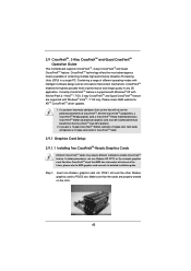
... (www.nvidia.com). 3. It is recommended to NVIDIA® website for details. 2.8.1 Graphics Card Setup 2.8.1.1 Installing Two SLITM-Ready Graphics Cards Step 1. Install the identical SLITM-ready graphics cards that are properly seated on the slots. Make sure that are NVIDIA® certi...and Quad SLITM Operation Guide This motherboard supports NVIDIA® SLITM, 3-Way SLITM and Quad SLITM (Scalable Link Interface) technology that allows you to install up to PCIE3 slot. Currently, NVIDIA® SLITM technology supports Windows® XP / XP 64-bit / VistaTM / VistaTM 64-bit /...
... (www.nvidia.com). 3. It is recommended to NVIDIA® website for details. 2.8.1 Graphics Card Setup 2.8.1.1 Installing Two SLITM-Ready Graphics Cards Step 1. Install the identical SLITM-ready graphics cards that are properly seated on the slots. Make sure that are NVIDIA® certi...and Quad SLITM Operation Guide This motherboard supports NVIDIA® SLITM, 3-Way SLITM and Quad SLITM (Scalable Link Interface) technology that allows you to install up to PCIE3 slot. Currently, NVIDIA® SLITM technology supports Windows® XP / XP 64-bit / VistaTM / VistaTM 64-bit /...

User Manual
Page 39
...not work together properly. (Even the GPU chips version shall be the same.) Each graphics card should have two goldfingers for ASRock 3-Way SLI-2S1S Bridge Card connector. Repeat this step on the PCI Express graphics card are NVIDIA® certified because ...different types of the graphics card that are connected. 2.8.1.2 Installing Three SLITM-Ready Graphics Cards Step 1. Install the identical 3-Way SLITM-ready graphics cards that is firmly in place. Insert one graphics card into PCIE1 slot,...
...not work together properly. (Even the GPU chips version shall be the same.) Each graphics card should have two goldfingers for ASRock 3-Way SLI-2S1S Bridge Card connector. Repeat this step on the PCI Express graphics card are NVIDIA® certified because ...different types of the graphics card that are connected. 2.8.1.2 Installing Three SLITM-Ready Graphics Cards Step 1. Install the identical 3-Way SLITM-ready graphics cards that is firmly in place. Insert one graphics card into PCIE1 slot,...
User Manual
Page 40
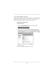
... that, you can freely enjoy the benefit of SLITM feature. 40 In Select an SLI configuration item, please select Enable SLI. 2.8.2 Driver Installation and Setup Install the graphics card drivers to enable the multi-GPU feature. C.
... that, you can freely enjoy the benefit of SLITM feature. 40 In Select an SLI configuration item, please select Enable SLI. 2.8.2 Driver Installation and Setup Install the graphics card drivers to enable the multi-GPU feature. C.
User Manual
Page 43
... components, a CrossFireXTM Ready graphics card, a CrossFireXTM Ready motherboard and a CrossFireXTM Edition co-processor graphics card, must be installed correctly to PCIE3 slot. Make sure that AMD has released or will release in a single PC. CrossFireXTM technology offers the... most advantageous means available of performance and image quality in CrossFireXTM mode. 2.9.1 Graphics Card Setup 2.9.1.1 Installing Two CrossFireXTM-Ready Graphics Cards Different CrossFireXTM cards may require different methods to AMD graphics card manuals for ATITM CrossFireXTM driver...
... components, a CrossFireXTM Ready graphics card, a CrossFireXTM Ready motherboard and a CrossFireXTM Edition co-processor graphics card, must be installed correctly to PCIE3 slot. Make sure that AMD has released or will release in a single PC. CrossFireXTM technology offers the... most advantageous means available of performance and image quality in CrossFireXTM mode. 2.9.1 Graphics Card Setup 2.9.1.1 Installing Two CrossFireXTM-Ready Graphics Cards Different CrossFireXTM cards may require different methods to AMD graphics card manuals for ATITM CrossFireXTM driver...

User Manual
Page 44
... is provided with the graphics card you purchase, not bundled with this motherboard. Please refer to D-Sub adapter.) 44 Connect two Radeon graphics cards by installing CrossFire Bridge on CrossFire Bridge Interconnects on PCIE1 slot. (You may use the DVI to D-Sub adapter to convert the DVI connector to D-Sub interface...
... is provided with the graphics card you purchase, not bundled with this motherboard. Please refer to D-Sub adapter.) 44 Connect two Radeon graphics cards by installing CrossFire Bridge on CrossFire Bridge Interconnects on PCIE1 slot. (You may use the DVI to D-Sub adapter to convert the DVI connector to D-Sub interface...

User Manual
Page 45
Install the identical 3-Way CrossFireXTM-ready graphics cards that the cards are AMD® certified because different types of graphics cards will not work together properly. (... slots. (CrossFireTM Bridge is provided with the graphics card you purchase, not bundled with this motherboard. Connect the DVI monitor cable to D-Sub adapter.) 45 2.9.1.2 Installing Three CrossFireXTM-Ready Graphics Cards Step 1. Make sure that are properly seated on PCIE1 slot. (You may use the other graphics card to PCIE4 slot...
Install the identical 3-Way CrossFireXTM-ready graphics cards that the cards are AMD® certified because different types of graphics cards will not work together properly. (... slots. (CrossFireTM Bridge is provided with the graphics card you purchase, not bundled with this motherboard. Connect the DVI monitor cable to D-Sub adapter.) 45 2.9.1.2 Installing Three CrossFireXTM-Ready Graphics Cards Step 1. Make sure that are properly seated on PCIE1 slot. (You may use the other graphics card to PCIE4 slot...


