User Manual
Page 7
PCIE x1 Gigabit LAN 10/100/1000 Mb/s - Supports Energy Efficient Ethernet 802.3az - Audio (X79 Extreme6) LAN Rear Panel I /O Panel - 1 x PS/2 Mouse Port - 1 x PS/2 Keyboard Port - 1 x Coaxial SPDIF Out Port - 1 x Optical SPDIF Out Port - 4 x Ready-to-Use USB 2.0 Ports - ... up to -Use USB 3.0 Ports - 1 x RJ-45 LAN Port with LED (ACT/LINK LED and SPEED LED) - 1 x IEEE 1394 Port - 1 x Clear CMOS Switch with LED - Premium Blu-ray audio support - Broadcom BCM57781 - Supports PXE I /O SATA3 USB3.0 Connector - 7.1 CH HD Audio with the bundled ASRock Game Blaster (X79 Extreme6/GB) -
PCIE x1 Gigabit LAN 10/100/1000 Mb/s - Supports Energy Efficient Ethernet 802.3az - Audio (X79 Extreme6) LAN Rear Panel I /O Panel - 1 x PS/2 Mouse Port - 1 x PS/2 Keyboard Port - 1 x Coaxial SPDIF Out Port - 1 x Optical SPDIF Out Port - 4 x Ready-to-Use USB 2.0 Ports - ... up to -Use USB 3.0 Ports - 1 x RJ-45 LAN Port with LED (ACT/LINK LED and SPEED LED) - 1 x IEEE 1394 Port - 1 x Clear CMOS Switch with LED - Premium Blu-ray audio support - Broadcom BCM57781 - Supports PXE I /O SATA3 USB3.0 Connector - 7.1 CH HD Audio with the bundled ASRock Game Blaster (X79 Extreme6/GB) -
User Manual
Page 8
... Feature Support CD Unique Feature Hardware Monitor - 1 x IEEE 1394 header - 1 x Power LED header - ASRock Instant Boot - ASRock XFast RAM (see CAUTION 13) - SLI/XFire power connector - 3 x USB 2.0 headers (support 6 USB 2.0 ports) - 1 x USB 3.0 header (supports 2 USB 3.0 ports) - 1 x Dr. Debug with LED - 1 x Clear CMOS Switch with LED - 1 x Power Switch with LED - 1 x Reset Switch with LED - 64Mb...
... Feature Support CD Unique Feature Hardware Monitor - 1 x IEEE 1394 header - 1 x Power LED header - ASRock Instant Boot - ASRock XFast RAM (see CAUTION 13) - SLI/XFire power connector - 3 x USB 2.0 headers (support 6 USB 2.0 ports) - 1 x USB 3.0 header (supports 2 USB 3.0 ports) - 1 x Dr. Debug with LED - 1 x Clear CMOS Switch with LED - 1 x Power Switch with LED - 1 x Reset Switch with LED - 64Mb...

User Manual
Page 12
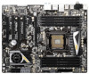
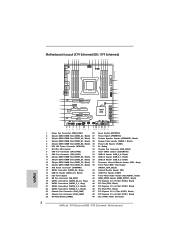
1.3 Motherboard Layout (X79 Extreme6/GB / X79 Extreme6) 1 2 34 5 6 7 89 10 11 12 13 24.4cm (9.6 in) PS2 Mouse PS2 Keyboard PWR_FAN1 ATX12V1 CPU_FAN2 CPU_FAN1 Clr CMOS AT X P W R 1 30.5cm (12.0 in) Coaxial SPDIF Optical SPDIF DDR3_C1 (64 bit, 240-pin module) DDR3_C2 (64 bit, 240...) 6 ATX 12V Power Connector (ATX12V1) 31 Dr. Debug 7 2011-Pin CPU Socket 32 Chassis Fan Connector (CHA_FAN3) 8 CPU Fan Connector (CPU_FAN2) 33 Clear CMOS Jumper (CLRCMOS1) 9 CPU Fan Connector (CPU_FAN1) 34 USB 2.0 Header (USB_8_9, Black) 10 240-pin DDR3 DIMM Slot (DDR3_D2, Black) 35 USB 2.0 ...
1.3 Motherboard Layout (X79 Extreme6/GB / X79 Extreme6) 1 2 34 5 6 7 89 10 11 12 13 24.4cm (9.6 in) PS2 Mouse PS2 Keyboard PWR_FAN1 ATX12V1 CPU_FAN2 CPU_FAN1 Clr CMOS AT X P W R 1 30.5cm (12.0 in) Coaxial SPDIF Optical SPDIF DDR3_C1 (64 bit, 240-pin module) DDR3_C2 (64 bit, 240...) 6 ATX 12V Power Connector (ATX12V1) 31 Dr. Debug 7 2011-Pin CPU Socket 32 Chassis Fan Connector (CHA_FAN3) 8 CPU Fan Connector (CPU_FAN2) 33 Clear CMOS Jumper (CLRCMOS1) 9 CPU Fan Connector (CPU_FAN1) 34 USB 2.0 Header (USB_8_9, Black) 10 240-pin DDR3 DIMM Slot (DDR3_D2, Black) 35 USB 2.0 ...
User Manual
Page 13
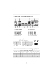
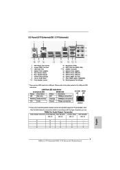
...100Mbps connection On Link Green 1Gbps connection LAN Port ** If you use 2-channel speaker, please connect the speaker's plug into "Front Speaker Jack". 1.4 I/O Panel (X79 Extreme6/GB / X79 Extreme6) 1 PS/2 Mouse Port (Green) 2 Coaxial SPDIF Out Port * 3 LAN RJ-45 Port 4 USB 2.0 Ports (USB45) 5 Side Speaker (Gray) 6 ... Port (IEEE 1394) eSATA3 Connector USB 2.0 Ports (USB01) USB 3.0 Ports (USB_23) USB 3.0 Ports (USB_01) Optical SPDIF Out Port Clear CMOS Switch (CLRCBTN) PS/2 Keyboard Port (Purple) * There are two LED next to the table below for connection details in accordance with the...
...100Mbps connection On Link Green 1Gbps connection LAN Port ** If you use 2-channel speaker, please connect the speaker's plug into "Front Speaker Jack". 1.4 I/O Panel (X79 Extreme6/GB / X79 Extreme6) 1 PS/2 Mouse Port (Green) 2 Coaxial SPDIF Out Port * 3 LAN RJ-45 Port 4 USB 2.0 Ports (USB45) 5 Side Speaker (Gray) 6 ... Port (IEEE 1394) eSATA3 Connector USB 2.0 Ports (USB01) USB 3.0 Ports (USB_23) USB 3.0 Ports (USB_01) Optical SPDIF Out Port Clear CMOS Switch (CLRCBTN) PS/2 Keyboard Port (Purple) * There are two LED next to the table below for connection details in accordance with the...

User Manual
Page 49
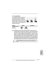
... a 3-pin jumper whose pin1 and pin2 are setup. If you update the BIOS. To clear and reset the system parameters to clear the data in CMOS. The Clear CMOS Switch has the same function as the Clear CMOS jumper. 49 However, please do the clear-CMOS action. Please be noted that the password, date, time, user default profi...
... a 3-pin jumper whose pin1 and pin2 are setup. If you update the BIOS. To clear and reset the system parameters to clear the data in CMOS. The Clear CMOS Switch has the same function as the Clear CMOS jumper. 49 However, please do the clear-CMOS action. Please be noted that the password, date, time, user default profi...

User Manual
Page 57
...to quickly turn on /off the system. 2.14 Smart Switches The motherboard has three smart switches: power switch, reset switch and clear CMOS switch, allowing users to quickly clear the CMOS values. 57 Reset Switch (RSTBTN) (see p.12 No. 27) Power Switch is a smart switch, allowing users to quickly ...turn on /off or reset the sytem clear the CMOS values. Power Switch (PWRBTN) (see p.12 No. 26) RESET Reset Switch is a smart ...
...to quickly turn on /off the system. 2.14 Smart Switches The motherboard has three smart switches: power switch, reset switch and clear CMOS switch, allowing users to quickly clear the CMOS values. 57 Reset Switch (RSTBTN) (see p.12 No. 27) Power Switch is a smart switch, allowing users to quickly ...turn on /off or reset the sytem clear the CMOS values. Power Switch (PWRBTN) (see p.12 No. 26) RESET Reset Switch is a smart ...
Quick Installation Guide
Page 2
... LED Header (PLED1) 6 ATX 12V Power Connector (ATX12V1) 31 Dr. Debug 7 2011-Pin CPU Socket 32 Chassis Fan Connector (CHA_FAN3) 8 CPU Fan Connector (CPU_FAN2) 33 Clear CMOS Jumper (CLRCMOS1) 9 CPU Fan Connector (CPU_FAN1) 34 USB 2.0 Header (USB_8_9, Black) 10 240-pin DDR3 DIMM Slot (DDR3_D2, Black) 35 USB 2.0 Header (USB_6_7, Black) 11... Slot (PCIE2, Black) 24 Chassis Fan Connector (CHA_FAN2) 48 PCI Express 3.0 x16 Slot (PCIE1, Black) 25 SPI Flash Memory (64Mb) 49 SLI / XFIRE Power Connector 2 ASRock X79 Extreme6/GB / X79 Extreme6 Motherboard English
... LED Header (PLED1) 6 ATX 12V Power Connector (ATX12V1) 31 Dr. Debug 7 2011-Pin CPU Socket 32 Chassis Fan Connector (CHA_FAN3) 8 CPU Fan Connector (CPU_FAN2) 33 Clear CMOS Jumper (CLRCMOS1) 9 CPU Fan Connector (CPU_FAN1) 34 USB 2.0 Header (USB_8_9, Black) 10 240-pin DDR3 DIMM Slot (DDR3_D2, Black) 35 USB 2.0 Header (USB_6_7, Black) 11... Slot (PCIE2, Black) 24 Chassis Fan Connector (CHA_FAN2) 48 PCI Express 3.0 x16 Slot (PCIE1, Black) 25 SPI Flash Memory (64Mb) 49 SLI / XFIRE Power Connector 2 ASRock X79 Extreme6/GB / X79 Extreme6 Motherboard English
Quick Installation Guide
Page 3
... Speaker Central / Bass Side Speaker (No. 9) (No. 6) (No. 7) (No. 5) 2 V -- -- -- 4 V V -- -- 6 V V V -- 8 V V V V 3 ASRock X79 Extreme6/GB / X79 Extreme6 Motherboard English LAN Port LED Indications Activity/Link LED SPEED LED Status Description Status Description ACT/LINK SPEED LED LED Off No Link Off 10Mbps... 1394) eSATA3 Connector USB 2.0 Ports (USB01) USB 3.0 Ports (USB_23) USB 3.0 Ports (USB_01) Optical SPDIF Out Port Clear CMOS Switch (CLRCBTN) PS/2 Keyboard Port (Purple) * There are two LED next to the table below for connection details in ...
... Speaker Central / Bass Side Speaker (No. 9) (No. 6) (No. 7) (No. 5) 2 V -- -- -- 4 V V -- -- 6 V V V -- 8 V V V V 3 ASRock X79 Extreme6/GB / X79 Extreme6 Motherboard English LAN Port LED Indications Activity/Link LED SPEED LED Status Description Status Description ACT/LINK SPEED LED LED Off No Link Off 10Mbps... 1394) eSATA3 Connector USB 2.0 Ports (USB01) USB 3.0 Ports (USB_23) USB 3.0 Ports (USB_01) Optical SPDIF Out Port Clear CMOS Switch (CLRCBTN) PS/2 Keyboard Port (Purple) * There are two LED next to the table below for connection details in ...

Quick Installation Guide
Page 10
...RJ-45 LAN Port with LED (ACT/LINK LED and SPEED LED) - 1 x IEEE 1394 Port - 1 x Clear CMOS Switch with LED - PCIE x1 Gigabit LAN 10/100/1000 Mb/s - Audio - 7.1 CH HD Audio with the bundled ASRock Game Blaster (X79 Extreme6/GB) - Supports Wake-On-LAN - Supports Dual LAN with Teaming function with Content Protection... Storage 3.0), NCQ, AHCI and Hot Plug functions - 5 x SATA3 6.0Gb/s connectors - 1 x IR header - 1 x CIR header - 1 x COM port header - 1 x HDMI_SPDIF header 10 ASRock X79 Extreme6/GB / X79 Extreme6 Motherboard Broadcom BCM57781 - Premium Blu-ray audio support -
...RJ-45 LAN Port with LED (ACT/LINK LED and SPEED LED) - 1 x IEEE 1394 Port - 1 x Clear CMOS Switch with LED - PCIE x1 Gigabit LAN 10/100/1000 Mb/s - Audio - 7.1 CH HD Audio with the bundled ASRock Game Blaster (X79 Extreme6/GB) - Supports Wake-On-LAN - Supports Dual LAN with Teaming function with Content Protection... Storage 3.0), NCQ, AHCI and Hot Plug functions - 5 x SATA3 6.0Gb/s connectors - 1 x IR header - 1 x CIR header - 1 x COM port header - 1 x HDMI_SPDIF header 10 ASRock X79 Extreme6/GB / X79 Extreme6 Motherboard Broadcom BCM57781 - Premium Blu-ray audio support -
Quick Installation Guide
Page 11
...) 11 ASRock X79 Extreme6/GB / X79 Extreme6 Motherboard SMBIOS 2.3.1 Support - ASRock XFast LAN (see CAUTION 13) - Hybrid Booster: - Chassis Temperature Sensing - Supports "Plug and Play" - ACPI 1.1 Compliance Wake Up Events - ASRock Extreme Tuning Utility (AXTU) (see CAUTION 8) - ASRock Instant Flash...1 x Dr. Debug with LED Smart Switch - 1 x Clear CMOS Switch with LED - 1 x Power Switch with LED - 1 x Reset Switch with LED BIOS Feature - 64Mb AMI UEFI Legal BIOS with GUI support - ASRock SmartView (see CAUTION 16) - CPU Frequency Stepless Control (see ...
...) 11 ASRock X79 Extreme6/GB / X79 Extreme6 Motherboard SMBIOS 2.3.1 Support - ASRock XFast LAN (see CAUTION 13) - Hybrid Booster: - Chassis Temperature Sensing - Supports "Plug and Play" - ACPI 1.1 Compliance Wake Up Events - ASRock Extreme Tuning Utility (AXTU) (see CAUTION 8) - ASRock Instant Flash...1 x Dr. Debug with LED Smart Switch - 1 x Clear CMOS Switch with LED - 1 x Power Switch with LED - 1 x Reset Switch with LED BIOS Feature - 64Mb AMI UEFI Legal BIOS with GUI support - ASRock SmartView (see CAUTION 16) - CPU Frequency Stepless Control (see ...
Quick Installation Guide
Page 45
... is placed on CLRCMOS1 for 5 seconds. English 45 ASRock X79 Extreme6/GB / X79 Extreme6 Motherboard Jumper Clear CMOS Jumper (CLRCMOS1) (see p.2, No. 33) Setting Default Clear CMOS Description Note: CLRCMOS1 allows you update the BIOS. To clear and reset the system parameters to clear the data in CMOS. If you need to clear the CMOS when you just finish updating the BIOS, you...
... is placed on CLRCMOS1 for 5 seconds. English 45 ASRock X79 Extreme6/GB / X79 Extreme6 Motherboard Jumper Clear CMOS Jumper (CLRCMOS1) (see p.2, No. 33) Setting Default Clear CMOS Description Note: CLRCMOS1 allows you update the BIOS. To clear and reset the system parameters to clear the data in CMOS. If you need to clear the CMOS when you just finish updating the BIOS, you...

Quick Installation Guide
Page 53
English 53 ASRock X79 Extreme6/GB / X79 Extreme6 Motherboard Clear CMOS Switch (CLRCBTN) (see p.3 No. 17) clr CMOS Clear CMOS Switch is a smart switch, allowing users to quickly turn on /off or reset the sytem clear the CMOS values. Power Switch (PWRBTN) (see p.2 No. 26) RESET Reset Switch is a smart switch, ...allowing users to quickly reset the system. 2.12 Smart Switches The motherboard has three smart switches: power switch, reset switch and clear CMOS switch, allowing users to quickly turn on /off the system. Reset Switch (RSTBTN) (see p.2 No. 27) Power Switch is...
English 53 ASRock X79 Extreme6/GB / X79 Extreme6 Motherboard Clear CMOS Switch (CLRCBTN) (see p.3 No. 17) clr CMOS Clear CMOS Switch is a smart switch, allowing users to quickly turn on /off or reset the sytem clear the CMOS values. Power Switch (PWRBTN) (see p.2 No. 26) RESET Reset Switch is a smart switch, ...allowing users to quickly reset the system. 2.12 Smart Switches The motherboard has three smart switches: power switch, reset switch and clear CMOS switch, allowing users to quickly turn on /off the system. Reset Switch (RSTBTN) (see p.2 No. 27) Power Switch is...
Quick Installation Guide
Page 181
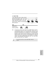
1.3 3 1-2 점퍼 CMOS 초기화 (CLRCMOS1, 3 2 33 세팅 CMOS 삭제 참고 : CLRCMOS1 CMOS 15 CLRCMOS1 의 핀 2 와 핀 3 을 5 BIOS CMOS BIOS CMOS CMOS CMOS 1394 GUID, MAC Clear CMOS Switch는 Clear CMOS 한국어 181 ASRock X79 Extreme6/GB / X79 Extreme6 Motherboard
1.3 3 1-2 점퍼 CMOS 초기화 (CLRCMOS1, 3 2 33 세팅 CMOS 삭제 참고 : CLRCMOS1 CMOS 15 CLRCMOS1 의 핀 2 와 핀 3 을 5 BIOS CMOS BIOS CMOS CMOS CMOS 1394 GUID, MAC Clear CMOS Switch는 Clear CMOS 한국어 181 ASRock X79 Extreme6/GB / X79 Extreme6 Motherboard

Quick Installation Guide
Page 232
1.3 3 1 和針腳 2 CMOS (CLRCMOS1, 3 2 頁第 33 項 ) 設定 默認設置 清除 CMOS 註: C L R C M O S1 C M O S 15 CLRCMOS1 的 pin2 及 pin3 短路 5 BIOS CMOS BIOS CMOS CMOS C M O S 1394 GUID 及 MAC Clear CMOS Clear CMOS 繁體中文 232 ASRock X79 Extreme6/GB / X79 Extreme6 Motherboard
1.3 3 1 和針腳 2 CMOS (CLRCMOS1, 3 2 頁第 33 項 ) 設定 默認設置 清除 CMOS 註: C L R C M O S1 C M O S 15 CLRCMOS1 的 pin2 及 pin3 短路 5 BIOS CMOS BIOS CMOS CMOS C M O S 1394 GUID 及 MAC Clear CMOS Clear CMOS 繁體中文 232 ASRock X79 Extreme6/GB / X79 Extreme6 Motherboard

