User Manual
Page 7
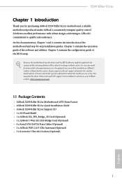
... the motherboard and step-by-step installation guides. If you are using. ASRock website http://www.asrock.com. 1.1 Package Contents • ASRock X299 Killer SLI/ac Motherboard (ATX Form Factor) • ASRock X299 Killer SLI/ac Quick Installation Guide • ASRock X299 Killer SLI/ac Support CD • 1 x I/O Panel Shield • 1 x ASRock SLI_HB_Bridge_2S Card (Optional) • 1 x ASRock 3-Way SLI-2S1S Bridge Card (Optional) • 4 x Serial ATA (SATA) Data Cables (Optional) •...
... the motherboard and step-by-step installation guides. If you are using. ASRock website http://www.asrock.com. 1.1 Package Contents • ASRock X299 Killer SLI/ac Motherboard (ATX Form Factor) • ASRock X299 Killer SLI/ac Quick Installation Guide • ASRock X299 Killer SLI/ac Support CD • 1 x I/O Panel Shield • 1 x ASRock SLI_HB_Bridge_2S Card (Optional) • 1 x ASRock 3-Way SLI-2S1S Bridge Card (Optional) • 4 x Serial ATA (SATA) Data Cables (Optional) •...

User Manual
Page 8
...ATX Form Factor • 8 Layer PCB • Supports Intel® CoreTM X-Series Processor Family for the LGA 2066 Socket • Digi Power design • 11 Power Phase design • Supports Intel® Turbo Boost Max Technology 3.0 * Please note that the 4-Core processors only support Intel® Turbo Boost Technology 2.0. • Supports ASRock... Hyper BCLK Engine III Chipset • Intel® X299 Memory • Quad Channel DDR4 Memory Technology • 8 x DDR4 DIMM Slots &#...
...ATX Form Factor • 8 Layer PCB • Supports Intel® CoreTM X-Series Processor Family for the LGA 2066 Socket • Digi Power design • 11 Power Phase design • Supports Intel® Turbo Boost Max Technology 3.0 * Please note that the 4-Core processors only support Intel® Turbo Boost Technology 2.0. • Supports ASRock... Hyper BCLK Engine III Chipset • Intel® X299 Memory • Quad Channel DDR4 Memory Technology • 8 x DDR4 DIMM Slots &#...

User Manual
Page 11
... maximum 1.5A (18W) fan power. * CHA_FAN1 and CHA_FAN2 can auto detect if 3-pin or 4-pin fan is in use. • 1 x 24 pin ATX Power Connector (Hi-Density Power Con- X299 Killer SLI/ac Connector • 1 x Virtual RAID On CPU Header • 1 x TPM Header • 1 x Power LED and Speaker Header • 2 x RGB LED Headers * Support up...
... maximum 1.5A (18W) fan power. * CHA_FAN1 and CHA_FAN2 can auto detect if 3-pin or 4-pin fan is in use. • 1 x 24 pin ATX Power Connector (Hi-Density Power Con- X299 Killer SLI/ac Connector • 1 x Virtual RAID On CPU Header • 1 x TPM Header • 1 x Power LED and Speaker Header • 2 x RGB LED Headers * Support up...

User Manual
Page 14
... Connector (CPU_OPT/W_PUMP1) 5 2 x 288-pin DDR4 DIMM Slots (DDR4_C2, DDR4_D2) 6 2 x 288-pin DDR4 DIMM Slots (DDR4_C1, DDR4_D1) 7 CPU Fan Connector (CPU_FAN1) 8 RGB LED Header (RGB_LED2) 9 ATX Power Connector (ATXPWR1) 10 Virtual RAID On CPU Header (VROC1) 11 USB 3.0 Header (USB3_5_6) 12 SATA3 Connectors (SATA3_0_1) 13 SATA3 Connectors (SATA3_2_3) 14 SATA3 Connectors...
... Connector (CPU_OPT/W_PUMP1) 5 2 x 288-pin DDR4 DIMM Slots (DDR4_C2, DDR4_D2) 6 2 x 288-pin DDR4 DIMM Slots (DDR4_C1, DDR4_D1) 7 CPU Fan Connector (CPU_FAN1) 8 RGB LED Header (RGB_LED2) 9 ATX Power Connector (ATXPWR1) 10 Virtual RAID On CPU Header (VROC1) 11 USB 3.0 Header (USB3_5_6) 12 SATA3 Connectors (SATA3_0_1) 13 SATA3 Connectors (SATA3_2_3) 14 SATA3 Connectors...
User Manual
Page 19
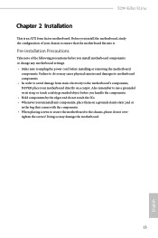
... note of your chassis to ensure that comes with the components. • When placing screws to secure the motherboard to do not overtighten the screws! X299 Killer SLI/ac Chapter 2 Installation This is an ATX form factor motherboard.
... note of your chassis to ensure that comes with the components. • When placing screws to secure the motherboard to do not overtighten the screws! X299 Killer SLI/ac Chapter 2 Installation This is an ATX form factor motherboard.

User Manual
Page 32
CPU Fan Connector (4-pin CPU_FAN1) (see p.7, No. 9) 12 24 1 13 This motherboard provides a 24-pin ATX power connector. ATX Power Connector (24-pin ATXPWR1) (see p.7, No. 7) FAN_SPEED_CONTROL CPU_FAN_SPEED FAN_VOLTAGE GND 1 2 34 This motherboard provides a 4-Pin CPU fan (Quiet Fan) connector. (4-pin CHA_FAN2) (see p.7, No. ... CPU_OPT/W_ PUMP) (see p.7, No. 19) 4 3 21 FAN_SPEED_CONTROL CHA_FAN_SPEED FAN_VOLTAGE GND This motherboard provides two 4-Pin water cooling chassis fan connectors. To use a 20-pin ATX power supply, please plug it to Pin 1-3.
CPU Fan Connector (4-pin CPU_FAN1) (see p.7, No. 9) 12 24 1 13 This motherboard provides a 24-pin ATX power connector. ATX Power Connector (24-pin ATXPWR1) (see p.7, No. 7) FAN_SPEED_CONTROL CPU_FAN_SPEED FAN_VOLTAGE GND 1 2 34 This motherboard provides a 4-Pin CPU fan (Quiet Fan) connector. (4-pin CHA_FAN2) (see p.7, No. ... CPU_OPT/W_ PUMP) (see p.7, No. 19) 4 3 21 FAN_SPEED_CONTROL CHA_FAN_SPEED FAN_VOLTAGE GND This motherboard provides two 4-Pin water cooling chassis fan connectors. To use a 20-pin ATX power supply, please plug it to Pin 1-3.

User Manual
Page 33
... also helps enhance network security, protects digital identities, and ensures platform integrity. English 27 To use a 4-pin ATX power supply, please plug it along Pin 1 and Pin 5. X299 Killer SLI/ac ATX 12V Power Connector (8-pin ATX12V1) (see p.7, No. 3) 8 5 4 1 TPM Header (17-pin TPMS1...LAD3 +3V LAD0 +3VS B GN D GN D SMB_CLK_MAIN SMB_DATA_MAIN LAD2 LAD1 GN D S_PWRDWN # SERIRQ # GND This motherboard provides an 8-pin ATX 12V power connector. Please connect a Thunderbolt™ add-in the wrong orientation; These two RGB headers are used to connect RGB LED extension cable...
... also helps enhance network security, protects digital identities, and ensures platform integrity. English 27 To use a 4-pin ATX power supply, please plug it along Pin 1 and Pin 5. X299 Killer SLI/ac ATX 12V Power Connector (8-pin ATX12V1) (see p.7, No. 3) 8 5 4 1 TPM Header (17-pin TPMS1...LAD3 +3V LAD0 +3VS B GN D GN D SMB_CLK_MAIN SMB_DATA_MAIN LAD2 LAD1 GN D S_PWRDWN # SERIRQ # GND This motherboard provides an 8-pin ATX 12V power connector. Please connect a Thunderbolt™ add-in the wrong orientation; These two RGB headers are used to connect RGB LED extension cable...

Quick Installation Guide
Page 4
... Connector (CPU_OPT/W_PUMP1) 5 2 x 288-pin DDR4 DIMM Slots (DDR4_C2, DDR4_D2) 6 2 x 288-pin DDR4 DIMM Slots (DDR4_C1, DDR4_D1) 7 CPU Fan Connector (CPU_FAN1) 8 RGB LED Header (RGB_LED2) 9 ATX Power Connector (ATXPWR1) 10 Virtual RAID On CPU Header (VROC1) 11 USB 3.0 Header (USB3_5_6) 12 SATA3 Connectors (SATA3_0_1) 13 SATA3 Connectors (SATA3_2_3) 14 SATA3 Connectors...
... Connector (CPU_OPT/W_PUMP1) 5 2 x 288-pin DDR4 DIMM Slots (DDR4_C2, DDR4_D2) 6 2 x 288-pin DDR4 DIMM Slots (DDR4_C1, DDR4_D1) 7 CPU Fan Connector (CPU_FAN1) 8 RGB LED Header (RGB_LED2) 9 ATX Power Connector (ATXPWR1) 10 Virtual RAID On CPU Header (VROC1) 11 USB 3.0 Header (USB3_5_6) 12 SATA3 Connectors (SATA3_0_1) 13 SATA3 Connectors (SATA3_2_3) 14 SATA3 Connectors...
Quick Installation Guide
Page 7
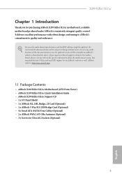
...; ASRock X299 Killer SLI/ac Motherboard (ATX Form Factor) • ASRock X299 Killer SLI/ac Quick Installation Guide • ASRock X299 Killer SLI/ac Support CD • 1 x I/O Panel Shield • 1 x ASRock SLI_HB_Bridge_2S Card (Optional) • 1 x ASRock 3-Way SLI-2S1S Bridge Card (Optional) • 4 x Serial ATA (SATA) Data Cables (Optional) • 2 x ASRock WiFi 2.4/5 GHz Antennas (Optional) • 3 x Screws for purchasing ASRock X299 Killer SLI/ac motherboard, a reliable motherboard produced under ASRock's consistently stringent quality control. X299 Killer SLI/ac Chapter...
...; ASRock X299 Killer SLI/ac Motherboard (ATX Form Factor) • ASRock X299 Killer SLI/ac Quick Installation Guide • ASRock X299 Killer SLI/ac Support CD • 1 x I/O Panel Shield • 1 x ASRock SLI_HB_Bridge_2S Card (Optional) • 1 x ASRock 3-Way SLI-2S1S Bridge Card (Optional) • 4 x Serial ATA (SATA) Data Cables (Optional) • 2 x ASRock WiFi 2.4/5 GHz Antennas (Optional) • 3 x Screws for purchasing ASRock X299 Killer SLI/ac motherboard, a reliable motherboard produced under ASRock's consistently stringent quality control. X299 Killer SLI/ac Chapter...

Quick Installation Guide
Page 8
...ATX Form Factor • 8 Layer PCB • Supports Intel® CoreTM X-Series Processor Family for the LGA 2066 Socket • Digi Power design • 11 Power Phase design • Supports Intel® Turbo Boost Max Technology 3.0 * Please note that the 4-Core processors only support Intel® Turbo Boost Technology 2.0. • Supports ASRock... Hyper BCLK Engine III Chipset • Intel® X299 Memory • Quad Channel DDR4 Memory Technology • 8 x DDR4 DIMM Slots &#...
...ATX Form Factor • 8 Layer PCB • Supports Intel® CoreTM X-Series Processor Family for the LGA 2066 Socket • Digi Power design • 11 Power Phase design • Supports Intel® Turbo Boost Max Technology 3.0 * Please note that the 4-Core processors only support Intel® Turbo Boost Technology 2.0. • Supports ASRock... Hyper BCLK Engine III Chipset • Intel® X299 Memory • Quad Channel DDR4 Memory Technology • 8 x DDR4 DIMM Slots &#...

Quick Installation Guide
Page 11
X299 Killer SLI/ac BIOS Feature • 1 x CPU Fan Connector (4-pin) * The CPU Fan Connector supports the CPU fan of maximum 1A (12W) fan power. • 1 x CPU Optional/Water ... cooler fan of maximum 1.5A (18W) fan power. * CHA_FAN1 and CHA_FAN2 can auto detect if 3-pin or 4-pin fan is in use. • 1 x 24 pin ATX Power Connector (Hi-Density Power Con- trol) • 1 x Chassis Optional/Water Pump Fan Connector (4-pin) * The Chassis Optional/Water Pump Fan supports the water cooler...
X299 Killer SLI/ac BIOS Feature • 1 x CPU Fan Connector (4-pin) * The CPU Fan Connector supports the CPU fan of maximum 1A (12W) fan power. • 1 x CPU Optional/Water ... cooler fan of maximum 1.5A (18W) fan power. * CHA_FAN1 and CHA_FAN2 can auto detect if 3-pin or 4-pin fan is in use. • 1 x 24 pin ATX Power Connector (Hi-Density Power Con- trol) • 1 x Chassis Optional/Water Pump Fan Connector (4-pin) * The Chassis Optional/Water Pump Fan supports the water cooler...

Quick Installation Guide
Page 15
Before you install motherboard components or change any components, place them on a carpet. X299 Killer SLI/ac Chapter 2 Installation This is an ATX form factor motherboard. Pre-installation Precautions Take note of your motherboard directly on a grounded anti-static pad or in the bag that the motherboard fits ...
Before you install motherboard components or change any components, place them on a carpet. X299 Killer SLI/ac Chapter 2 Installation This is an ATX form factor motherboard. Pre-installation Precautions Take note of your motherboard directly on a grounded anti-static pad or in the bag that the motherboard fits ...

Quick Installation Guide
Page 28
CPU Fan Connector (4-pin CPU_FAN1) (see p.1, No. 9) 12 24 1 13 This motherboard provides a 24-pin ATX power connector. ATX Power Connector (24-pin ATXPWR1) (see p.1, No. 7) FAN_SPEED_CONTROL CPU_FAN_SPEED FAN_VOLTAGE GND 1 2 34 This motherboard provides a 4-Pin CPU fan (Quiet Fan) connector. ... to Pin 1-3. If you plan to connect a 3-Pin chassis water cooler fan, please connect it along Pin 1 and Pin 13. To use a 20-pin ATX power supply, please plug it to Pin 1-3. If you plan to connect a 3-Pin CPU fan, please connect it to Pin 1-3. (4-pin CHA_FAN2) (see p.1,...
CPU Fan Connector (4-pin CPU_FAN1) (see p.1, No. 9) 12 24 1 13 This motherboard provides a 24-pin ATX power connector. ATX Power Connector (24-pin ATXPWR1) (see p.1, No. 7) FAN_SPEED_CONTROL CPU_FAN_SPEED FAN_VOLTAGE GND 1 2 34 This motherboard provides a 4-Pin CPU fan (Quiet Fan) connector. ... to Pin 1-3. If you plan to connect a 3-Pin chassis water cooler fan, please connect it along Pin 1 and Pin 13. To use a 20-pin ATX power supply, please plug it to Pin 1-3. If you plan to connect a 3-Pin CPU fan, please connect it to Pin 1-3. (4-pin CHA_FAN2) (see p.1,...

Quick Installation Guide
Page 29
Please connect a Thunderbolt™ add-in the wrong orientation; X299 Killer SLI/ac ATX 12V Power Connector (8-pin ATX12V1) (see p.1, No. 3) 8 5 4 1 TPM Header (17-pin TPMS1) (see p.1, No. 23) 1 Thunderbolt AIC Connector (5-pin TB1) (see... G R B 1 12V G R B PCICLK FRAM E PCIRST # LAD3 +3V LAD0 +3VS B GN D GN D SMB_CLK_MAIN SMB_DATA_MAIN LAD2 LAD1 GN D S_PWRDWN # SERIRQ # GND This motherboard provides an 8-pin ATX 12V power connector. This connector supports Trusted Platform Module (TPM) system, which allows users to this connector via the GPIO cable. otherwise, the cable may...
Please connect a Thunderbolt™ add-in the wrong orientation; X299 Killer SLI/ac ATX 12V Power Connector (8-pin ATX12V1) (see p.1, No. 3) 8 5 4 1 TPM Header (17-pin TPMS1) (see p.1, No. 23) 1 Thunderbolt AIC Connector (5-pin TB1) (see... G R B 1 12V G R B PCICLK FRAM E PCIRST # LAD3 +3V LAD0 +3VS B GN D GN D SMB_CLK_MAIN SMB_DATA_MAIN LAD2 LAD1 GN D S_PWRDWN # SERIRQ # GND This motherboard provides an 8-pin ATX 12V power connector. This connector supports Trusted Platform Module (TPM) system, which allows users to this connector via the GPIO cable. otherwise, the cable may...

Quick Installation Guide
Page 137
X299 Killer SLI/ac 한국어 1.2 규격 플랫폼 • ATX 8 레이어 PCB CPU • LGA 2066 소켓용 Intel® CoreTM X • Digi 11 Intel® Turbo Boost Max Technology 3.0 지원 * 4 Intel® Turbo Boost Technology 2.0 ASRock Hyper BCLK Engine III 지원 칩세트 • Intel®...
X299 Killer SLI/ac 한국어 1.2 규격 플랫폼 • ATX 8 레이어 PCB CPU • LGA 2066 소켓용 Intel® CoreTM X • Digi 11 Intel® Turbo Boost Max Technology 3.0 지원 * 4 Intel® Turbo Boost Technology 2.0 ASRock Hyper BCLK Engine III 지원 칩세트 • Intel®...

Quick Installation Guide
Page 154
... (12W CPU 1 x CPU 4 ϐϯʣ * CPU 1.5A (18W 2 x 4 1 x 4 1.5A (18W CPU_FAN1 ͓Αͼ CHA_FAN2 3 ϐϯ·ͨ 4 1 x 24 ϐϯ ATX λʔʣ • 1 x 8 ϐϯ 12V 1 x 15 1 x Thunderbolt AIC ίωΫλ (5 ϐϯ ) • 3 x USB 2.0 ϔομʔʢ6 ͭͷ...
... (12W CPU 1 x CPU 4 ϐϯʣ * CPU 1.5A (18W 2 x 4 1 x 4 1.5A (18W CPU_FAN1 ͓Αͼ CHA_FAN2 3 ϐϯ·ͨ 4 1 x 24 ϐϯ ATX λʔʣ • 1 x 8 ϐϯ 12V 1 x 15 1 x Thunderbolt AIC ίωΫλ (5 ϐϯ ) • 3 x USB 2.0 ϔομʔʢ6 ͭͷ...

Quick Installation Guide
Page 168
...; 1 x CPU 4 针 ) * CPU 1A (12W) 功率的 CPU 1 x CPU 4 针 ) * CPU 1.5A (18W 2 x 4 1 x 4 1.5A (18W CHA_FAN1 和 CHA_FAN2 3 针脚或 4 • 1 x 24 针 ATX 1 x 8 针 12V 1 x 15 1 x Thunderbolt AIC 接口 (5 针 ) • 3 x USB 2.0 6 个 USB 2.0 ESD 1 x USB 3.0 2 个 USB 3.0 ESD 保护) BIOS • 2 x AMI UEFI Legal...
...; 1 x CPU 4 针 ) * CPU 1A (12W) 功率的 CPU 1 x CPU 4 针 ) * CPU 1.5A (18W 2 x 4 1 x 4 1.5A (18W CHA_FAN1 和 CHA_FAN2 3 针脚或 4 • 1 x 24 针 ATX 1 x 8 针 12V 1 x 15 1 x Thunderbolt AIC 接口 (5 针 ) • 3 x USB 2.0 6 个 USB 2.0 ESD 1 x USB 3.0 2 个 USB 3.0 ESD 保护) BIOS • 2 x AMI UEFI Legal...

Quick Installation Guide
Page 183
繁體中文 X299 Killer SLI/ac 接頭 • 1 x Virtual RAID On CPU 排針 • 1 x TPM 排針 • 1 x 電源 LED 2 x RGB LED 12V/... 1A (12W CPU 1 x CPU 4-pin) * CPU 1.5A (18W • 2 x 4-pin 1 x 4-pin 1.5A (18W * 如果 3-pin 或 4-pin CHA_FAN1 和 CHA_FAN2。 • 1 x 24 pin ATX 1 x 8 pin 12V 1 x 15 1 x Thunderbolt AIC 接頭 (5-pin) • 3 x USB 2.0 6 個 USB 2.0 保護) • 1 x USB 3.0 2 個 USB 3.0 BIOS 功能...
繁體中文 X299 Killer SLI/ac 接頭 • 1 x Virtual RAID On CPU 排針 • 1 x TPM 排針 • 1 x 電源 LED 2 x RGB LED 12V/... 1A (12W CPU 1 x CPU 4-pin) * CPU 1.5A (18W • 2 x 4-pin 1 x 4-pin 1.5A (18W * 如果 3-pin 或 4-pin CHA_FAN1 和 CHA_FAN2。 • 1 x 24 pin ATX 1 x 8 pin 12V 1 x 15 1 x Thunderbolt AIC 接頭 (5-pin) • 3 x USB 2.0 6 個 USB 2.0 保護) • 1 x USB 3.0 2 個 USB 3.0 BIOS 功能...

Quick Installation Guide
Page 190
... 8 (8-pin ATX12V1) 1 3) 4 TPM 排針 (17-pin TPMS1 1 23) 1 GN D SMB_CLK_MAIN SMB_DATA_MAIN LAD2 LAD1 GN D S_PWRDWN # SERIRQ # GND 5 8-pin ATX 12V 1 要使用 4-pin ATX 電源 Pin 1 及 Pin 5。 TPM TPM PCICLK FRAM E PCIRST # LAD3 +3V LAD0 +3VS B GN D Thunderbolt AIC 接頭 1 (5-pin TB1) 1 24) 請透&#...
... 8 (8-pin ATX12V1) 1 3) 4 TPM 排針 (17-pin TPMS1 1 23) 1 GN D SMB_CLK_MAIN SMB_DATA_MAIN LAD2 LAD1 GN D S_PWRDWN # SERIRQ # GND 5 8-pin ATX 12V 1 要使用 4-pin ATX 電源 Pin 1 及 Pin 5。 TPM TPM PCICLK FRAM E PCIRST # LAD3 +3V LAD0 +3VS B GN D Thunderbolt AIC 接頭 1 (5-pin TB1) 1 24) 請透&#...
