
User Manual
Page 4
...Package Contents 1 1.2 Specifications 2 1.3 Motherboard Layout 7 1.4 I/O Panel 9 Chapter 2 Installation 13 2.1 Installing the CPU 14 2.2 Installing the CPU Fan and Heatsink 17 2.3 Installation of Memory Modules (DIMM) 18 2.4 Expansion Slots (PCI Express Slots) 20 2.5 Jumpers Setup 22 2.6 Onboard Headers and Connectors 23 2.7 Smart Switches 29 2.8 SLITM , 3-Way SLITMand Quad SLITM Operation Guide 30 2.8.1 Installing Two SLITM-Ready Graphics Cards 30 2.8.2 Installing Three SLITM-Ready Graphics Cards 32 2.8.3 Driver Installation and Setup 34 2.9 CrossFireXTM, 3-Way...
...Package Contents 1 1.2 Specifications 2 1.3 Motherboard Layout 7 1.4 I/O Panel 9 Chapter 2 Installation 13 2.1 Installing the CPU 14 2.2 Installing the CPU Fan and Heatsink 17 2.3 Installation of Memory Modules (DIMM) 18 2.4 Expansion Slots (PCI Express Slots) 20 2.5 Jumpers Setup 22 2.6 Onboard Headers and Connectors 23 2.7 Smart Switches 29 2.8 SLITM , 3-Way SLITMand Quad SLITM Operation Guide 30 2.8.1 Installing Two SLITM-Ready Graphics Cards 30 2.8.2 Installing Three SLITM-Ready Graphics Cards 32 2.8.3 Driver Installation and Setup 34 2.9 CrossFireXTM, 3-Way...
User Manual
Page 7
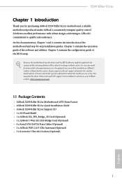
...our website for specific information about the model you are using. If you require technical support related to quality and endurance. ASRock website http://www.asrock.com. 1.1 Package Contents • ASRock X299 Killer SLI/ac Motherboard (ATX Form Factor) • ASRock X299 Killer SLI/ac Quick Installation Guide • ASRock X299 Killer SLI/ac Support CD • 1 x I/O Panel Shield • 1 x ASRock SLI_HB_Bridge_2S Card (Optional) • 1 x ASRock 3-Way SLI-2S1S Bridge Card (Optional) • 4 x Serial ATA (SATA) Data Cables (Optional) • 2 x ASRock WiFi 2.4/5 GHz Antennas...
...our website for specific information about the model you are using. If you require technical support related to quality and endurance. ASRock website http://www.asrock.com. 1.1 Package Contents • ASRock X299 Killer SLI/ac Motherboard (ATX Form Factor) • ASRock X299 Killer SLI/ac Quick Installation Guide • ASRock X299 Killer SLI/ac Support CD • 1 x I/O Panel Shield • 1 x ASRock SLI_HB_Bridge_2S Card (Optional) • 1 x ASRock 3-Way SLI-2S1S Bridge Card (Optional) • 4 x Serial ATA (SATA) Data Cables (Optional) • 2 x ASRock WiFi 2.4/5 GHz Antennas...

User Manual
Page 9
... Module (Free Bundle) • Supports IEEE 802.11a/b/g/n/ac • Supports Dual-Band (2.4/5 GHz) • Supports high speed wireless connections up to 433Mbps • Supports Bluetooth 4.2 / 3.0 + High speed class II 3 English Nichicon Fine Gold Series Audio Caps - 120dB SNR DAC with Content Protection (Realtek ALC1220 Audio Codec) • Premium Blu-ray Audio support • Supports Surge Protection • Supports Purity SoundTM 4 - X299 Killer SLI/ac ** If PCIE4 slot is occupied, M2_2 slot will support M.2 PCI Express module up...
... Module (Free Bundle) • Supports IEEE 802.11a/b/g/n/ac • Supports Dual-Band (2.4/5 GHz) • Supports high speed wireless connections up to 433Mbps • Supports Bluetooth 4.2 / 3.0 + High speed class II 3 English Nichicon Fine Gold Series Audio Caps - 120dB SNR DAC with Content Protection (Realtek ALC1220 Audio Codec) • Premium Blu-ray Audio support • Supports Surge Protection • Supports Purity SoundTM 4 - X299 Killer SLI/ac ** If PCIE4 slot is occupied, M2_2 slot will support M.2 PCI Express module up...

User Manual
Page 11
...X299 Killer SLI/ac Connector • 1 x Virtual RAID On CPU Header • 1 x TPM Header • 1 x Power LED and Speaker Header • 2 x RGB LED Headers * Support up events • SMBIOS 3.0 Support • CPU, DRAM, VPPM, VTTM, PCH 1.0V, VCCMPHY, VCCIO, VCCST, VCCSA, VCCSFR, VCCPLL, CLK VDD, PEGRCOMP Voltage Multi-adjustment English 5 tor) • 1 x Thunderbolt AIC Connector (5-pin) • 3 x USB 2.0 Headers (Support 6 USB 2.0 ports) (Supports ESD Protection) • 1 x USB 3.0 Headers (Support 2 USB 3.0 ports) (Supports ESD Protection) BIOS Feature • 2 x AMI UEFI...
...X299 Killer SLI/ac Connector • 1 x Virtual RAID On CPU Header • 1 x TPM Header • 1 x Power LED and Speaker Header • 2 x RGB LED Headers * Support up events • SMBIOS 3.0 Support • CPU, DRAM, VPPM, VTTM, PCH 1.0V, VCCMPHY, VCCIO, VCCST, VCCSA, VCCSFR, VCCPLL, CLK VDD, PEGRCOMP Voltage Multi-adjustment English 5 tor) • 1 x Thunderbolt AIC Connector (5-pin) • 3 x USB 2.0 Headers (Support 6 USB 2.0 ports) (Supports ESD Protection) • 1 x USB 3.0 Headers (Support 2 USB 3.0 ports) (Supports ESD Protection) BIOS Feature • 2 x AMI UEFI...

User Manual
Page 13
1.3 Motherboard Layout X299 Killer SLI/ac 12 3 4 56 7 USB 2.0 T: USB3 B: USB4 PS2 Keyboard /Mouse M2_WIFI_1 CLRC BTN1 USB 3.0 T: USB3 B: USB4 USB 3.0 T: USB1 B: USB2 USB 2.0 T: USB1 Top: RJ-45 B: USB2 USB 3.1 T: USB31_TA_1 B: USB31_TC_1 Top: Central/Bass LINE IN Center: REAR SPK Bottom: Optical SPDIF Top: Center: FRONT Bottom: MIC IN LAN 28 LAN DDR4_B1 (64 bit, 288-pin module) DDR4_B2 (64 bit, 288-pin module) DDR4_A1 (64 bit, 288-pin module) DDR4_A2 (64...
1.3 Motherboard Layout X299 Killer SLI/ac 12 3 4 56 7 USB 2.0 T: USB3 B: USB4 PS2 Keyboard /Mouse M2_WIFI_1 CLRC BTN1 USB 3.0 T: USB3 B: USB4 USB 3.0 T: USB1 B: USB2 USB 2.0 T: USB1 Top: RJ-45 B: USB2 USB 3.1 T: USB31_TA_1 B: USB31_TC_1 Top: Central/Bass LINE IN Center: REAR SPK Bottom: Optical SPDIF Top: Center: FRONT Bottom: MIC IN LAN 28 LAN DDR4_B1 (64 bit, 288-pin module) DDR4_B2 (64 bit, 288-pin module) DDR4_A1 (64 bit, 288-pin module) DDR4_A2 (64...

User Manual
Page 14
...) 10 Virtual RAID On CPU Header (VROC1) 11 USB 3.0 Header (USB3_5_6) 12 SATA3 Connectors (SATA3_0_1) 13 SATA3 Connectors (SATA3_2_3) 14 SATA3 Connectors (SATA3_4_5) 15 SATA3 Connectors (SATA3_6_7) 16 Power LED and Speaker Header (SPK_PLED1) 17 Chassis Fan Connector (CHA_FAN1) 18 System Panel Header (PANEL1) 19 Chassis Fan / Waterpump Fan Connector (CHA_FAN3/W_PUMP2) 20 USB 2.0 Header (USB_9_10) 21 USB 2.0 Header (USB_7_8) 22 USB 2.0 Header (USB_5_6) 23 TPM Header (TPMS1) 24 Thunderbolt AIC Header (TB1) 25 RGB LED Header (RGB_LED1) 26 Clear CMOS Jumper (CLRMOS1) 27 Front Panel Audio Header...
...) 10 Virtual RAID On CPU Header (VROC1) 11 USB 3.0 Header (USB3_5_6) 12 SATA3 Connectors (SATA3_0_1) 13 SATA3 Connectors (SATA3_2_3) 14 SATA3 Connectors (SATA3_4_5) 15 SATA3 Connectors (SATA3_6_7) 16 Power LED and Speaker Header (SPK_PLED1) 17 Chassis Fan Connector (CHA_FAN1) 18 System Panel Header (PANEL1) 19 Chassis Fan / Waterpump Fan Connector (CHA_FAN3/W_PUMP2) 20 USB 2.0 Header (USB_9_10) 21 USB 2.0 Header (USB_7_8) 22 USB 2.0 Header (USB_5_6) 23 TPM Header (TPMS1) 24 Thunderbolt AIC Header (TB1) 25 RGB LED Header (RGB_LED1) 26 Clear CMOS Jumper (CLRMOS1) 27 Front Panel Audio Header...

User Manual
Page 15
... USB 3.0 Ports (USB3_1_2) 13 USB 3.0 Ports (USB3_3_4) 14 Clear CMOS Switch 15 Antenna Ports 16 PS/2 Mouse/Keyboard Port (PS2_KB1) * There are two LEDs on each LAN port. Please refer to the table below for the LAN port LED indications. Description 1 USB 2.0 Port (USB_3_4) 2 LAN RJ-45 Port (Intel® I219V)* 3 Central / Bass (Orange) 4 Rear Speaker (Black) 5 Line In (Light Blue) 6 Front Speaker (Lime)** 7 Microphone (Pink) 8 Optical SPDIF Out Port 12 11 9 87 10 No. 1.4 I/O Panel 1 X299 Killer SLI/ac...
... USB 3.0 Ports (USB3_1_2) 13 USB 3.0 Ports (USB3_3_4) 14 Clear CMOS Switch 15 Antenna Ports 16 PS/2 Mouse/Keyboard Port (PS2_KB1) * There are two LEDs on each LAN port. Please refer to the table below for the LAN port LED indications. Description 1 USB 2.0 Port (USB_3_4) 2 LAN RJ-45 Port (Intel® I219V)* 3 Central / Bass (Orange) 4 Rear Speaker (Black) 5 Line In (Light Blue) 6 Front Speaker (Lime)** 7 Microphone (Pink) 8 Optical SPDIF Out Port 12 11 9 87 10 No. 1.4 I/O Panel 1 X299 Killer SLI/ac...
User Manual
Page 17
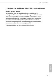
....0 standard features Smart Ready technology that offers support for PCs. * The transmission speed may vary according to support WiFi + BT. BT 4.0 also includes Low Energy Technology and ensures extraordinary low power consumption for WiFi 802.11 a/b/ g/n/ac connectivity standards and Bluetooth v4.0. X299 Killer SLI/ac 1.5 WiFi-802.11ac Module and ASRock WiFi 2.4/5 GHz Antenna WiFi-802.11ac + BT Module This motherboard comes with an...
....0 standard features Smart Ready technology that offers support for PCs. * The transmission speed may vary according to support WiFi + BT. BT 4.0 also includes Low Energy Technology and ensures extraordinary low power consumption for WiFi 802.11 a/b/ g/n/ac connectivity standards and Bluetooth v4.0. X299 Killer SLI/ac 1.5 WiFi-802.11ac Module and ASRock WiFi 2.4/5 GHz Antenna WiFi-802.11ac + BT Module This motherboard comes with an...
User Manual
Page 19
... unplug the power cord before you uninstall any components, place them on a carpet. Pre-installation Precautions Take note of your chassis to the motherboard's components, NEVER place your motherboard directly on a grounded anti-static pad or in the bag that the motherboard fits into it. X299 Killer SLI/ac Chapter 2 Installation This is an ATX form factor motherboard. Also remember to use a grounded wrist...
... unplug the power cord before you uninstall any components, place them on a carpet. Pre-installation Precautions Take note of your chassis to the motherboard's components, NEVER place your motherboard directly on a grounded anti-static pad or in the bag that the motherboard fits into it. X299 Killer SLI/ac Chapter 2 Installation This is an ATX form factor motherboard. Also remember to use a grounded wrist...

User Manual
Page 41
... CrossFire Bridge Step 2 Connect two graphics cards by installing a CrossFire Bridge on the CrossFire Bridge Interconnects on the slots. Make sure that your system requires. Please refer to the AMD's website for detailed installation guide. 2.9.1 Installing Two CrossFireXTM-Ready Graphics Cards Step 1 Insert one graphics card into PCIE1 slot and the other graphics card to AMD graphics card manuals for details. 4. It is only supported with CPU with this motherboard. X299 Killer SLI/ac 2.9 CrossFireXTM, 3-Way CrossFireXTM...
... CrossFire Bridge Step 2 Connect two graphics cards by installing a CrossFire Bridge on the CrossFire Bridge Interconnects on the slots. Make sure that your system requires. Please refer to the AMD's website for detailed installation guide. 2.9.1 Installing Two CrossFireXTM-Ready Graphics Cards Step 1 Insert one graphics card into PCIE1 slot and the other graphics card to AMD graphics card manuals for details. 4. It is only supported with CPU with this motherboard. X299 Killer SLI/ac 2.9 CrossFireXTM, 3-Way CrossFireXTM...

User Manual
Page 44
... boot into OS. Then select Enable AMD CrossFireX and click Apply. The Catalyst Uninstaller is an optional download. Please check AMD's website for AMD driver updates. English 38 Select the GPU number according to installation. 2.9.3 Driver Installation and Setup Step 1 Power on your computer. AMD Catalyst Control Center Step 4 Double-click the AMD Catalyst Control Center icon in your graphics card and click Apply. We recommend using this utility to uninstall any VGA drivers installed...
... boot into OS. Then select Enable AMD CrossFireX and click Apply. The Catalyst Uninstaller is an optional download. Please check AMD's website for AMD driver updates. English 38 Select the GPU number according to installation. 2.9.3 Driver Installation and Setup Step 1 Power on your computer. AMD Catalyst Control Center Step 4 Double-click the AMD Catalyst Control Center icon in your graphics card and click Apply. We recommend using this utility to uninstall any VGA drivers installed...

User Manual
Page 49
X299 Killer SLI/ac Chapter 3 Software and Utilities Operation 3.1 Installing Drivers The Support CD that comes with the motherboard contains necessary drivers and useful utilities that the motherboard supports. Running The Support CD To begin using the support CD, insert the CD into your system will be auto-detected and listed on a specific item then follow the order from top to bottom to your CD-ROM drive. The CD automatically displays the Main Menu if "AUTORUN" is...
X299 Killer SLI/ac Chapter 3 Software and Utilities Operation 3.1 Installing Drivers The Support CD that comes with the motherboard contains necessary drivers and useful utilities that the motherboard supports. Running The Support CD To begin using the support CD, insert the CD into your system will be auto-detected and listed on a specific item then follow the order from top to bottom to your CD-ROM drive. The CD automatically displays the Main Menu if "AUTORUN" is...

User Manual
Page 59
...; otherwise, the cable may cause damages to the RGB LED Headers (RGB_LED1, RGB_LED2) on the motherboard. 1 12V G RGB_LED2 R B RGB_LED1 1 12V G R B X299 Killer SLI/ac 1 B 12V G R 1. Failure to build their own stylish colorful lighting system. Please note that the RGB LED strips do so may be damaged. 2. The RGB LED header supports standard 5050 RGB LED strip (12V/G/R/B), with the package. 2. X299 Killer SLI/ac 3.4 ASRock RGB LED ASRock RGB LED is a lighting control utility specifically designed for...
...; otherwise, the cable may cause damages to the RGB LED Headers (RGB_LED1, RGB_LED2) on the motherboard. 1 12V G RGB_LED2 R B RGB_LED1 1 12V G R B X299 Killer SLI/ac 1 B 12V G R 1. Failure to build their own stylish colorful lighting system. Please note that the RGB LED strips do so may be damaged. 2. The RGB LED header supports standard 5050 RGB LED strip (12V/G/R/B), with the package. 2. X299 Killer SLI/ac 3.4 ASRock RGB LED ASRock RGB LED is a lighting control utility specifically designed for...

User Manual
Page 86
... PCH PCIE devices. PCIE ASPM Support This option enables/disables the ASPM support for PCIE5. If [Power Off] is selected, the system will remain off the LED in OS. Deep Sleep Configure deep sleep mode for enhanced PCI Express power saving in the ACPI S5 state. 80 English Restore on /off when the power recovers. Set to Auto to boot up when the power recovers. Front Panel Enable/disable front panel HD audio. Onboard LAN Enable or disable the onboard network interface controller. PCIE5 Link Speed...
... PCH PCIE devices. PCIE ASPM Support This option enables/disables the ASPM support for PCIE5. If [Power Off] is selected, the system will remain off the LED in OS. Deep Sleep Configure deep sleep mode for enhanced PCI Express power saving in the ACPI S5 state. 80 English Restore on /off when the power recovers. Set to Auto to boot up when the power recovers. Front Panel Enable/disable front panel HD audio. Onboard LAN Enable or disable the onboard network interface controller. PCIE5 Link Speed...
User Manual
Page 93
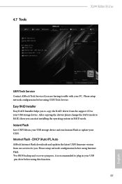
... update your USB pen drive before using this function. 87 English Instant Flash Save UEFI files in your USB storage device and run Instant Flash to plug in RAID mode. 4.7 Tools X299 Killer SLI/ac UEFI Tech Service Contact ASRock Tech Service if you are having trouble with your USB storage device. Internet Flash - Easy RAID Installer Easy RAID Installer helps you to copy the RAID driver from our servers for you. After copying the drivers please change the SATA mode to your PC. Please setup network configuration before using UEFI Tech Service...
... update your USB pen drive before using this function. 87 English Instant Flash Save UEFI files in your USB storage device and run Instant Flash to plug in RAID mode. 4.7 Tools X299 Killer SLI/ac UEFI Tech Service Contact ASRock Tech Service if you are having trouble with your USB storage device. Internet Flash - Easy RAID Installer Easy RAID Installer helps you to copy the RAID driver from our servers for you. After copying the drivers please change the SATA mode to your PC. Please setup network configuration before using UEFI Tech Service...

User Manual
Page 94
... download the UEFI firmware. 88 English UEFI Download Server Select a server to update the backup BIOS manually. Use "Secure Backup UEFI" to duplicate a working ROM image to configure internet connection settings for Internet Flash. Users may refer to the BIOS LEDs (BIOS_A_LED or BIOS_B_LED) to ensure normal system operation. This motherboard has two BIOS chips, an active BIOS (BIOS_A) and a backup BIOS (BIOS_B), which BIOS is corrupted or damaged, after several failed boot attempts, the backup BIOS...
... download the UEFI firmware. 88 English UEFI Download Server Select a server to update the backup BIOS manually. Use "Secure Backup UEFI" to duplicate a working ROM image to configure internet connection settings for Internet Flash. Users may refer to the BIOS LEDs (BIOS_A_LED or BIOS_B_LED) to ensure normal system operation. This motherboard has two BIOS chips, an active BIOS (BIOS_A) and a backup BIOS (BIOS_B), which BIOS is corrupted or damaged, after several failed boot attempts, the backup BIOS...

User Manual
Page 98
... Boot Use this option to enable or disable support for Windows 8.1 Secure Boot. Leave it blank and press enter to remove the password. Intel(R) Platform Trust Technology Enable/disable Intel PTT in the UEFI Setup Utility. Disable this item to use discrete TPM Module. 92 English Only the administrator has authority to change the settings in the UEFI Setup Utility. User Password Set or change the supervisor/user password for the system. You may set or change the password for the user account. 4.9 Security Screen...
... Boot Use this option to enable or disable support for Windows 8.1 Secure Boot. Leave it blank and press enter to remove the password. Intel(R) Platform Trust Technology Enable/disable Intel PTT in the UEFI Setup Utility. Disable this item to use discrete TPM Module. 92 English Only the administrator has authority to change the settings in the UEFI Setup Utility. User Password Set or change the supervisor/user password for the system. You may set or change the password for the user account. 4.9 Security Screen...

Quick Installation Guide
Page 4
...) 10 Virtual RAID On CPU Header (VROC1) 11 USB 3.0 Header (USB3_5_6) 12 SATA3 Connectors (SATA3_0_1) 13 SATA3 Connectors (SATA3_2_3) 14 SATA3 Connectors (SATA3_4_5) 15 SATA3 Connectors (SATA3_6_7) 16 Power LED and Speaker Header (SPK_PLED1) 17 Chassis Fan Connector (CHA_FAN1) 18 System Panel Header (PANEL1) 19 Chassis Fan / Waterpump Fan Connector (CHA_FAN3/W_PUMP2) 20 USB 2.0 Header (USB_9_10) 21 USB 2.0 Header (USB_7_8) 22 USB 2.0 Header (USB_5_6) 23 TPM Header (TPMS1) 24 Thunderbolt AIC Header (TB1) 25 RGB LED Header (RGB_LED1) 26 Clear CMOS Jumper (CLRMOS1) 27 Front Panel Audio Header...
...) 10 Virtual RAID On CPU Header (VROC1) 11 USB 3.0 Header (USB3_5_6) 12 SATA3 Connectors (SATA3_0_1) 13 SATA3 Connectors (SATA3_2_3) 14 SATA3 Connectors (SATA3_4_5) 15 SATA3 Connectors (SATA3_6_7) 16 Power LED and Speaker Header (SPK_PLED1) 17 Chassis Fan Connector (CHA_FAN1) 18 System Panel Header (PANEL1) 19 Chassis Fan / Waterpump Fan Connector (CHA_FAN3/W_PUMP2) 20 USB 2.0 Header (USB_9_10) 21 USB 2.0 Header (USB_7_8) 22 USB 2.0 Header (USB_5_6) 23 TPM Header (TPMS1) 24 Thunderbolt AIC Header (TB1) 25 RGB LED Header (RGB_LED1) 26 Clear CMOS Jumper (CLRMOS1) 27 Front Panel Audio Header...
Quick Installation Guide
Page 7
... SLI/ac Support CD • 1 x I/O Panel Shield • 1 x ASRock SLI_HB_Bridge_2S Card (Optional) • 1 x ASRock 3-Way SLI-2S1S Bridge Card (Optional) • 4 x Serial ATA (SATA) Data Cables (Optional) • 2 x ASRock WiFi 2.4/5 GHz Antennas (Optional) • 3 x Screws for purchasing ASRock X299 Killer SLI/ac motherboard, a reliable motherboard produced under ASRock's consistently stringent quality control. Because the motherboard specifications and the BIOS software might be updated, the content of this documentation will be subject to change without further notice. In case...
... SLI/ac Support CD • 1 x I/O Panel Shield • 1 x ASRock SLI_HB_Bridge_2S Card (Optional) • 1 x ASRock 3-Way SLI-2S1S Bridge Card (Optional) • 4 x Serial ATA (SATA) Data Cables (Optional) • 2 x ASRock WiFi 2.4/5 GHz Antennas (Optional) • 3 x Screws for purchasing ASRock X299 Killer SLI/ac motherboard, a reliable motherboard produced under ASRock's consistently stringent quality control. Because the motherboard specifications and the BIOS software might be updated, the content of this documentation will be subject to change without further notice. In case...

RAID Installation Guide
Page 7
... not available for instructions on your system, and press key to Advanced Storage Configuration and set RAID configuration. Press [Enter] to [RAID]. Go to enter BIOS setup utility. STEP 1: Setting the BIOS RAID Items After installing the hard disk drives, please set the necessary RAID items in your RAID configuration. Please note that this document for all models A. Plug in the BIOS before setting your USB flash drive into a USB port B. Boot your system. 7 STEP 4: Install Windows® 10 64-bit OS on how to set SATA Mode Selection to...
... not available for instructions on your system, and press key to Advanced Storage Configuration and set RAID configuration. Press [Enter] to [RAID]. Go to enter BIOS setup utility. STEP 1: Setting the BIOS RAID Items After installing the hard disk drives, please set the necessary RAID items in your RAID configuration. Please note that this document for all models A. Plug in the BIOS before setting your USB flash drive into a USB port B. Boot your system. 7 STEP 4: Install Windows® 10 64-bit OS on how to set SATA Mode Selection to...


