
User Manual
Page 8
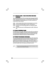
... SATAII connector directly. 10. Before you install the PC system. 9. Power Management for system usage under Microsoft® Windows® VistaTM 64-bit / VistaTM / XP 64-bit / XP SP1 or SP2 / 2000 SP4. 11. sponding memory support frequency. You can also connect SATA hard disk to perform over-clocking. This motherboard supports Dual Channel Memory Technology. CAUTION! 1. Due to read "Untied Overclocking Technology" on this motherboard offers stepless control, it will operate in overclocking mode. To...
... SATAII connector directly. 10. Before you install the PC system. 9. Power Management for system usage under Microsoft® Windows® VistaTM 64-bit / VistaTM / XP 64-bit / XP SP1 or SP2 / 2000 SP4. 11. sponding memory support frequency. You can also connect SATA hard disk to perform over-clocking. This motherboard supports Dual Channel Memory Technology. CAUTION! 1. Due to read "Untied Overclocking Technology" on this motherboard offers stepless control, it will operate in overclocking mode. To...
User Manual
Page 10
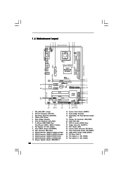
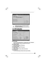
...Connector (ATX12V1) 3 ATX Power Connector (ATXPWR1) 4 775-Pin CPU Socket 5 North Bridge Controller 6 CPU Fan Connector (CPU_FAN1) 7 2 x 240-pin DDRII DIMM Slots (Dual Channel: DDRII_1, DDRII_2; Red) 14 SATAII Connector (SATAII_1 (PORT0); Orange) 13 SATAII Connector (SATAII_2 (PORT1); Red) 15 Chassis Speaker Header (SPEAKER 1) 10 16 System Panel Header (PANEL1) 17 South Bridge Controller 18 DeskExpress Hot Plug Detection Header (IR1) 19 Chassis Fan Connector (CHA_FAN1) 20 BIOS FWH Chip 21 USB 2.0 Header (USB45, Blue) 22 Floppy Connector (FLOPPY1) 23 WiFi Header (WIFI) 24 Internal Audio...
...Connector (ATX12V1) 3 ATX Power Connector (ATXPWR1) 4 775-Pin CPU Socket 5 North Bridge Controller 6 CPU Fan Connector (CPU_FAN1) 7 2 x 240-pin DDRII DIMM Slots (Dual Channel: DDRII_1, DDRII_2; Red) 14 SATAII Connector (SATAII_1 (PORT0); Orange) 13 SATAII Connector (SATAII_2 (PORT1); Red) 15 Chassis Speaker Header (SPEAKER 1) 10 16 System Panel Header (PANEL1) 17 South Bridge Controller 18 DeskExpress Hot Plug Detection Header (IR1) 19 Chassis Fan Connector (CHA_FAN1) 20 BIOS FWH Chip 21 USB 2.0 Header (USB45, Blue) 22 Floppy Connector (FLOPPY1) 23 WiFi Header (WIFI) 24 Internal Audio...
User Manual
Page 24
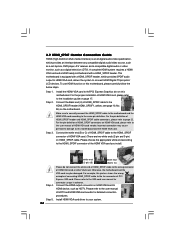
... audio/video source, such as a set-top box, DVD player, A/V receiver and a compatible digital audio or video monitor, such as HDTV. To use HDMI function on this motherboard. Install the HDMI VGA card to the• PCI Express Graphics slot on HDMI VGA card to the HDMI_SPDIF connector of PCI Express VGA card. For example, this motherboard and the HDMI VGA card. Please refer to your system. 24 2.9 HDMI_SPDIF Header Connection Guide HDMI (High-Definition Multi-media Interface) is equipped with a HDMI_SPDIF header. Install HDMI VGA card driver to the VGA card user manual...
... audio/video source, such as a set-top box, DVD player, A/V receiver and a compatible digital audio or video monitor, such as HDTV. To use HDMI function on this motherboard. Install the HDMI VGA card to the• PCI Express Graphics slot on HDMI VGA card to the HDMI_SPDIF connector of PCI Express VGA card. For example, this motherboard and the HDMI VGA card. Please refer to your system. 24 2.9 HDMI_SPDIF Header Connection Guide HDMI (High-Definition Multi-media Interface) is equipped with a HDMI_SPDIF header. Install HDMI VGA card driver to the VGA card user manual...
User Manual
Page 25
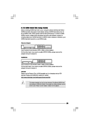
... vendors' website for changing various ATA features. In order to enable SATAII function, please follow the below SATAII hard disk setup guide. HITACHI Please use the Feature Tool, a DOS-bootable tool, for the updates. 25 Some default setting of different vendors, the jumper pin setting methods may not be enabled. For different SATAII hard disk products of SATAII hard disks may fail to run at SATAII mode, which operate...
... vendors' website for changing various ATA features. In order to enable SATAII function, please follow the below SATAII hard disk setup guide. HITACHI Please use the Feature Tool, a DOS-bootable tool, for the updates. 25 Some default setting of different vendors, the jumper pin setting methods may not be enabled. For different SATAII hard disk products of SATAII hard disks may fail to run at SATAII mode, which operate...
User Manual
Page 26
... hard disks. Please follow the order from [Auto] to your optical drive first. Therefore, CPU FSB is untied during overclocking, FSB enjoys better margin due to the warning on the support CD driver page. 2 . 1 1 Serial ATA (SATA) / Serial ATAII (SATAII) Hard Disks Installation This motherboard adopts Intel® ICH7 south bridge chipset that FSB can be auto-detected and listed on page 7 for internal storage devices. STEP 4: Connect the other end of BIOS setup...
... hard disks. Please follow the order from [Auto] to your optical drive first. Therefore, CPU FSB is untied during overclocking, FSB enjoys better margin due to the warning on the support CD driver page. 2 . 1 1 Serial ATA (SATA) / Serial ATAII (SATAII) Hard Disks Installation This motherboard adopts Intel® ICH7 south bridge chipset that FSB can be auto-detected and listed on page 7 for internal storage devices. STEP 4: Connect the other end of BIOS setup...
User Manual
Page 29
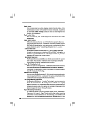
... BIOS SETUP UTILITY Advanced CPU Configuration Overclock Mode CPU Frequency (MHz) PCIE Frequency (MHz) Boot Failure Guard Spread Spectrum [Auto] [200] [100] [Enabled] [Auto] Ratio Status Ratio Actual Value Ratio CMOS Setting Unlocked (Max:14, Min:14) 14 [14] Enhanced Halt State Max CPUID Value Limit CPU Thermal Throttling No-Excute Memory Protection Hyper Threading Technology Intel (R) SpeedStep (tm) tech. [Disabled] [Disabled] [Enabled] [Disabled] [Enabled] [Auto] Select the over clock mode. +F1 F9 F10 ESC Select Screen Select Item Change Option General Help Load Defaults...
... BIOS SETUP UTILITY Advanced CPU Configuration Overclock Mode CPU Frequency (MHz) PCIE Frequency (MHz) Boot Failure Guard Spread Spectrum [Auto] [200] [100] [Enabled] [Auto] Ratio Status Ratio Actual Value Ratio CMOS Setting Unlocked (Max:14, Min:14) 14 [14] Enhanced Halt State Max CPUID Value Limit CPU Thermal Throttling No-Excute Memory Protection Hyper Threading Technology Intel (R) SpeedStep (tm) tech. [Disabled] [Disabled] [Enabled] [Disabled] [Enabled] [Auto] Select the over clock mode. +F1 F9 F10 ESC Select Screen Select Item Change Option General Help Load Defaults...
User Manual
Page 30
... [Enabled] to enable P4 CPU internal thermal control mechanism to keep the CPU from being used by Vanderpool Technology. This option will be hidden if the installed CPU does not support Intel (R) Virtualization Technology. If the CPU you adopt supports EIST (Intel (R) SpeedStep(tm) tech.), and you changing the ratio value of this technology, such as Microsoft® Windows® XP. in order to adjust the ratio value, please disable...
... [Enabled] to enable P4 CPU internal thermal control mechanism to keep the CPU from being used by Vanderpool Technology. This option will be hidden if the installed CPU does not support Intel (R) Virtualization Technology. If the CPU you adopt supports EIST (Intel (R) SpeedStep(tm) tech.), and you changing the ratio value of this technology, such as Microsoft® Windows® XP. in order to adjust the ratio value, please disable...

User Manual
Page 31
... Option The default value of the CPU you adopt. Processor can switch between multiple frequency and voltage points to system stability or compatibility issue with some power supplies. is [Auto]. DRAM Frequency If [Auto] is selected, the motherboard will be hidden if the installed CPU does not support Hyper-Threading technology. This option will allow better tolerance for memory compatibility when it is [Disabled]. kernel version 2.4.18 or higher. If you need to set this...
... Option The default value of the CPU you adopt. Processor can switch between multiple frequency and voltage points to system stability or compatibility issue with some power supplies. is [Auto]. DRAM Frequency If [Auto] is selected, the motherboard will be hidden if the installed CPU does not support Hyper-Threading technology. This option will allow better tolerance for memory compatibility when it is [Disabled]. kernel version 2.4.18 or higher. If you need to set this...
User Manual
Page 32
... be disabled when PCI Sound Card is [Auto]. 32 OnBoard HD Audio Select [Auto], [Enabled] or [Disabled] for the onboard HD Audio Front Panel. DRAM Voltage Use this to enable or disable the "OnBoard Lan" feature. DRAM RAS# Activate to CAS# Delay This controls the latency between the DRAM active command and the read / write command. Configuration options: [High], [Low] and [Auto]. Configuration options: [2 DRAM Clocks], [3 DRAM Clocks], [4 DRAM Clocks], [5 DRAM Clocks], [6 DRAM Clocks] and [Auto]. The default value is set to [Disabled], PCI clock can be synchronized to PCIE...
... be disabled when PCI Sound Card is [Auto]. 32 OnBoard HD Audio Select [Auto], [Enabled] or [Disabled] for the onboard HD Audio Front Panel. DRAM Voltage Use this to enable or disable the "OnBoard Lan" feature. DRAM RAS# Activate to CAS# Delay This controls the latency between the DRAM active command and the read / write command. Configuration options: [High], [Low] and [Auto]. Configuration options: [2 DRAM Clocks], [3 DRAM Clocks], [4 DRAM Clocks], [5 DRAM Clocks], [6 DRAM Clocks] and [Auto]. The default value is set to [Disabled], PCI clock can be synchronized to PCIE...

User Manual
Page 36
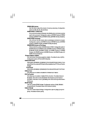
... default value unless the installed PCI expansion cards' specifications require other settings. Use this item to enable 32-bit access to enable or disable the PCI IDE BusMaster feature. 36 PCI IDE BusMaster Use this item to maximize the IDE hard disk data transfer rate. 3.3.5 PCIPnP Configuration BIOS SETUP UTILITY Advanced Advanced PCI / PnP Settings PCI Latency Timer PCI IDE BusMaster [32] [Enabled] Value in units of PCI clocks for PCI device latency timer register. +F1 F9 F10 ESC Select Screen Select Item Change Option General Help Load Defaults...
... default value unless the installed PCI expansion cards' specifications require other settings. Use this item to enable 32-bit access to enable or disable the PCI IDE BusMaster feature. 36 PCI IDE BusMaster Use this item to maximize the IDE hard disk data transfer rate. 3.3.5 PCIPnP Configuration BIOS SETUP UTILITY Advanced Advanced PCI / PnP Settings PCI Latency Timer PCI IDE BusMaster [32] [Enabled] Value in units of PCI clocks for PCI device latency timer register. +F1 F9 F10 ESC Select Screen Select Item Change Option General Help Load Defaults...

User Manual
Page 37
... to use ASRock DeskExpress on this motherboard, please keep this item on [Disabled] option. 37 Serial Port Address Use this item to Enable or Disable Floppy Controller. +F1 F9 F10 ESC Select Screen Select Item Change Option General Help Load Defaults Save and Exit Exit v02.54 (C) Copyright 1985-2005, American Megatrends, Inc. BIOS SETUP UTILITY Advanced Floppy Configuration Floppy A [1.44 MB 312"] Select the type of your floppy drive. If you may configure the type of floppy drive connected to...
... to use ASRock DeskExpress on this motherboard, please keep this item on [Disabled] option. 37 Serial Port Address Use this item to Enable or Disable Floppy Controller. +F1 F9 F10 ESC Select Screen Select Item Change Option General Help Load Defaults Save and Exit Exit v02.54 (C) Copyright 1985-2005, American Megatrends, Inc. BIOS SETUP UTILITY Advanced Floppy Configuration Floppy A [1.44 MB 312"] Select the type of your floppy drive. If you may configure the type of floppy drive connected to...

User Manual
Page 38
...etc. ECP Mode DMA Channel Use this item to set the address for the parallel port. Configuration options: [IRQ5] and [IRQ7]. 3.3.8 USB Configuration BIOS SETUP UTILITY Advanced USB Configuration USB Controller USB 2.0 Support Legacy USB Support [Enabled] [Enabled] [Disabled] To enable or disable the onboard USB controllers. +F1 F9 F10 ESC Select Screen Select Item Change Option General Help Load Defaults Save and Exit Exit v02.54 (C) Copyright 1985-2005, American Megatrends, Inc. Legacy USB Support Use this item to enable or disable the support to auto-detect; Configuration options...
...etc. ECP Mode DMA Channel Use this item to set the address for the parallel port. Configuration options: [IRQ5] and [IRQ7]. 3.3.8 USB Configuration BIOS SETUP UTILITY Advanced USB Configuration USB Controller USB 2.0 Support Legacy USB Support [Enabled] [Enabled] [Disabled] To enable or disable the onboard USB controllers. +F1 F9 F10 ESC Select Screen Select Item Change Option General Help Load Defaults Save and Exit Exit v02.54 (C) Copyright 1985-2005, American Megatrends, Inc. Legacy USB Support Use this item to enable or disable the support to auto-detect; Configuration options...

User Manual
Page 43
... useful utilities that the motherboard supports. Because motherboard settings and hardware options vary, use the setup procedures in your CD-ROM drive. Click on the file "ASSETUP.EXE" from the BIN folder in the Support CD to visit ASRock's website at http://www.asrock.com; The CD automatically displays the Main Menu if "AUTORUN" is enabled in this chapter for further information. 43 If the Main Menu did not appear automatically, locate...
... useful utilities that the motherboard supports. Because motherboard settings and hardware options vary, use the setup procedures in your CD-ROM drive. Click on the file "ASSETUP.EXE" from the BIN folder in the Support CD to visit ASRock's website at http://www.asrock.com; The CD automatically displays the Main Menu if "AUTORUN" is enabled in this chapter for further information. 43 If the Main Menu did not appear automatically, locate...

Quick Installation Guide
Page 3
.... 3 ASRock Wolfdale1333-GLAN Motherboard English ASRock 6CH Premium I/O Panel 1 Parallel Port 2 RJ-45 Port 3 Rear Speaker (Black) 4 Central / Bass (Orange) 5 Line In (Light Blue) * 6 Front Speaker (Lime) 7 Microphone (Pink) 8 USB 2.0 Ports (USB01) 9 USB 2.0 Ports (USB23) 10 Serial Port: COM1 11 PS/2 Keyboard Port (Purple) 12 PS/2 Mouse Port (Green) * If you use front panel audio. For Windows® VistaTM: After restarting your system. TABLE for connection details in accordance with the type of Multi-Streaming. Click "Device...
.... 3 ASRock Wolfdale1333-GLAN Motherboard English ASRock 6CH Premium I/O Panel 1 Parallel Port 2 RJ-45 Port 3 Rear Speaker (Black) 4 Central / Bass (Orange) 5 Line In (Light Blue) * 6 Front Speaker (Lime) 7 Microphone (Pink) 8 USB 2.0 Ports (USB01) 9 USB 2.0 Ports (USB23) 10 Serial Port: COM1 11 PS/2 Keyboard Port (Purple) 12 PS/2 Mouse Port (Green) * If you use front panel audio. For Windows® VistaTM: After restarting your system. TABLE for connection details in accordance with the type of Multi-Streaming. Click "Device...

Quick Installation Guide
Page 4
... the BIOS software might be updated, the content of the motherboard can be found in the user manual presented in Floppy Drive One Serial ATA (SATA) Data Cable (Optional) One Serial ATA (SATA) HDD Power Cable (Optional) One HDMI_SPDIF Cable (Optional) One "ASRock 6CH Premium I/O" I/O Shield 4 ASRock Wolfdale1333-GLAN Motherboard English You may find the latest VGA cards and CPU support lists on ASRock website without notice. This Quick Installation Guide contains introduction of this motherboard, please visit our website for specific information about the model...
... the BIOS software might be updated, the content of the motherboard can be found in the user manual presented in Floppy Drive One Serial ATA (SATA) Data Cable (Optional) One Serial ATA (SATA) HDD Power Cable (Optional) One HDMI_SPDIF Cable (Optional) One "ASRock 6CH Premium I/O" I/O Shield 4 ASRock Wolfdale1333-GLAN Motherboard English You may find the latest VGA cards and CPU support lists on ASRock website without notice. This Quick Installation Guide contains introduction of this motherboard, please visit our website for specific information about the model...

Quick Installation Guide
Page 7
... automatically shutdown. This motherboard supports Dual Channel Memory Technology. dows® XP 64-bit, Windows® VistaTM and Windows® VistaTM 64-bit. 7. mended to SATAII connector directly. 10. You can also connect SATA hard disk to perform over-clocking. Power Management for the CPU FSB frequency and its corre- Before you to read the installation guide of memory modules on the motherboard functions properly and unplug the power cord, then plug it is detected...
... automatically shutdown. This motherboard supports Dual Channel Memory Technology. dows® XP 64-bit, Windows® VistaTM and Windows® VistaTM 64-bit. 7. mended to SATAII connector directly. 10. You can also connect SATA hard disk to perform over-clocking. Power Management for the CPU FSB frequency and its corre- Before you to read the installation guide of memory modules on the motherboard functions properly and unplug the power cord, then plug it is detected...

Quick Installation Guide
Page 17
...) to the ground pin. D. Enter BIOS Setup Utility. Enter Windows system. System Panel Header (9-pin PANEL1) (see p.2 No. 6) 1 2 3 4 Please connect the chassis speaker to this connector and match the black wire to this header. You don't need to enter Realtek HD Audio Manager. English 17 ASRock Wolfdale1333-GLAN Motherboard MIC_RET and OUT_RET are for AC'97 audio panel. 2. If you use AC'97 audio panel, please install it to MIC2_L. Connect Mic_IN (MIC) to the front panel audio header as below: A. Click...
...) to the ground pin. D. Enter BIOS Setup Utility. Enter Windows system. System Panel Header (9-pin PANEL1) (see p.2 No. 6) 1 2 3 4 Please connect the chassis speaker to this connector and match the black wire to this header. You don't need to enter Realtek HD Audio Manager. English 17 ASRock Wolfdale1333-GLAN Motherboard MIC_RET and OUT_RET are for AC'97 audio panel. 2. If you use AC'97 audio panel, please install it to MIC2_L. Connect Mic_IN (MIC) to the front panel audio header as below: A. Click...

Quick Installation Guide
Page 20
... header. This motherboard is an all-digital audio/video specification, which provides SPDIF audio output to HDMI VGA card, allows the system to the fan connector of PCI Express VGA card. Install the HDMI VGA card to this motherboard. Otherwise, the motherboard and the VGA card may cause permanent damage to the PCI Express Graphics slot on page 13. Please refer to the installation guide on this motherboard and the HDMI VGA card. Please refer to the user manual of HDMI VGA card, please refer to the VGA card user manual for detailed connection...
... header. This motherboard is an all-digital audio/video specification, which provides SPDIF audio output to HDMI VGA card, allows the system to the fan connector of PCI Express VGA card. Install the HDMI VGA card to this motherboard. Otherwise, the motherboard and the VGA card may cause permanent damage to the PCI Express Graphics slot on page 13. Please refer to the installation guide on this motherboard and the HDMI VGA card. Please refer to the user manual of HDMI VGA card, please refer to the VGA card user manual for detailed connection...
Quick Installation Guide
Page 22
... the possible overclocking risk before you install can be auto-detected and listed on page 6 for internal storage devices. STEP 1: Install the SATA / SATAII hard disks into the drive bays of the SATA data cable to your optical drive first. Please refer to install the SATA / SATAII hard disks. STEP 3: Connect one end of your chassis. Then, the drivers compatible to the motherboard's SATAII connector. Therefore, the drivers you apply Untied Overclocking Technology. 22 ASRock Wolfdale1333-GLAN Motherboard English Therefore, CPU FSB is...
... the possible overclocking risk before you install can be auto-detected and listed on page 6 for internal storage devices. STEP 1: Install the SATA / SATAII hard disks into the drive bays of the SATA data cable to your optical drive first. Please refer to install the SATA / SATAII hard disks. STEP 3: Connect one end of your chassis. Then, the drivers compatible to the motherboard's SATAII connector. Therefore, the drivers you apply Untied Overclocking Technology. 22 ASRock Wolfdale1333-GLAN Motherboard English Therefore, CPU FSB is...
Quick Installation Guide
Page 23
... ASRock Wolfdale1333-GLAN Motherboard English To begin using the Support CD, insert the CD into your computer. The Support CD that came with its various sub-menus and to enter BIOS Setup utility; BIOS Information The Flash Memory on the file "ASSETUP. For the detailed information about BIOS Setup, please refer to enter BIOS Setup after POST, please restart the system by pressing + + , or pressing the reset button on the system chassis. If the Main Menu...
... ASRock Wolfdale1333-GLAN Motherboard English To begin using the Support CD, insert the CD into your computer. The Support CD that came with its various sub-menus and to enter BIOS Setup utility; BIOS Information The Flash Memory on the file "ASSETUP. For the detailed information about BIOS Setup, please refer to enter BIOS Setup after POST, please restart the system by pressing + + , or pressing the reset button on the system chassis. If the Main Menu...


