User Manual
Page 8
... motherboard supports Untied Overclocking Technology. Before you adopt a DDR2 533 memory module. 6. sponding memory support frequency. Before installing SATAII hard disk to SATAII connector, please read "Untied Overclocking Technology" on the motherboard functions properly and unplug the power cord, then plug it back again. mended to SATAII connector directly. 11. You can also connect SATA hard disk to perform over-clocking. While CPU overheat is not recom- Please read the "SATAII Hard Disk Setup Guide" on this situation, PCIE frequency...
... motherboard supports Untied Overclocking Technology. Before you adopt a DDR2 533 memory module. 6. sponding memory support frequency. Before installing SATAII hard disk to SATAII connector, please read "Untied Overclocking Technology" on the motherboard functions properly and unplug the power cord, then plug it back again. mended to SATAII connector directly. 11. You can also connect SATA hard disk to perform over-clocking. While CPU overheat is not recom- Please read the "SATAII Hard Disk Setup Guide" on this situation, PCIE frequency...
User Manual
Page 10
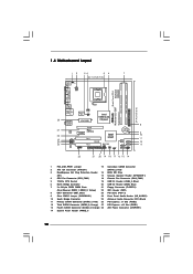
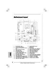
... Express x1 Slot (PCIE2) 12 Third SATAII Connector (SATAII_3; Orange) 27 PCI Express x16 Slot (PCIE1) 13 Fourth SATAII Connector (SATAII_4; Orange) 28 ATX Power Connector (ATXPWR1) 14 System Panel Header (PANEL1) 10 Red) 3 DeskExpress Hot Plug Detection Header 16 BIOS SPI Chip (IR1) 17 Chassis Speaker Header (SPEAKER 1) 4 CPU Fan Connector (CPU_FAN1) 18 Chassis Fan Connector (CHA_FAN1) 5 775-Pin CPU Socket 19 USB 2.0 Header (USB4_5, Blue) 6 North Bridge Controller 20 USB 2.0 Header (USB6, Blue) 7 2 x 240-pin DDR2 DIMM Slots 21 Floppy Connector (FLOPPY1) (Dual Channel...
... Express x1 Slot (PCIE2) 12 Third SATAII Connector (SATAII_3; Orange) 27 PCI Express x16 Slot (PCIE1) 13 Fourth SATAII Connector (SATAII_4; Orange) 28 ATX Power Connector (ATXPWR1) 14 System Panel Header (PANEL1) 10 Red) 3 DeskExpress Hot Plug Detection Header 16 BIOS SPI Chip (IR1) 17 Chassis Speaker Header (SPEAKER 1) 4 CPU Fan Connector (CPU_FAN1) 18 Chassis Fan Connector (CHA_FAN1) 5 775-Pin CPU Socket 19 USB 2.0 Header (USB4_5, Blue) 6 North Bridge Controller 20 USB 2.0 Header (USB6, Blue) 7 2 x 240-pin DDR2 DIMM Slots 21 Floppy Connector (FLOPPY1) (Dual Channel...

User Manual
Page 23
... want to enable SATAII 3.0Gb/s, please remove the jumpers from pin 3 and pin 4. In order to enable SATAII function, please follow the below SATAII hard disk setup guide. Please visit the vendors' website for changing various ATA features. Some default setting of different vendors, the jumper pin setting methods may not be enabled. SAMSUNG 7531 8642 If pin 3 and pin 4 are shorted, SATA 1.5Gb/s will be at SATAII mode. HITACHI Please use the...
... want to enable SATAII 3.0Gb/s, please remove the jumpers from pin 3 and pin 4. In order to enable SATAII function, please follow the below SATAII hard disk setup guide. Please visit the vendors' website for changing various ATA features. Some default setting of different vendors, the jumper pin setting methods may not be enabled. SAMSUNG 7531 8642 If pin 3 and pin 4 are shorted, SATA 1.5Gb/s will be at SATAII mode. HITACHI Please use the...

User Manual
Page 24
... support CD driver page. You may install SATA / SATAII hard disks on this motherboard for the possible overclocking risk before you enable Untied Overclocking function, please enter "Overclock Mode" option of the SATA data cable to the SATA / SATAII hard disk. 2.11 Driver Installation Guide To install the drivers to your system can be auto-detected and listed on page 7 for internal storage devices. STEP 2: Connect the SATA power cable to fixed PCI / PCIE buses. Therefore, the drivers you to install those required drivers. Then, the drivers compatible to the motherboard...
... support CD driver page. You may install SATA / SATAII hard disks on this motherboard for the possible overclocking risk before you enable Untied Overclocking function, please enter "Overclock Mode" option of the SATA data cable to the SATA / SATAII hard disk. 2.11 Driver Installation Guide To install the drivers to your system can be auto-detected and listed on page 7 for internal storage devices. STEP 2: Connect the SATA power cable to fixed PCI / PCIE buses. Therefore, the drivers you to install those required drivers. Then, the drivers compatible to the motherboard...
User Manual
Page 27
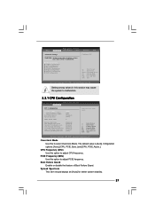
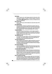
...Use this option to Sub Screen F1 General Help F9 Load Defaults F10 Save and Exit ESC Exit v02.54 (C) Copyright 1985-2005, American Megatrends, Inc. CPU Configuration Chipset Configuration ACPI Configuration IDE Configuration PCIPnP Configuration Floppy Configuration SuperIO Configuration USB Configuration Configure CPU Select Screen Select Item Enter Go to adjust PCIE frequency. Boot Failure Guard Enable or disable the feature of Boot Failure Guard. Spread Spectrum This item should always be [Auto] for better system stability. 27 BIOS SETUP UTILITY Main Advanced H/W Monitor...
...Use this option to Sub Screen F1 General Help F9 Load Defaults F10 Save and Exit ESC Exit v02.54 (C) Copyright 1985-2005, American Megatrends, Inc. CPU Configuration Chipset Configuration ACPI Configuration IDE Configuration PCIPnP Configuration Floppy Configuration SuperIO Configuration USB Configuration Configure CPU Select Screen Select Item Enter Go to adjust PCIE frequency. Boot Failure Guard Enable or disable the feature of Boot Failure Guard. Spread Spectrum This item should always be [Auto] for better system stability. 27 BIOS SETUP UTILITY Main Advanced H/W Monitor...
User Manual
Page 28
...) Memory Protection" can utilize the additional hardware capabilities provided by malicious software to allow you plan to [Enabled] if using Microsoft® Windows® XP, or Linux 28 When this feature, it shows "Unlocked", you changing the ratio value of the system caches. This option will find this motherboard. Intel (R) Virtualization tech. CPU Thermal Throttling You may select [Enabled] to enable P4 CPU internal thermal control...
...) Memory Protection" can utilize the additional hardware capabilities provided by malicious software to allow you plan to [Enabled] if using Microsoft® Windows® XP, or Linux 28 When this feature, it shows "Unlocked", you changing the ratio value of the system caches. This option will find this motherboard. Intel (R) Virtualization tech. CPU Thermal Throttling You may select [Enabled] to enable P4 CPU internal thermal control...

User Manual
Page 29
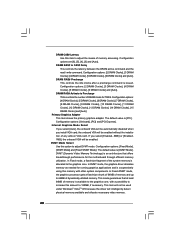
... Configuration BIOS SETUP UTILITY Advanced Chipset Configuration DRAM Frequency [Auto] Flexibility Option [Disabled] DRAM CAS# Latency [Auto] DRAM RAS# to CAS# Delay [Auto] DRAM RAS# Precharge [Auto] DRAM RAS# Activate to Precharge [Auto] Options Auto 200MHz 266MHz 333MHz (DDRII400) (DDRII533) (DDRII667) Primary Graphics Adapter Internal Graphics Mode Select DVMT Mode Select DVMT/FIXED Memory OnBoard HD Audio Front Panel OnBoard Lan PCI Fix Function [PCI] [Auto] [DVMT Mode] [Maximum DVMT] [Auto] [Auto] [Enabled] [Enabled] +F1 F9 F10 ESC Select Screen Select Item Change...
... Configuration BIOS SETUP UTILITY Advanced Chipset Configuration DRAM Frequency [Auto] Flexibility Option [Disabled] DRAM CAS# Latency [Auto] DRAM RAS# to CAS# Delay [Auto] DRAM RAS# Precharge [Auto] DRAM RAS# Activate to Precharge [Auto] Options Auto 200MHz 266MHz 333MHz (DDRII400) (DDRII533) (DDRII667) Primary Graphics Adapter Internal Graphics Mode Select DVMT Mode Select DVMT/FIXED Memory OnBoard HD Audio Front Panel OnBoard Lan PCI Fix Function [PCI] [Auto] [DVMT Mode] [Maximum DVMT] [Auto] [Auto] [Enabled] [Enabled] +F1 F9 F10 ESC Select Screen Select Item Change...
User Manual
Page 30
... video memory. 30 This mode guarantees that offers breakthrough performance for the motherboard through efficient memory utilization. DRAM RAS# to the graphics core, with other system components. Internal Graphics Mode Select If you install VGA card; Configuration options: [2 DRAM Clocks], [3 DRAM Clocks], [4 DRAM Clocks], [5 DRAM Clocks], [6 DRAM Clocks] and [Auto]. Configuration options: [Onboard], [PCI] and [PCI Express]. DVMT Mode Select Use this amount to 64MB of memory accessing. In DVMT mode, the graphics driver allocates memory as needed for TRAS. Configuration options...
... video memory. 30 This mode guarantees that offers breakthrough performance for the motherboard through efficient memory utilization. DRAM RAS# to the graphics core, with other system components. Internal Graphics Mode Select If you install VGA card; Configuration options: [2 DRAM Clocks], [3 DRAM Clocks], [4 DRAM Clocks], [5 DRAM Clocks], [6 DRAM Clocks] and [Auto]. Configuration options: [Onboard], [PCI] and [PCI Express]. DVMT Mode Select Use this amount to 64MB of memory accessing. In DVMT mode, the graphics driver allocates memory as needed for TRAS. Configuration options...
User Manual
Page 35
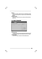
... disable the PCI IDE BusMaster feature. 35 PCI IDE BusMaster Use this item to enable 32-bit access to enable or disable the S.M.A.R.T. (Self-Monitoring, Analysis, and Reporting Technology) feature. Use this item to maximize the IDE hard disk data transfer rate. 3.3.5 PCIPnP Configuration BIOS SETUP UTILITY Advanced Advanced PCI / PnP Settings PCI Latency Timer PCI IDE BusMaster [32] [Enabled] Value in units of PCI clocks for PCI device latency timer register. +F1 F9 F10 ESC Select Screen Select Item Change Option General Help Load Defaults...
... disable the PCI IDE BusMaster feature. 35 PCI IDE BusMaster Use this item to enable 32-bit access to enable or disable the S.M.A.R.T. (Self-Monitoring, Analysis, and Reporting Technology) feature. Use this item to maximize the IDE hard disk data transfer rate. 3.3.5 PCIPnP Configuration BIOS SETUP UTILITY Advanced Advanced PCI / PnP Settings PCI Latency Timer PCI IDE BusMaster [32] [Enabled] Value in units of PCI clocks for PCI device latency timer register. +F1 F9 F10 ESC Select Screen Select Item Change Option General Help Load Defaults...
User Manual
Page 36
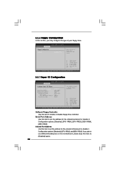
... to enable or disable floppy drive controller. OnBoard Floppy Controller Use this item to set the address for the onboard infrared port or disable it . If you may configure the type of floppy drive connected to the system. +F1 F9 F10 ESC Select Screen Select Item Change Option General Help Load Defaults Save and Exit Exit v02.54 (C) Copyright 1985-2005, American Megatrends, Inc. 3.3.7 Super IO Configuration BIOS SETUP UTILITY Advanced Configure Super IO Chipset OnBoard Floppy Controller Serial Port Address Infrared Port Address Parallel Port...
... to enable or disable floppy drive controller. OnBoard Floppy Controller Use this item to set the address for the onboard infrared port or disable it . If you may configure the type of floppy drive connected to the system. +F1 F9 F10 ESC Select Screen Select Item Change Option General Help Load Defaults Save and Exit Exit v02.54 (C) Copyright 1985-2005, American Megatrends, Inc. 3.3.7 Super IO Configuration BIOS SETUP UTILITY Advanced Configure Super IO Chipset OnBoard Floppy Controller Serial Port Address Infrared Port Address Parallel Port...
User Manual
Page 37
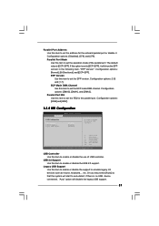
... the onboard parallel port or disable it will show the EPP version in the following item, "EPP Version". Configuration options: [Disabled], [378], and [278]. If this option is set the operation mode of USB controller. Configuration options: [1.9] and [1.7]. Configuration options: [IRQ5] and [IRQ7]. 3.3.8 USB Configuration BIOS SETUP UTILITY Advanced USB Configuration USB Controller USB 2.0 Support Legacy USB Support [Enabled] [Enabled] [Disabled] To enable or disable the onboard USB controllers. +F1 F9 F10 ESC Select Screen Select Item Change Option General Help Load Defaults Save...
... the onboard parallel port or disable it will show the EPP version in the following item, "EPP Version". Configuration options: [Disabled], [378], and [278]. If this option is set the operation mode of USB controller. Configuration options: [1.9] and [1.7]. Configuration options: [IRQ5] and [IRQ7]. 3.3.8 USB Configuration BIOS SETUP UTILITY Advanced USB Configuration USB Controller USB 2.0 Support Legacy USB Support [Enabled] [Enabled] [Disabled] To enable or disable the onboard USB controllers. +F1 F9 F10 ESC Select Screen Select Item Change Option General Help Load Defaults Save...

User Manual
Page 42
... the Main Menu did not appear automatically, locate and double click on a specific item then follow the installation wizard to install it. 4.2.4 Contact Information If you may contact your CD-ROM drive. Because motherboard settings and hardware options vary, use the setup procedures in your computer. Please install the necessary drivers to display the menus. 4.2.2 Drivers Menu The Drivers Menu shows the available devices drivers if the system detects installed devices. Click on the file...
... the Main Menu did not appear automatically, locate and double click on a specific item then follow the installation wizard to install it. 4.2.4 Contact Information If you may contact your CD-ROM drive. Because motherboard settings and hardware options vary, use the setup procedures in your computer. Please install the necessary drivers to display the menus. 4.2.2 Drivers Menu The Drivers Menu shows the available devices drivers if the system detects installed devices. Click on the file...
Quick Installation Guide
Page 2
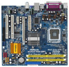
Orange) 28 ATX Power Connector (ATXPWR1) 14 System Panel Header (PANEL1) 2 ASRock Wolfdale1333-D667 Motherboard Red) 26 PCI Express x1 Slot (PCIE2) 12 Third SATAII Connector (SATAII_3; Red) 3 DeskExpress Hot Plug Detection Header 16 BIOS SPI Chip (IR1) 17 Chassis Speaker Header (SPEAKER 1) 4 CPU Fan Connector (CPU_FAN1) 18 Chassis Fan Connector (CHA_FAN1) 5 775-Pin CPU Socket 19 USB 2.0 Header (USB4_5, Blue) 6 North Bridge Controller 20 USB 2.0 Header (USB6, Blue) 7 2 x 240-pin DDR2 DIMM Slots 21 Floppy Connector (FLOPPY1) (Dual Channel: DDRII_1, DDRII_2; Yellow)...
Orange) 28 ATX Power Connector (ATXPWR1) 14 System Panel Header (PANEL1) 2 ASRock Wolfdale1333-D667 Motherboard Red) 26 PCI Express x1 Slot (PCIE2) 12 Third SATAII Connector (SATAII_3; Red) 3 DeskExpress Hot Plug Detection Header 16 BIOS SPI Chip (IR1) 17 Chassis Speaker Header (SPEAKER 1) 4 CPU Fan Connector (CPU_FAN1) 18 Chassis Fan Connector (CHA_FAN1) 5 775-Pin CPU Socket 19 USB 2.0 Header (USB4_5, Blue) 6 North Bridge Controller 20 USB 2.0 Header (USB6, Blue) 7 2 x 240-pin DDR2 DIMM Slots 21 Floppy Connector (FLOPPY1) (Dual Channel: DDRII_1, DDRII_2; Yellow)...

Quick Installation Guide
Page 7
... Hard Disk Setup Guide" on page 19 to adjust your SATAII hard disk drive to the chipset limitation, the actual memory size may cause the instability of memory modules on the motherboard functions properly and unplug the power cord, then plug it will operate in the support CD. 3. Under this situation, PCIE frequency will automatically shutdown. Before you use a FSB1333-CPU on page 20 for USB 2.0 works fine under Windows® XP, Win...
... Hard Disk Setup Guide" on page 19 to adjust your SATAII hard disk drive to the chipset limitation, the actual memory size may cause the instability of memory modules on the motherboard functions properly and unplug the power cord, then plug it will operate in the support CD. 3. Under this situation, PCIE frequency will automatically shutdown. Before you use a FSB1333-CPU on page 20 for USB 2.0 works fine under Windows® XP, Win...
Quick Installation Guide
Page 13
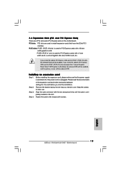
... PCI Express VGA card to PCIE1 (PCIE x16 slot) and adjust the "Internal Graphics Mode Select" BIOS option to [Enabled], the onboard VGA will be enabled, and the primary screen will be onboard VGA. Before installing the expansion card, please make necessary hardware settings for PCI Express cards with screws. 13 ASRock Wolfdale1333-D667 Motherboard English If you intend to use . 2.4 Expansion Slots (PCI and PCI Express Slots) There are used to install expansion cards that have the 32-bit PCI interface. Step 4. Remove the bracket facing the slot that the power supply...
... PCI Express VGA card to PCIE1 (PCIE x16 slot) and adjust the "Internal Graphics Mode Select" BIOS option to [Enabled], the onboard VGA will be enabled, and the primary screen will be onboard VGA. Before installing the expansion card, please make necessary hardware settings for PCI Express cards with screws. 13 ASRock Wolfdale1333-D667 Motherboard English If you intend to use . 2.4 Expansion Slots (PCI and PCI Express Slots) There are used to install expansion cards that have the 32-bit PCI interface. Step 4. Remove the bracket facing the slot that the power supply...

Quick Installation Guide
Page 16
... network (WLAN) adapter. English 16 ASRock Wolfdale1333-D667 Motherboard USB 2.0 Headers (9-pin USB4_5) (see p.2 No. 19) (4-pin USB6) (see p.2 No. 20) Besides four default USB 2.0 ports on the I/O panel, there are two USB 2.0 headers on this motherboard, this header can support one USB 2.0 port. This is an interface for proper installation. It allows you CD1 to receive stereo audio input from sound sources such as a 4-Pin USB 2.0 header to -use WiFi+AP functin on this motherboard. To connect the 4-Pin USB device cable...
... network (WLAN) adapter. English 16 ASRock Wolfdale1333-D667 Motherboard USB 2.0 Headers (9-pin USB4_5) (see p.2 No. 19) (4-pin USB6) (see p.2 No. 20) Besides four default USB 2.0 ports on the I/O panel, there are two USB 2.0 headers on this motherboard, this header can support one USB 2.0 port. This is an interface for proper installation. It allows you CD1 to receive stereo audio input from sound sources such as a 4-Pin USB 2.0 header to -use WiFi+AP functin on this motherboard. To connect the 4-Pin USB device cable...

Quick Installation Guide
Page 17
... correctly. Enter BIOS Setup Utility. F. Connect Ground (GND) to the front panel audio header as below: A. E. Enter Windows system. For Windows® 2000 / XP / XP 64-bit OS: Click "Audio I/O", select "Connector Settings" , choose "Disable front panel jack detection", and save the change by clicking "OK". 1. If you use AC'97 audio panel, please install it to Ground (GND). Enter Advanced Settings, and then select Chipset Configuration. Click the icon on the chassis must support HDA to connect them...
... correctly. Enter BIOS Setup Utility. F. Connect Ground (GND) to the front panel audio header as below: A. E. Enter Windows system. For Windows® 2000 / XP / XP 64-bit OS: Click "Audio I/O", select "Connector Settings" , choose "Disable front panel jack detection", and save the change by clicking "OK". 1. If you use AC'97 audio panel, please install it to Ground (GND). Enter Advanced Settings, and then select Chipset Configuration. Click the icon on the chassis must support HDA to connect them...

Quick Installation Guide
Page 19
... Digital If pin 5 and pin 6 are just for details: http://www.hitachigst.com/hdd/support/download.htm The above examples are shorted, SATA 1.5Gb/s will be the same. HITACHI Please use the Feature Tool, a DOS-bootable tool, for the updates. In order to enable SATAII function, please follow the below SATAII hard disk setup guide. English 19 ASRock Wolfdale1333-D667 Motherboard tion 13 1 2 . 7 SATAII Hard Disk Setup Guide Before installing SATAII hard disk to your...
... Digital If pin 5 and pin 6 are just for details: http://www.hitachigst.com/hdd/support/download.htm The above examples are shorted, SATA 1.5Gb/s will be the same. HITACHI Please use the Feature Tool, a DOS-bootable tool, for the updates. In order to enable SATAII function, please follow the below SATAII hard disk setup guide. English 19 ASRock Wolfdale1333-D667 Motherboard tion 13 1 2 . 7 SATAII Hard Disk Setup Guide Before installing SATAII hard disk to your...

Quick Installation Guide
Page 20
... will guide you enable Untied Overclocking function, please enter "Overclock Mode" option of your system can be auto-detected and listed on the support CD driver page. STEP 1: Install the SATA / SATAII hard disks into the drive bays of BIOS setup to set the selection from up to bottom side to the SATA / SATAII hard disk. Therefore, CPU FSB is untied during overclocking, FSB enjoys better margin due to the warning on this motherboard for...
... will guide you enable Untied Overclocking function, please enter "Overclock Mode" option of your system can be auto-detected and listed on the support CD driver page. STEP 1: Install the SATA / SATAII hard disks into the drive bays of BIOS setup to set the selection from up to bottom side to the SATA / SATAII hard disk. Therefore, CPU FSB is untied during overclocking, FSB enjoys better margin due to the warning on this motherboard for...

Quick Installation Guide
Page 21
... the motherboard stores BIOS Setup Utility. otherwise, POST continues with the motherboard contains necessary drivers and useful utilities that will display the Main Menu automatically if "AUTORUN" is designed to be user-friendly. The Support CD that came with its various sub-menus and to enter BIOS Setup utility; When you to enter BIOS Setup after POST, please restart the system by pressing + + , or pressing the reset button on the system chassis. Software Support CD information This motherboard supports...
... the motherboard stores BIOS Setup Utility. otherwise, POST continues with the motherboard contains necessary drivers and useful utilities that will display the Main Menu automatically if "AUTORUN" is designed to be user-friendly. The Support CD that came with its various sub-menus and to enter BIOS Setup utility; When you to enter BIOS Setup after POST, please restart the system by pressing + + , or pressing the reset button on the system chassis. Software Support CD information This motherboard supports...


