User Manual
Page 10
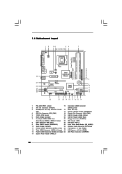
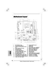
...Hot Plug Detection Header 16 BIOS SPI Chip (IR1) 17 Chassis Speaker Header (SPEAKER 1) 4 CPU Fan Connector (CPU_FAN1) 18 Chassis Fan Connector (CHA_FAN1) 5 775-Pin CPU Socket 19 USB 2.0 Header (USB4_5, Blue) 6 North Bridge Controller 20 USB 2.0 Header (USB6, Blue) 7 2 x 240-pin DDR2 DIMM Slots 21 Floppy ...)0 Dual Core CPU PARALLEL PORT COM1 VGA1 28 27 26 25 24 23 Top: Line In Center: Line Out Bottom: Mic In Dual Channel Wolfdale1333-D667 USB 2.0 T: USB2 B: USB3 USB 2.0 T: USB0 B: USB1 Top: RJ-45 Super IO CPU_FAN1 1 IR1 ATXPWR1 Intel 945GC A2 Chipset LAN...
...Hot Plug Detection Header 16 BIOS SPI Chip (IR1) 17 Chassis Speaker Header (SPEAKER 1) 4 CPU Fan Connector (CPU_FAN1) 18 Chassis Fan Connector (CHA_FAN1) 5 775-Pin CPU Socket 19 USB 2.0 Header (USB4_5, Blue) 6 North Bridge Controller 20 USB 2.0 Header (USB6, Blue) 7 2 x 240-pin DDR2 DIMM Slots 21 Floppy ...)0 Dual Core CPU PARALLEL PORT COM1 VGA1 28 27 26 25 24 23 Top: Line In Center: Line Out Bottom: Mic In Dual Channel Wolfdale1333-D667 USB 2.0 T: USB2 B: USB3 USB 2.0 T: USB0 B: USB1 Top: RJ-45 Super IO CPU_FAN1 1 IR1 ATXPWR1 Intel 945GC A2 Chipset LAN...

User Manual
Page 13
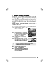
...Locate Pin1 and the two orientation key notches. Step 1. Insert the 775-LAND CPU: Step 2-1. black line black line Step 2-2. Pin1 orientation key notch orientation key notch Pin1 alignment key alignment key 775-LAND CPU 775-Pin Socket 13 Otherwise, the CPU will be seriously damaged. Rotate the load ...plate to insert the CPU into the socket, please check if the CPU surface is unclean or if there ...
...Locate Pin1 and the two orientation key notches. Step 1. Insert the 775-LAND CPU: Step 2-1. black line black line Step 2-2. Pin1 orientation key notch orientation key notch Pin1 alignment key alignment key 775-LAND CPU 775-Pin Socket 13 Otherwise, the CPU will be seriously damaged. Rotate the load ...plate to insert the CPU into the socket, please check if the CPU surface is unclean or if there ...
User Manual
Page 15
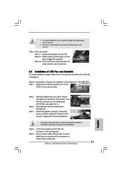
... Step 3. Repeat with the motherboard throughholes. Connect fan header with 775-Pin socket that the CPU and the heatsink are oriented on side closest to install and lock. Please adopt the type of the heatsink for 775-LAND CPU. Then connect the CPU fan to ensure cable does ...Step 5. Rotate the fastener clockwise, then press down the fasteners without rotating them clockwise, the heatsink cannot be secured on fastener caps with Intel 775-LAND CPU to improve heat dissipation. If you need to spray thermal interface material between the CPU and the heatsink to dissipate heat. Step ...
... Step 3. Repeat with the motherboard throughholes. Connect fan header with 775-Pin socket that the CPU and the heatsink are oriented on side closest to install and lock. Please adopt the type of the heatsink for 775-LAND CPU. Then connect the CPU fan to ensure cable does ...Step 5. Rotate the fastener clockwise, then press down the fasteners without rotating them clockwise, the heatsink cannot be secured on fastener caps with Intel 775-LAND CPU to improve heat dissipation. If you need to spray thermal interface material between the CPU and the heatsink to dissipate heat. Step ...
Quick Installation Guide
Page 2
Orange) 28 ATX Power Connector (ATXPWR1) 14 System Panel Header (PANEL1) 2 ASRock Wolfdale1333-D667 Motherboard Red) 26 PCI Express x1 Slot (PCIE2) 12 Third SATAII Connector (SATAII_3; Orange) 27 PCI Express x16 Slot (PCIE1) 13 Fourth ... DeskExpress Hot Plug Detection Header 16 BIOS SPI Chip (IR1) 17 Chassis Speaker Header (SPEAKER 1) 4 CPU Fan Connector (CPU_FAN1) 18 Chassis Fan Connector (CHA_FAN1) 5 775-Pin CPU Socket 19 USB 2.0 Header (USB4_5, Blue) 6 North Bridge Controller 20 USB 2.0 Header (USB6, Blue) 7 2 x 240-pin DDR2 DIMM Slots 21 Floppy Connector (FLOPPY1...
Orange) 28 ATX Power Connector (ATXPWR1) 14 System Panel Header (PANEL1) 2 ASRock Wolfdale1333-D667 Motherboard Red) 26 PCI Express x1 Slot (PCIE2) 12 Third SATAII Connector (SATAII_3; Orange) 27 PCI Express x16 Slot (PCIE1) 13 Fourth ... DeskExpress Hot Plug Detection Header 16 BIOS SPI Chip (IR1) 17 Chassis Speaker Header (SPEAKER 1) 4 CPU Fan Connector (CPU_FAN1) 18 Chassis Fan Connector (CHA_FAN1) 5 775-Pin CPU Socket 19 USB 2.0 Header (USB4_5, Blue) 6 North Bridge Controller 20 USB 2.0 Header (USB6, Blue) 7 2 x 240-pin DDR2 DIMM Slots 21 Floppy Connector (FLOPPY1...

Quick Installation Guide
Page 9
... chassis, please do not touch the ICs. 4. Unplug the power cord from the wall socket before you insert the 775-LAND CPU into the socket if above situation is any component. Otherwise, the CPU will be seriously damaged. 9 ASRock Wolfdale1333-D667 Motherboard English To avoid damaging the motherboard components due to insert the CPU into the...
... chassis, please do not touch the ICs. 4. Unplug the power cord from the wall socket before you insert the 775-LAND CPU into the socket if above situation is any component. Otherwise, the CPU will be seriously damaged. 9 ASRock Wolfdale1333-D667 Motherboard English To avoid damaging the motherboard components due to insert the CPU into the...

Quick Installation Guide
Page 10
... line English Step 2-2. Step 3. Step 2. Pin1 orientation key notch orientation key notch Pin1 alignment key alignment key 775-LAND CPU 775-Pin Socket For proper inserting, please ensure to assist in removal. 10 ASRock Wolfdale1333-D667 Motherboard Step 2-4. Insert the 775-LAND CPU: Step 2-1. Hold the CPU by using a purely vertical motion. Step 1. Disengaging the lever by...
... line English Step 2-2. Step 3. Step 2. Pin1 orientation key notch orientation key notch Pin1 alignment key alignment key 775-LAND CPU 775-Pin Socket For proper inserting, please ensure to assist in removal. 10 ASRock Wolfdale1333-D667 Motherboard Step 2-4. Insert the 775-LAND CPU: Step 2-1. Hold the CPU by using a purely vertical motion. Step 1. Disengaging the lever by...
Quick Installation Guide
Page 11
...without rotating them clockwise, the heatsink cannot be placed if returning the motherboard for 775-LAND CPU. Step 6. It is an example to handle and avoid kicking off the PnP cap. 2. Close the socket: Step 4-1. Step 4-3. Below is recommended to use the cap tab to ...tie-wrap to the CPU fan connector on the socket surface. While pressing down lightly on the motherboard. Step 2. Step 4. Rotate the load plate onto the IHS. Align fasteners with fan operation or contact other components. 11 ASRock Wolfdale1333-D667 Motherboard English Step 4-2. Ensure fan cables are ...
...without rotating them clockwise, the heatsink cannot be placed if returning the motherboard for 775-LAND CPU. Step 6. It is an example to handle and avoid kicking off the PnP cap. 2. Close the socket: Step 4-1. Step 4-3. Below is recommended to use the cap tab to ...tie-wrap to the CPU fan connector on the socket surface. While pressing down lightly on the motherboard. Step 2. Step 4. Rotate the load plate onto the IHS. Align fasteners with fan operation or contact other components. 11 ASRock Wolfdale1333-D667 Motherboard English Step 4-2. Ensure fan cables are ...