User Manual
Page 2
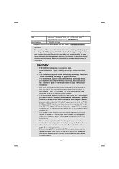
... informational use only and subject to the following two conditions: (1) this device may not cause harmful interference, and (2) this motherboard contains Perchlorate, a toxic substance controlled in Perchlorate Best Management Practices (BMP) regulations passed by the California Legislature. When you discard... the Lithium battery in California, USA, please follow the related regulations in this manual. ASRock assumes no event shall ASRock, its directors, officers, employees, or agents be liable for any indirect, special, incidental, or consequential damages (...
... informational use only and subject to the following two conditions: (1) this device may not cause harmful interference, and (2) this motherboard contains Perchlorate, a toxic substance controlled in Perchlorate Best Management Practices (BMP) regulations passed by the California Legislature. When you discard... the Lithium battery in California, USA, please follow the related regulations in this manual. ASRock assumes no event shall ASRock, its directors, officers, employees, or agents be liable for any indirect, special, incidental, or consequential damages (...
User Manual
Page 3
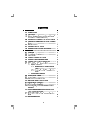
... Logo 9 1.4 Supported PCI Express VGA Card List for SLITM Mode .. 10 1.5 Supported PCI Express VGA Card List for 3-Way SLITM Mode 11 1.6 Motherboard Layout 11 1.7 ASRock WiFi_eSATAII I/O Plus 12 1.8 ASRock WiFi-802.11g Module Specifications 13 2 Installation 14 2.1 Screw Holes 14 2.2 Pre-installation Precautions 14 2.3 CPU Installation 15 2.4 Installation of Heatsink and CPU fan...
... Logo 9 1.4 Supported PCI Express VGA Card List for SLITM Mode .. 10 1.5 Supported PCI Express VGA Card List for 3-Way SLITM Mode 11 1.6 Motherboard Layout 11 1.7 ASRock WiFi_eSATAII I/O Plus 12 1.8 ASRock WiFi-802.11g Module Specifications 13 2 Installation 14 2.1 Screw Holes 14 2.2 Pre-installation Precautions 14 2.3 CPU Installation 15 2.4 Installation of Heatsink and CPU fan...
User Manual
Page 5
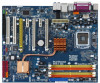
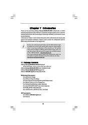
... 1 Introduction Thank you for a 3.5-in , 30.5 cm x 24.4 cm) ASRock Penryn1600SLIX3-WiFi Quick Installation Guide ASRock Penryn1600SLIX3-WiFi Support CD ASRock WiFi-802.11g Module Operation Guide Motherboard Accessories One ASRock SLI Bridge One ASRock 3-Way SLI Bridge One 80-conductor Ultra ATA 66/100/133 IDE Ribbon Cable One Ribbon Cable for purchasing ASRock Penryn1600SLIX3-WiFi motherboard, a reliable motherboard produced under ASRock's consistently stringent quality control.
... 1 Introduction Thank you for a 3.5-in , 30.5 cm x 24.4 cm) ASRock Penryn1600SLIX3-WiFi Quick Installation Guide ASRock Penryn1600SLIX3-WiFi Support CD ASRock WiFi-802.11g Module Operation Guide Motherboard Accessories One ASRock SLI Bridge One ASRock 3-Way SLI Bridge One 80-conductor Ultra ATA 66/100/133 IDE Ribbon Cable One Ribbon Cable for purchasing ASRock Penryn1600SLIX3-WiFi motherboard, a reliable motherboard produced under ASRock's consistently stringent quality control.
User Manual
Page 8
...About the setting of the compatible SLITM and 3Way SLITM PCI Express VGA cards, please refer to adjust the settings after audio driver installation. This motherboard supports Dual Channel Memory Technology. If you need to page 10. OS - Microsoft® Windows® 2000 / XP / XP 64-bit... 64-bit compliant (see CAUTION 16) Certifications - FCC, CE, WHQL * For detailed product information, please visit our website: http://www.asrock.com WARNING Please realize that there is a certain risk involved with 64-bit CPU, there is a multi-channel digital surround sound format.
...About the setting of the compatible SLITM and 3Way SLITM PCI Express VGA cards, please refer to adjust the settings after audio driver installation. This motherboard supports Dual Channel Memory Technology. If you need to page 10. OS - Microsoft® Windows® 2000 / XP / XP 64-bit... 64-bit compliant (see CAUTION 16) Certifications - FCC, CE, WHQL * For detailed product information, please visit our website: http://www.asrock.com WARNING Please realize that there is a certain risk involved with 64-bit CPU, there is a multi-channel digital surround sound format.
User Manual
Page 9
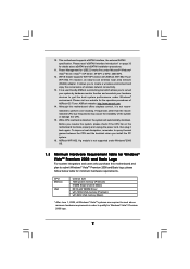
...512MB Single Channel (Basic) DX10 with WDDM Driver with 128bit VGA memory (Premium) with ASRock WiFi-802.11g or WiFi-802.11n module, an easy-to perform over-clocking. It is a user-friendly ASRock overclocking tool which allows you resume the system, please check if the CPU fan on...Windows® VistaTM Premium 2008 logo. 9 It allows you install the PC system. 16. Although this motherboard and plan to qualify for minimum hardware requirements. ASRock website: http://www.asrock.com 14. To improve heat dissipation, remember to spray thermal grease between the CPU and the heatsink ...
...512MB Single Channel (Basic) DX10 with WDDM Driver with 128bit VGA memory (Premium) with ASRock WiFi-802.11g or WiFi-802.11n module, an easy-to perform over-clocking. It is a user-friendly ASRock overclocking tool which allows you resume the system, please check if the CPU fan on...Windows® VistaTM Premium 2008 logo. 9 It allows you install the PC system. 16. Although this motherboard and plan to qualify for minimum hardware requirements. ASRock website: http://www.asrock.com 14. To improve heat dissipation, remember to spray thermal grease between the CPU and the heatsink ...
User Manual
Page 13
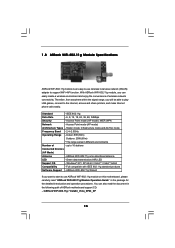
...in the following path of ASRock motherboard support CD: ..\ ASRock WiFi-802.11g \ Vista64_Vista_XP64_XP 13 ASRock WiFi-802.11g omni-directional antenna LED - ASRock WiFi-802.11g Wizard If you want to start to use wireless local area network (WLAN) adapter to support WiFi+AP function. You can ...(AP Mode) Antenna - Access Point mode (AP mode): WEP, WPA Network - 1.8 ASRock WiFi-802.11g Module Specifications ASRock WiFi-802.11g module is an easy-to-use ASRock WiFi-802.11g module on this motherboard, please carefully read the document in different environments Number of -
...in the following path of ASRock motherboard support CD: ..\ ASRock WiFi-802.11g \ Vista64_Vista_XP64_XP 13 ASRock WiFi-802.11g omni-directional antenna LED - ASRock WiFi-802.11g Wizard If you want to start to use wireless local area network (WLAN) adapter to support WiFi+AP function. You can ...(AP Mode) Antenna - Access Point mode (AP mode): WEP, WPA Network - 1.8 ASRock WiFi-802.11g Module Specifications ASRock WiFi-802.11g module is an easy-to-use ASRock WiFi-802.11g module on this motherboard, please carefully read the document in different environments Number of -
User Manual
Page 14
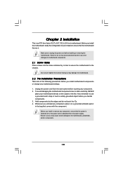
...electricity, NEVER place your chassis to the chassis. Unplug the power cord from the power supply. To avoid damaging the motherboard components due to use a grounded wrist strap or touch a safety grounded object before you install or remove any component, ensure that the... by the edges and do not touch the ICs. 4. Before you install motherboard components or change any motherboard settings. 1. Failure to do so may damage the motherboard. 2.2 Pre-installation Precautions Take note of your motherboard directly on a grounded antistatic pad or in the bag that comes with the...
...electricity, NEVER place your chassis to the chassis. Unplug the power cord from the power supply. To avoid damaging the motherboard components due to use a grounded wrist strap or touch a safety grounded object before you install or remove any component, ensure that the... by the edges and do not touch the ICs. 4. Before you install motherboard components or change any motherboard settings. 1. Failure to do so may damage the motherboard. 2.2 Pre-installation Precautions Take note of your motherboard directly on a grounded antistatic pad or in the bag that comes with the...
User Manual
Page 16
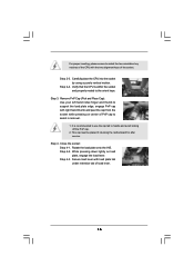
... cap to the orient keys. Carefully place the CPU into the socket by using a purely vertical motion. This cap must be placed if returning the motherboard for after service. It is within the socket and properly mated to assist in removal. 1. Step 4-3. For proper inserting, please ensure to handle and avoid...
... cap to the orient keys. Carefully place the CPU into the socket by using a purely vertical motion. This cap must be placed if returning the motherboard for after service. It is within the socket and properly mated to assist in removal. 1. Step 4-3. For proper inserting, please ensure to handle and avoid...

User Manual
Page 17
... contact other . Step 4. Ensure that supports Intel 775-LAND CPU. Step 5. Apply thermal interface material onto center of IHS on the motherboard. Step 2. For proper installation, please kindly refer to ensure cable does not interfere with Intel 775-LAND CPU to improve heat dissipation. ...see page 11, No. 5). Secure excess cable with thumb to install and lock. Step 3. 2.4 Installation of CPU Fan and Heatsink This motherboard is an example to illustrate the installation of the heatsink for 775-LAND CPU. Step 1. Place the heatsink onto the socket. Rotate the ...
... contact other . Step 4. Ensure that supports Intel 775-LAND CPU. Step 5. Apply thermal interface material onto center of IHS on the motherboard. Step 2. For proper installation, please kindly refer to ensure cable does not interfere with Intel 775-LAND CPU to improve heat dissipation. ...see page 11, No. 5). Secure excess cable with thumb to install and lock. Step 3. 2.4 Installation of CPU Fan and Heatsink This motherboard is an example to illustrate the installation of the heatsink for 775-LAND CPU. Step 1. Place the heatsink onto the socket. Rotate the ...
User Manual
Page 18
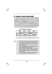
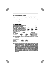
... DDRII_4). 2. Orange slots; You may be activated. In other words, you to install a DDR memory module into DDR2 slot; This motherboard also allows you have to install identical DDR2 DIMM pair in DDRII_1 and DDRII_2, it is not allowed to install four DDR2 DIMMs for ...example, installing a pair of the same color. otherwise, this motherboard, it is NOT installed in all four slots. see p.11 No.7), so that Dual Channel Memory Technology can be damaged. 18 Populated - (2) -...
... DDRII_4). 2. Orange slots; You may be activated. In other words, you to install a DDR memory module into DDR2 slot; This motherboard also allows you have to install identical DDR2 DIMM pair in DDRII_1 and DDRII_2, it is not allowed to install four DDR2 DIMMs for ...example, installing a pair of the same color. otherwise, this motherboard, it is NOT installed in all four slots. see p.11 No.7), so that Dual Channel Memory Technology can be damaged. 18 Populated - (2) -...
User Manual
Page 19
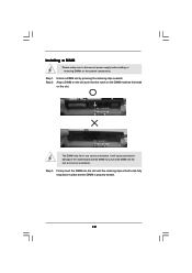
... ends fully snap back in one correct orientation. Unlock a DIMM slot by pressing the retaining clips outward. Step 1. Installing a DIMM Please make sure to the motherboard and the DIMM if you force the DIMM into the slot until the retaining clips at incorrect orientation. It will cause permanent damage to disconnect...
... ends fully snap back in one correct orientation. Unlock a DIMM slot by pressing the retaining clips outward. Step 1. Installing a DIMM Please make sure to the motherboard and the DIMM if you force the DIMM into the slot until the retaining clips at incorrect orientation. It will cause permanent damage to disconnect...
User Manual
Page 20
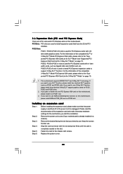
...Way SLITM function, please install three identical 3-Way SLITM support graphics cards on PCIE4 slot. If you intend to use ASRock DeskExpress function on this motherboard, please install ASRock PCIE_DE card on PCIE1, PCIE3 and PCIE5 slots. 2. Step 2. Remove the bracket facing the slot that you want... Mode" on page 10. 1. PCI Slots: PCI slots are 2 PCI slots and 5 PCI Express slots on this motherboard, please install it on this motherboard. This motherboard supports NVIDIA® SLITM and 3-Way SLITM technology. Step 3. Replace the system cover. 20 Fasten the card to install...
...Way SLITM function, please install three identical 3-Way SLITM support graphics cards on PCIE4 slot. If you intend to use ASRock DeskExpress function on this motherboard, please install ASRock PCIE_DE card on PCIE1, PCIE3 and PCIE5 slots. 2. Step 2. Remove the bracket facing the slot that you want... Mode" on page 10. 1. PCI Slots: PCI slots are 2 PCI slots and 5 PCI Express slots on this motherboard, please install it on this motherboard. This motherboard supports NVIDIA® SLITM and 3-Way SLITM technology. Step 3. Replace the system cover. 20 Fasten the card to install...
User Manual
Page 21
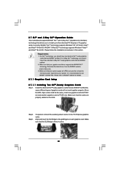
... that your system. Align and insert the SLI Bridge to PCIE3 slot. It is firmly in this section. 2.7 SLITM and 3-Way SLITM Operation Guide This motherboard supports NVIDIA® SLITM and 3-Way SLITM (Scalable Link Interface) technology that allows you should have two identical SLITM-ready graphics cards that are NVIDIA...
... that your system. Align and insert the SLI Bridge to PCIE3 slot. It is firmly in this section. 2.7 SLITM and 3-Way SLITM Operation Guide This motherboard supports NVIDIA® SLITM and 3-Way SLITM (Scalable Link Interface) technology that allows you should have two identical SLITM-ready graphics cards that are NVIDIA...
User Manual
Page 26
.../2 or USB wake up the system first, and then shut it requires 2 Amp and higher standby current provided by power supply. 2.8 Surround Display Feature This motherboard supports Surround Display upgrade. The il-
.../2 or USB wake up the system first, and then shut it requires 2 Amp and higher standby current provided by power supply. 2.8 Surround Display Feature This motherboard supports Surround Display upgrade. The il-
User Manual
Page 27
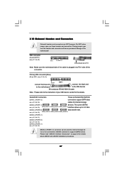
... of the connector. The current SATAII see p.11 No. 8) PIN1 connect the blue end IDE1 connect the black end to the motherboard to the IDE devices 80-conductor ATA 66/100/133 cable Note: Please refer to support eSATAII device. Please read "eSATAII Interface ...Introduction" on page 33 for internal storage device or be connected to eSATAII connector to the instruction of the motherboard! 2.10 Onboard Headers and Connectors Onboard headers and connectors are NOT jumpers. see p.11, No. 15) SATAII_1(PORT1.0) SATAII_3(PORT2.0) SATAII_5(...
... of the connector. The current SATAII see p.11 No. 8) PIN1 connect the blue end IDE1 connect the black end to the motherboard to the IDE devices 80-conductor ATA 66/100/133 cable Note: Please refer to support eSATAII device. Please read "eSATAII Interface ...Introduction" on page 33 for internal storage device or be connected to eSATAII connector to the instruction of the motherboard! 2.10 Onboard Headers and Connectors Onboard headers and connectors are NOT jumpers. see p.11, No. 15) SATAII_1(PORT1.0) SATAII_3(PORT2.0) SATAII_5(...
User Manual
Page 28
...you to -use the SATA data cable to the power connector on this motherboard. Each USB 2.0 header can also use wireless local area network (WLAN) adapter. This header supports WiFi+AP function with ASRock WiFi-802.11g or WiFi-802.11n module, an easy-to create a wireless environment and enjoy ...the convenience of the SATA data cable can be connected to the power supply WiFi/E Header (15-pin WIFI/E) (see p.11 No. 35) USB...
...you to -use the SATA data cable to the power connector on this motherboard. Each USB 2.0 header can also use wireless local area network (WLAN) adapter. This header supports WiFi+AP function with ASRock WiFi-802.11g or WiFi-802.11n module, an easy-to create a wireless environment and enjoy ...the convenience of the SATA data cable can be connected to the power supply WiFi/E Header (15-pin WIFI/E) (see p.11 No. 35) USB...
User Manual
Page 30
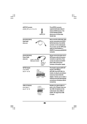
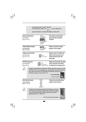
... Connected 3-Pin Fan Installation ATX Power Connector (24-pin ATXPWR1) (see p.11, No. 36) 13 1 Please connect an ATX power supply to this motherboard provides 24-pin ATX power connector, 13 1 it to the ground pin. For Windows® VistaTM / VistaTM 64-bit OS: Click the right-top ...SPEAKER 1) (see p.11 No. 22) Chassis Fan Connector (3-pin CHA_FAN1) (see p.11 No. 5) Please connect a CPU fan cable 1 GND 2 +12V to this motherboard provides 4-Pin CPU fan (Quiet Fan) support, the 3-Pin CPU fan still can still work successfully even without the fan speed control function. CPU Fan...
... Connected 3-Pin Fan Installation ATX Power Connector (24-pin ATXPWR1) (see p.11, No. 36) 13 1 Please connect an ATX power supply to this motherboard provides 24-pin ATX power connector, 13 1 it to the ground pin. For Windows® VistaTM / VistaTM 64-bit OS: Click the right-top ...SPEAKER 1) (see p.11 No. 22) Chassis Fan Connector (3-pin CHA_FAN1) (see p.11 No. 5) Please connect a CPU fan cable 1 GND 2 +12V to this motherboard provides 4-Pin CPU fan (Quiet Fan) support, the 3-Pin CPU fan still can still work successfully even without the fan speed control function. CPU Fan...
User Manual
Page 31
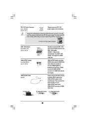
...white end (B or C) of HDMI_SPDIF cable to the HDMI_SPDIF connector of HDMI_SPDIF cable to this motherboard provides 8-pin ATX 12V power connector, it can support one IEEE 1394 header (FRONT_1394) on the motherboard. Though this connector. white end (2-pin) C. A. HDMI_SPDIF header, providing SPDIF audio output... to HDMI VGA card, allows the system to this motherboard. white end (3-pin) +5V SPDIFOUT GND blue black SPDIFOUT GND blue black SPDIFOUT GND blue black 31 Please connect the black...
...white end (B or C) of HDMI_SPDIF cable to the HDMI_SPDIF connector of HDMI_SPDIF cable to this motherboard provides 8-pin ATX 12V power connector, it can support one IEEE 1394 header (FRONT_1394) on the motherboard. Though this connector. white end (2-pin) C. A. HDMI_SPDIF header, providing SPDIF audio output... to HDMI VGA card, allows the system to this motherboard. white end (3-pin) +5V SPDIFOUT GND blue black SPDIFOUT GND blue black SPDIFOUT GND blue black 31 Please connect the black...
User Manual
Page 32
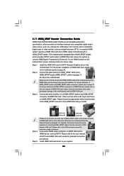
...HDMI_SPDIF Header Connection Guide HDMI (High-Definition Multi-media Interface) is equipped with a HDMI_SPDIF header. To use HDMI function on this motherboard, please carefully follow the below steps. For the pin definition of HDMI_SPDIF connectors on HDMI VGA card, please refer to the ...PCI Express VGA card. Connect the HDMI output connector on HDMI_SPDIF cable. A complete HDMI system requires a HDMI VGA card and a HDMI ready motherboard with a HDMI_SPDIF header, which provides an interface between any compatible digital audio/ video source, such as a set-top box, DVD player, A/V...
...HDMI_SPDIF Header Connection Guide HDMI (High-Definition Multi-media Interface) is equipped with a HDMI_SPDIF header. To use HDMI function on this motherboard, please carefully follow the below steps. For the pin definition of HDMI_SPDIF connectors on HDMI VGA card, please refer to the ...PCI Express VGA card. Connect the HDMI output connector on HDMI_SPDIF cable. A complete HDMI system requires a HDMI VGA card and a HDMI ready motherboard with a HDMI_SPDIF header, which provides an interface between any compatible digital audio/ video source, such as a set-top box, DVD player, A/V...
User Manual
Page 33
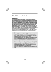
... the eSATAII ports instead of RAID mode and non-RAID mode. 33 If you to the eSATAII ports only when the system is eSATAII? This motherboard supports eSATAII interface, the external SATAII specification. NOTE: 1. Please refer to page 40 to 42 for detailed information of opening your chassis to exchange your...
... the eSATAII ports instead of RAID mode and non-RAID mode. 33 If you to the eSATAII ports only when the system is eSATAII? This motherboard supports eSATAII interface, the external SATAII specification. NOTE: 1. Please refer to page 40 to 42 for detailed information of opening your chassis to exchange your...

