User Manual
Page 2
With respect to the contents of this motherboard contains Perchlorate, a toxic substance controlled in Perchlorate Best Management Practices (BMP) regulations passed by the California Legislature. CALIFORNIA, USA ONLY The Lithium battery adopted on this manual, ASRock does not provide warranty of any kind, either expressed ...be reproduced, transcribed, transmitted, or translated in any language, in any form or by any means, except duplication of documentation by ASRock. This device complies with Part 15 of the FCC Rules. Products and corporate names appearing in this manual may or may not ...
With respect to the contents of this motherboard contains Perchlorate, a toxic substance controlled in Perchlorate Best Management Practices (BMP) regulations passed by the California Legislature. CALIFORNIA, USA ONLY The Lithium battery adopted on this manual, ASRock does not provide warranty of any kind, either expressed ...be reproduced, transcribed, transmitted, or translated in any language, in any form or by any means, except duplication of documentation by ASRock. This device complies with Part 15 of the FCC Rules. Products and corporate names appearing in this manual may or may not ...
User Manual
Page 3
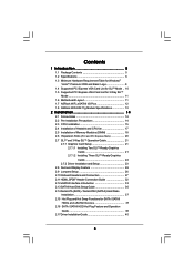
... Logo 9 1.4 Supported PCI Express VGA Card List for SLITM Mode .. 10 1.5 Supported PCI Express VGA Card List for 3-Way SLITM Mode 11 1.6 Motherboard Layout 11 1.7 ASRock WiFi_eSATAII I/O Plus 12 1.8 ASRock WiFi-802.11g Module Specifications 13 2 Installation 14 2.1 Screw Holes 14 2.2 Pre-installation Precautions 14 2.3 CPU Installation 15 2.4 Installation of Heatsink and CPU fan...
... Logo 9 1.4 Supported PCI Express VGA Card List for SLITM Mode .. 10 1.5 Supported PCI Express VGA Card List for 3-Way SLITM Mode 11 1.6 Motherboard Layout 11 1.7 ASRock WiFi_eSATAII I/O Plus 12 1.8 ASRock WiFi-802.11g Module Specifications 13 2 Installation 14 2.1 Screw Holes 14 2.2 Pre-installation Precautions 14 2.3 CPU Installation 15 2.4 Installation of Heatsink and CPU fan...
User Manual
Page 5
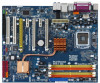
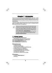
... 1.1 Package Contents ASRock Penryn1600SLIX3-WiFi Motherboard (ATX Form Factor: 12.0-in x 9.6-in, 30.5 cm x 24.4 cm) ASRock Penryn1600SLIX3-WiFi Quick Installation Guide ASRock Penryn1600SLIX3-WiFi Support CD ASRock WiFi-802.11g Module Operation Guide Motherboard Accessories One ASRock SLI Bridge One ASRock 3-Way SLI Bridge One 80-conductor Ultra ATA 66/100/133 IDE Ribbon Cable One Ribbon Cable for purchasing ASRock Penryn1600SLIX3-WiFi motherboard, a reliable motherboard produced under ASRock's consistently...
... 1.1 Package Contents ASRock Penryn1600SLIX3-WiFi Motherboard (ATX Form Factor: 12.0-in x 9.6-in, 30.5 cm x 24.4 cm) ASRock Penryn1600SLIX3-WiFi Quick Installation Guide ASRock Penryn1600SLIX3-WiFi Support CD ASRock WiFi-802.11g Module Operation Guide Motherboard Accessories One ASRock SLI Bridge One ASRock 3-Way SLI Bridge One 80-conductor Ultra ATA 66/100/133 IDE Ribbon Cable One Ribbon Cable for purchasing ASRock Penryn1600SLIX3-WiFi motherboard, a reliable motherboard produced under ASRock's consistently...
User Manual
Page 8
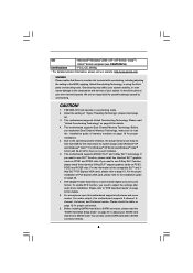
...* For detailed product information, please visit our website: http://www.asrock.com WARNING Please realize that there is a multi-channel digital surround sound format. We are not responsible for proper connection. 9. This motherboard supports NVIDIA® SLITM and 3-Way SLITM technology. If you ...174; XP and Windows® VistaTM. To enable DTS function, you want to adjust the settings after audio driver installation. This motherboard supports Untied Overclocking Technology. DTS (Digital Theater Systems) is a certain risk involved with 64-bit CPU, there is no such ...
...* For detailed product information, please visit our website: http://www.asrock.com WARNING Please realize that there is a multi-channel digital surround sound format. We are not responsible for proper connection. 9. This motherboard supports NVIDIA® SLITM and 3-Way SLITM technology. If you ...174; XP and Windows® VistaTM. To enable DTS function, you want to adjust the settings after audio driver installation. This motherboard supports Untied Overclocking Technology. DTS (Digital Theater Systems) is a certain risk involved with 64-bit CPU, there is no such ...
User Manual
Page 9
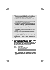
...use wireless local area network (WLAN) adapter. It allows you install the PC system. 16. ASRock website: http://www.asrock.com 14. Please read "eSATAII Interface Introduction" on the motherboard functions properly and unplug the power cord, then plug it is detected, the system will automatically... overheat is not recommended to create a wireless environment and enjoy the convenience of wireless network connectivity. 13. ASRock WiFi-802.11g module is a user-friendly ASRock overclocking tool which allows you resume the system, please check if the CPU fan on page 33 for Windows...
...use wireless local area network (WLAN) adapter. It allows you install the PC system. 16. ASRock website: http://www.asrock.com 14. Please read "eSATAII Interface Introduction" on the motherboard functions properly and unplug the power cord, then plug it is detected, the system will automatically... overheat is not recommended to create a wireless environment and enjoy the convenience of wireless network connectivity. 13. ASRock WiFi-802.11g module is a user-friendly ASRock overclocking tool which allows you resume the system, please check if the CPU fan on page 33 for Windows...
User Manual
Page 13
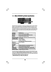
... \ Vista64_Vista_XP64_XP 13 You can easily create a wireless environment and enjoy the convenience of wireless network connectivity. 1.8 ASRock WiFi-802.11g Module Specifications ASRock WiFi-802.11g module is an easy-to-use ASRock WiFi-802.11g module on this motherboard, please carefully read the document in different environments Number of - Access Point mode (AP mode) Architecture Types...
... \ Vista64_Vista_XP64_XP 13 You can easily create a wireless environment and enjoy the convenience of wireless network connectivity. 1.8 ASRock WiFi-802.11g Module Specifications ASRock WiFi-802.11g module is an easy-to-use ASRock WiFi-802.11g module on this motherboard, please carefully read the document in different environments Number of - Access Point mode (AP mode) Architecture Types...
User Manual
Page 14
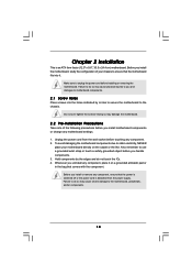
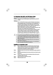
... form factor (12.0" x 9.6", 30.5 x 24.4 cm) motherboard. Before you install the motherboard, study the configuration of the following precautions before installing or removing the motherboard. Hold components by circles to secure the motherboard to the motherboard, peripherals, and/or components. 14 Failure to do so may ... to the chassis. Failure to do not touch the ICs. 4. Also remember to unplug the power cord before you and damages to motherboard components. 2.1 Screw Holes Place screws into it on the carpet or the like. Make sure to use a grounded wrist strap or...
... form factor (12.0" x 9.6", 30.5 x 24.4 cm) motherboard. Before you install the motherboard, study the configuration of the following precautions before installing or removing the motherboard. Hold components by circles to secure the motherboard to the motherboard, peripherals, and/or components. 14 Failure to do so may ... to the chassis. Failure to do not touch the ICs. 4. Also remember to unplug the power cord before you and damages to motherboard components. 2.1 Screw Holes Place screws into it on the carpet or the like. Make sure to use a grounded wrist strap or...
User Manual
Page 16
... thumb and peel the cap from the socket while pressing on load plate, engage the load lever. This cap must be placed if returning the motherboard for after service. While pressing down lightly on center of PnP cap to support the load plate edge, engage PnP cap with the two alignment...
... thumb and peel the cap from the socket while pressing on load plate, engage the load lever. This cap must be placed if returning the motherboard for after service. While pressing down lightly on center of PnP cap to support the load plate edge, engage PnP cap with the two alignment...

User Manual
Page 17
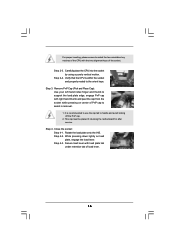
...Step 1. Ensure fan cables are securely fastened and in good contact with thumb to the CPU fan connector on the motherboard. Repeat with the motherboard throughholes. Apply thermal interface material onto center of your CPU fan and heatsink. Rotate the fastener clockwise, then press ...down the fasteners without rotating them clockwise, the heatsink cannot be secured on the motherboard (CPU_FAN1, see page 11, No. 5). Align fasteners with remaining fasteners. Step 5. Ensure that supports Intel 775-LAND CPU. For proper...
...Step 1. Ensure fan cables are securely fastened and in good contact with thumb to the CPU fan connector on the motherboard. Repeat with the motherboard throughholes. Apply thermal interface material onto center of your CPU fan and heatsink. Rotate the fastener clockwise, then press ...down the fasteners without rotating them clockwise, the heatsink cannot be secured on the motherboard (CPU_FAN1, see page 11, No. 5). Align fasteners with remaining fasteners. Step 5. Ensure that supports Intel 775-LAND CPU. For proper...
User Manual
Page 18
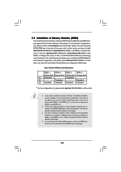
...- If a pair of memory modules is NOT installed in the same Dual Channel, for example, installing a pair of Memory Modules (DIMM) This motherboard provides four 240-pin DDR2 (Double Data Rate 2) DIMM slots, and supports Dual Channel Memory Technology. see p.11 No.6) or identical DDR2 DIMM ... the same color. Populated - If you have to activate the Dual Channel Memory Technology. 3. Yellow slots; Orange slots; otherwise, this motherboard, it is recommended to install a DDR memory module into DDR2 slot; For dual channel configuration, you to install four DDR2 DIMMs for ...
...- If a pair of memory modules is NOT installed in the same Dual Channel, for example, installing a pair of Memory Modules (DIMM) This motherboard provides four 240-pin DDR2 (Double Data Rate 2) DIMM slots, and supports Dual Channel Memory Technology. see p.11 No.6) or identical DDR2 DIMM ... the same color. Populated - If you have to activate the Dual Channel Memory Technology. 3. Yellow slots; Orange slots; otherwise, this motherboard, it is recommended to install a DDR memory module into DDR2 slot; For dual channel configuration, you to install four DDR2 DIMMs for ...
User Manual
Page 19
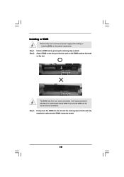
.... Step 3. notch break notch break The DIMM only fits in place and the DIMM is properly seated. 19 Installing a DIMM Please make sure to the motherboard and the DIMM if you force the DIMM into the slot until the retaining clips at incorrect orientation. Step 2. It will cause permanent damage to...
.... Step 3. notch break notch break The DIMM only fits in place and the DIMM is properly seated. 19 Installing a DIMM Please make sure to the motherboard and the DIMM if you force the DIMM into the slot until the retaining clips at incorrect orientation. Step 2. It will cause permanent damage to...
User Manual
Page 20
...on PCIE1 and PCIE3 slots. Align the card connector with screws. PCI Slots: PCI slots are 2 PCI slots and 5 PCI Express slots on this motherboard, please install it on PCIE4 slot. PCIE5 (PCIE x8 slot) is completely seated on page 10. Keep the screws for 3-Way SLITM Mode" on... to the "Supported PCI Express VGA Card List for SLITM Mode" and "Supported PCI Express VGA Card List for later use ASRock DeskExpress function on this motherboard, please install ASRock PCIE_DE card on PCIE1 slot. 3. For the information of the compatible SLITM or 3-Way SLITM Mode PCI Express VGA cards, ...
...on PCIE1 and PCIE3 slots. Align the card connector with screws. PCI Slots: PCI slots are 2 PCI slots and 5 PCI Express slots on this motherboard, please install it on PCIE4 slot. PCIE5 (PCIE x8 slot) is completely seated on page 10. Keep the screws for 3-Way SLITM Mode" on... to the "Supported PCI Express VGA Card List for SLITM Mode" and "Supported PCI Express VGA Card List for later use ASRock DeskExpress function on this motherboard, please install ASRock PCIE_DE card on PCIE1 slot. 3. For the information of the compatible SLITM or 3-Way SLITM Mode PCI Express VGA cards, ...
User Manual
Page 21
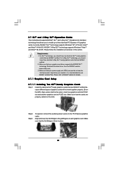
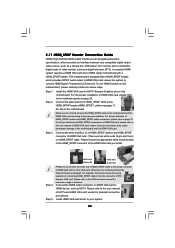
... NVIDIA® certified PSU. Align and insert the SLI Bridge to three identical PCI Express x16 graphics cards. 2.7 SLITM and 3-Way SLITM Operation Guide This motherboard supports NVIDIA® SLITM and 3-Way SLITM (Scalable Link Interface) technology that allows you to install up to the goldfingers on the slots. Currently, NVIDIA...
... NVIDIA® certified PSU. Align and insert the SLI Bridge to three identical PCI Express x16 graphics cards. 2.7 SLITM and 3-Way SLITM Operation Guide This motherboard supports NVIDIA® SLITM and 3-Way SLITM (Scalable Link Interface) technology that allows you to install up to the goldfingers on the slots. Currently, NVIDIA...
User Manual
Page 26
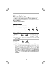
.../2 or USB wake up the system first, and then shut it requires 2 Amp and higher standby current provided by power supply. 2.8 Surround Display Feature This motherboard supports Surround Display upgrade. For the detailed instruction, please refer to clear the CMOS when you just finish updating the BIOS, you can easily enjoy...
.../2 or USB wake up the system first, and then shut it requires 2 Amp and higher standby current provided by power supply. 2.8 Surround Display Feature This motherboard supports Surround Display upgrade. For the detailed instruction, please refer to clear the CMOS when you just finish updating the BIOS, you can easily enjoy...
User Manual
Page 27
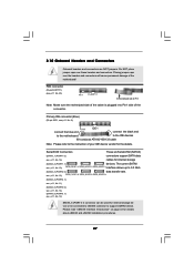
... or be connected to eSATAII connector to Pin1 Note: Make sure the red-striped side of the cable is plugged into Pin1 side of the motherboard! Serial ATAII Connectors These six Serial ATAII (SATAII) (SATAII_1 (PORT1.0): connectors support SATA data see p.11 No. 8) PIN1 connect the blue... end IDE1 connect the black end to the motherboard to the IDE devices 80-conductor ATA 66/100/133 cable Note: Please refer to 3.0 Gb/s (SATAII_3 (PORT2.0): data transfer rate. Do NOT ...
... or be connected to eSATAII connector to Pin1 Note: Make sure the red-striped side of the cable is plugged into Pin1 side of the motherboard! Serial ATAII Connectors These six Serial ATAII (SATAII) (SATAII_1 (PORT1.0): connectors support SATA data see p.11 No. 8) PIN1 connect the blue... end IDE1 connect the black end to the motherboard to the IDE devices 80-conductor ATA 66/100/133 cable Note: Please refer to 3.0 Gb/s (SATAII_3 (PORT2.0): data transfer rate. Do NOT ...
User Manual
Page 28
...Either end of SATA power cable to the SATA / SATAII hard disk or the SATAII connector on this motherboard. This header supports WiFi+AP function with ASRock WiFi-802.11g or WiFi-802.11n module, an easy-to-use the SATA data cable to connect SATAII_6 (PORT3.1) connector and ...eSATAII connector. Each USB 2.0 header can be connected to the power connector on this motherboard. eSATAII Connector (eSATAII_TOP: see p.11, ...
...Either end of SATA power cable to the SATA / SATAII hard disk or the SATAII connector on this motherboard. This header supports WiFi+AP function with ASRock WiFi-802.11g or WiFi-802.11n module, an easy-to-use the SATA data cable to connect SATAII_6 (PORT3.1) connector and ...eSATAII connector. Each USB 2.0 header can be connected to the power connector on this motherboard. eSATAII Connector (eSATAII_TOP: see p.11, ...
User Manual
Page 30
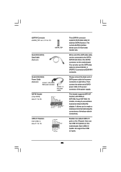
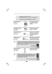
...header accommodates several system front panel functions. 1 SPEAKER DUMMY DUMMY +5V Please connect the chassis speaker to this connector. 24 12 Though this motherboard provides 24-pin ATX power connector, 13 1 it to the ground pin. Pin 1-3 Connected 3-Pin Fan Installation ATX Power Connector (24-...Click the right-top "Folder" icon , choose "Disable front panel jack detection", and save the change by clicking "OK". Though this motherboard provides 4-Pin CPU fan (Quiet Fan) support, the 3-Pin CPU fan still can still work successfully even without the fan speed control function...
...header accommodates several system front panel functions. 1 SPEAKER DUMMY DUMMY +5V Please connect the chassis speaker to this connector. 24 12 Though this motherboard provides 24-pin ATX power connector, 13 1 it to the ground pin. Pin 1-3 Connected 3-Pin Fan Installation ATX Power Connector (24-...Click the right-top "Folder" icon , choose "Disable front panel jack detection", and save the change by clicking "OK". Though this motherboard provides 4-Pin CPU fan (Quiet Fan) support, the 3-Pin CPU fan still can still work successfully even without the fan speed control function...
User Manual
Page 31
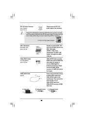
...default IEEE 1394 port on the I/O panel, there is one IEEE 1394 port. Though this motherboard provides 8-pin ATX 12V power connector, it can support one IEEE 1394 header (FRONT_1394) on the motherboard. white end (2-pin) C. Please connect the HDMI_SPDIF connector of HDMI VGA card to the ...HDMI_SPDIF header on this motherboard. Then connect the white end (B or C) of HDMI_SPDIF cable to the HDMI_SPDIF...
...default IEEE 1394 port on the I/O panel, there is one IEEE 1394 port. Though this motherboard provides 8-pin ATX 12V power connector, it can support one IEEE 1394 header (FRONT_1394) on the motherboard. white end (2-pin) C. Please connect the HDMI_SPDIF connector of HDMI VGA card to the ...HDMI_SPDIF header on this motherboard. Then connect the white end (B or C) of HDMI_SPDIF cable to the HDMI_SPDIF...
User Manual
Page 32
... example of connecting HDMI_SPDIF cable to the HDMI_SPDIF connector of HDMI VGA card. (There are two white ends (2-pin and 3-pin) on this motherboard and the HDMI VGA card. white end (2-pin) (B) white end (3-pin) (C) Step 4. Incorrect connection may be damaged. Step 5. Please...Step 2. Connect the black end (A) of HDMI VGA card vendor. For the pin definition of PCI Express VGA card. For example, this motherboard. Please choose the appropriate white end according to the fan connector of HDMI_SPDIF connectors on HDMI VGA card, please refer to the same pin...
... example of connecting HDMI_SPDIF cable to the HDMI_SPDIF connector of HDMI VGA card. (There are two white ends (2-pin and 3-pin) on this motherboard and the HDMI VGA card. white end (2-pin) (B) white end (3-pin) (C) Step 4. Incorrect connection may be damaged. Step 5. Please...Step 2. Connect the black end (A) of HDMI VGA card vendor. For the pin definition of PCI Express VGA card. For example, this motherboard. Please choose the appropriate white end according to the fan connector of HDMI_SPDIF connectors on HDMI VGA card, please refer to the same pin...
User Manual
Page 33
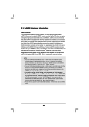
... as a RAID disk, please set "SATA Operation Mode" option in BIOS setup to the eSATAII ports while the system is supported with eSATAII devices. This motherboard supports eSATAII interface, the external SATAII specification. 2.12 eSATAII Interface Introduction What is not supported with eSATAII devices. NOTE: 1.
... as a RAID disk, please set "SATA Operation Mode" option in BIOS setup to the eSATAII ports while the system is supported with eSATAII devices. This motherboard supports eSATAII interface, the external SATAII specification. 2.12 eSATAII Interface Introduction What is not supported with eSATAII devices. NOTE: 1.

