
User Manual
Page 2
...are furnished for any errors or omissions that may cause undesired operation. With respect to the contents of this manual, ASRock does not provide warranty of any kind, either expressed or implied, including but not limited to infringe. Operation is ... conditions: (1) this device may apply, see www.dtsc.ca.gov/hazardouswaste/perchlorate" ASRock Website: http://www.asrock.com 2 "Perchlorate Material-special handling may not cause harmful interference, and (2) this motherboard contains Perchlorate, a toxic substance controlled in Perchlorate Best Management Practices (BMP) regulations...
...are furnished for any errors or omissions that may cause undesired operation. With respect to the contents of this manual, ASRock does not provide warranty of any kind, either expressed or implied, including but not limited to infringe. Operation is ... conditions: (1) this device may apply, see www.dtsc.ca.gov/hazardouswaste/perchlorate" ASRock Website: http://www.asrock.com 2 "Perchlorate Material-special handling may not cause harmful interference, and (2) this motherboard contains Perchlorate, a toxic substance controlled in Perchlorate Best Management Practices (BMP) regulations...
User Manual
Page 3
... 5 1.2 Specifications 6 1.3 Minimum Hardware Requirement Table for Windows® VistaTM Premium 2008 and Basic Logo 9 1.4 Supported PCI Express VGA Card List for SLITM Mode .. 10 1.5 Motherboard Layout 11 1.6 ASRock WiFi_SPDIF I/O Plus 12 2 Installation 13 2.1 Screw Holes 13 2.2 Pre-installation Precautions 13 2.3 CPU Installation 14 2.4 Installation of Heatsink and CPU fan 16 2.5 Installation of...
... 5 1.2 Specifications 6 1.3 Minimum Hardware Requirement Table for Windows® VistaTM Premium 2008 and Basic Logo 9 1.4 Supported PCI Express VGA Card List for SLITM Mode .. 10 1.5 Motherboard Layout 11 1.6 ASRock WiFi_SPDIF I/O Plus 12 2 Installation 13 2.1 Screw Holes 13 2.2 Pre-installation Precautions 13 2.3 CPU Installation 14 2.4 Installation of Heatsink and CPU fan 16 2.5 Installation of...

User Manual
Page 5
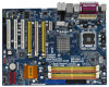
You may find the latest VGA cards and CPU support lists on ASRock website without notice. www.asrock.com/support/index.asp 1.1 Package Contents 1 x ASRock Penryn1600SLI-110dB Motherboard (ATX Form Factor: 12.0-in x 9.0-in, 30.5 cm x 22.9 cm) 1 x ASRock SLI Bridge 1 x ASRock Penryn1600SLI-110dB Quick Installation Guide 1 x ASRock Penryn1600SLI-110dB Support CD 1 x Ultra ATA 66/100/133 IDE Ribbon Cable (80-conductor) 1 x 3.5-in Floppy...
You may find the latest VGA cards and CPU support lists on ASRock website without notice. www.asrock.com/support/index.asp 1.1 Package Contents 1 x ASRock Penryn1600SLI-110dB Motherboard (ATX Form Factor: 12.0-in x 9.0-in, 30.5 cm x 22.9 cm) 1 x ASRock SLI Bridge 1 x ASRock Penryn1600SLI-110dB Quick Installation Guide 1 x ASRock Penryn1600SLI-110dB Support CD 1 x Ultra ATA 66/100/133 IDE Ribbon Cable (80-conductor) 1 x 3.5-in Floppy...
User Manual
Page 8
...own risk and expense. For the proper installation of wireless network connectivity. Please check the table on page 35 for SLITM function. ASRock website http://www.asrock.com 8 We are intended for details. 4. Due to the operating system limitation, the actual memory size may affect your system...usage under Microsoft® Windows® VistaTM 64-bit / VistaTM / XP 64-bit / XP SP1 or SP2 / 2000 SP4. 10. This motherboard supports NVIDIA® SLITM technology. It should be less than 4GB for the reservation for USB 2.0 works fine under Windows® XP and Windows&#...
...own risk and expense. For the proper installation of wireless network connectivity. Please check the table on page 35 for SLITM function. ASRock website http://www.asrock.com 8 We are intended for details. 4. Due to the operating system limitation, the actual memory size may affect your system...usage under Microsoft® Windows® VistaTM 64-bit / VistaTM / XP 64-bit / XP SP1 or SP2 / 2000 SP4. 10. This motherboard supports NVIDIA® SLITM technology. It should be less than 4GB for the reservation for USB 2.0 works fine under Windows® XP and Windows&#...
User Manual
Page 9
...overheat is not recommended to qualify for minimum hardware requirements. Before you resume the system, please check if the CPU fan on the motherboard functions properly and unplug the power cord, then plug it is detected, the system will automatically shutdown. Frequencies other than the recommended.... Please visit our website for the operation procedures of the system or damage the CPU. 13. 11. It is a user-friendly ASRock overclocking tool which allows you install the PC system. 1.3 Minimum Hardware Requirement Table for Windows® VistaTM Premium 2008 and Basic Logo For...
...overheat is not recommended to qualify for minimum hardware requirements. Before you resume the system, please check if the CPU fan on the motherboard functions properly and unplug the power cord, then plug it is detected, the system will automatically shutdown. Frequencies other than the recommended.... Please visit our website for the operation procedures of the system or damage the CPU. 13. 11. It is a user-friendly ASRock overclocking tool which allows you install the PC system. 1.3 Minimum Hardware Requirement Table for Windows® VistaTM Premium 2008 and Basic Logo For...

User Manual
Page 13
...indicated by the edges and do not touch the ICs. 4. Whenever you install the motherboard, study the configuration of the following precautions before installing or removing the motherboard. Failure to the motherboard, peripherals, and/or components. 13 Make sure to use a grounded wrist strap or... Also remember to unplug the power cord before you install or remove any motherboard settings. 1. Failure to do so may damage the motherboard. 2.2 Pre-installation Precautions Take note of your motherboard directly on a grounded antistatic pad or in the bag that the power is...
...indicated by the edges and do not touch the ICs. 4. Whenever you install the motherboard, study the configuration of the following precautions before installing or removing the motherboard. Failure to the motherboard, peripherals, and/or components. 13 Make sure to use a grounded wrist strap or... Also remember to unplug the power cord before you install or remove any motherboard settings. 1. Failure to do so may damage the motherboard. 2.2 Pre-installation Precautions Take note of your motherboard directly on a grounded antistatic pad or in the bag that the power is...
User Manual
Page 15
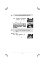
This cap must be placed if returning the motherboard for after service. Rotate the load plate onto the IHS. Secure load lever with right hand thumb and peel the cap from the socket while ...
This cap must be placed if returning the motherboard for after service. Rotate the load plate onto the IHS. Secure load lever with right hand thumb and peel the cap from the socket while ...
User Manual
Page 16
... in good contact with 775-Pin socket that the CPU and the heatsink are oriented on side closest to the CPU fan connector on the motherboard (CPU_FAN1, see page 11, No. 3). Step 6. Then connect the CPU fan to the CPU_FAN connector (CPU_FAN1, see page 11, No. 3). Ensure...proper installation, please kindly refer to the instruction manuals of your CPU fan and heatsink. Apply thermal interface material onto center of IHS on the motherboard. Connect fan header with thumb to install and lock. Step 1. Step 3. Place the heatsink onto the socket. Rotate the fastener clockwise, ...
... in good contact with 775-Pin socket that the CPU and the heatsink are oriented on side closest to the CPU fan connector on the motherboard (CPU_FAN1, see page 11, No. 3). Step 6. Then connect the CPU fan to the CPU_FAN connector (CPU_FAN1, see page 11, No. 3). Ensure...proper installation, please kindly refer to the instruction manuals of your CPU fan and heatsink. Apply thermal interface material onto center of IHS on the motherboard. Connect fan header with thumb to install and lock. Step 1. Step 3. Place the heatsink onto the socket. Rotate the fastener clockwise, ...
User Manual
Page 17
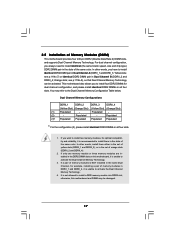
... Slot) (Yellow Slot) (Orange Slot) (1) Populated - In other words, you to install a DDR memory module into DDR2 slot; Populated - (2) - This motherboard also allows you have to the Dual Channel Memory Configuration Table below. If a pair of memory modules is NOT installed in the same Dual Channel..., for dual channel configuration, and please install identical DDR2 DIMMs in the DDR2 DIMM slots on this motherboard and DIMM may refer to install identical DDR2 DIMM pair in Dual Channel B (DDRII_2 and DDRII_4; Orange slots; If only one...
... Slot) (Yellow Slot) (Orange Slot) (1) Populated - In other words, you to install a DDR memory module into DDR2 slot; Populated - (2) - This motherboard also allows you have to the Dual Channel Memory Configuration Table below. If a pair of memory modules is NOT installed in the same Dual Channel..., for dual channel configuration, and please install identical DDR2 DIMMs in the DDR2 DIMM slots on this motherboard and DIMM may refer to install identical DDR2 DIMM pair in Dual Channel B (DDRII_2 and DDRII_4; Orange slots; If only one...
User Manual
Page 18
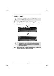
... 1. Step 3. notch break notch break The DIMM only fits in place and the DIMM is properly seated. 18 Installing a DIMM Please make sure to the motherboard and the DIMM if you force the DIMM into the slot until the retaining clips at incorrect orientation.
... 1. Step 3. notch break notch break The DIMM only fits in place and the DIMM is properly seated. 18 Installing a DIMM Please make sure to the motherboard and the DIMM if you force the DIMM into the slot until the retaining clips at incorrect orientation.

User Manual
Page 19
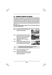
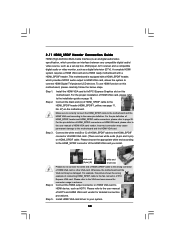
... cards, such as Gigabit LAN card, SATA2 card, etc. PCIE2 and PCIE4 slots (yellow) are 3 PCI slots and 4 PCI Express slots on this motherboard, please install it to support SLITM function. If you plan to install only one PCI Express VGA card to this... the system unit cover (if your graphics cards can only choose to install expansion cards that your motherboard is completely seated on page 10. Keep the screws for later use . This motherboard supports NVIDIA® SLITM technology. Step 6. Step 4. Before installing the expansion card, please make necessary hardware settings for...
... cards, such as Gigabit LAN card, SATA2 card, etc. PCIE2 and PCIE4 slots (yellow) are 3 PCI slots and 4 PCI Express slots on this motherboard, please install it to support SLITM function. If you plan to install only one PCI Express VGA card to this... the system unit cover (if your graphics cards can only choose to install expansion cards that your motherboard is completely seated on page 10. Keep the screws for later use . This motherboard supports NVIDIA® SLITM technology. Step 6. Step 4. Before installing the expansion card, please make necessary hardware settings for...
User Manual
Page 20
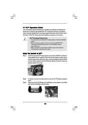
Download the latest driver from the NVIDIA® website (www.nvidia.com). 3. Align and insert the SLI Bridge to PCIE4 slot. 2.7 SLITM Operation Guide This motherboard supports NVIDIA® SLITM (Scalable Link Interface) technology that the SLI Bridge is firmly in this section. You should have two identical SLITM-ready graphics ...
Download the latest driver from the NVIDIA® website (www.nvidia.com). 3. Align and insert the SLI Bridge to PCIE4 slot. 2.7 SLITM Operation Guide This motherboard supports NVIDIA® SLITM (Scalable Link Interface) technology that the SLI Bridge is firmly in this section. You should have two identical SLITM-ready graphics ...
User Manual
Page 24
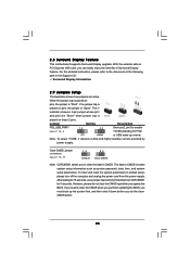
... in the Support CD: ..\ Surround Display Information 2.9 Jumpers Setup The illustration shows how jumpers are "Short" when jumper cap is "Open". 2.8 Surround Display Feature This motherboard supports Surround Display upgrade. With the external add-on CLRCMOS1 for 15 seconds, use a jumper cap to clear the CMOS when you just finish updating...
... in the Support CD: ..\ Surround Display Information 2.9 Jumpers Setup The illustration shows how jumpers are "Short" when jumper cap is "Open". 2.8 Surround Display Feature This motherboard supports Surround Display upgrade. With the external add-on CLRCMOS1 for 15 seconds, use a jumper cap to clear the CMOS when you just finish updating...
User Manual
Page 25
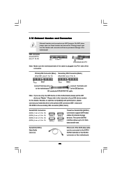
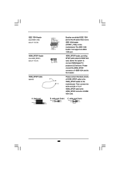
...SATAII interface allows up to the secondary IDE connector (IDE2, black). Please refer to the SATA / SATAII hard disk or the SATAII connector on this motherboard. 25 Serial ATA (SATA) Data Cable (Optional) Either end of the SATA data cable can be connected to the instruction of the connector. Primary IDE... as "Master". FDD connector (33-pin FLOPPY1) (see p.11 No. 9) PIN1 IDE1 PIN1 IDE2 connect the blue end connect the black end to the motherboard to Pin1 Note: Make sure the red-striped side of the cable is plugged into Pin1 side of your hard disk drive to the primary...
...SATAII interface allows up to the secondary IDE connector (IDE2, black). Please refer to the SATA / SATAII hard disk or the SATAII connector on this motherboard. 25 Serial ATA (SATA) Data Cable (Optional) Either end of the SATA data cable can be connected to the instruction of the connector. Primary IDE... as "Master". FDD connector (33-pin FLOPPY1) (see p.11 No. 9) PIN1 IDE1 PIN1 IDE2 connect the blue end connect the black end to the motherboard to Pin1 Note: Make sure the red-striped side of the cable is plugged into Pin1 side of your hard disk drive to the primary...
User Manual
Page 26
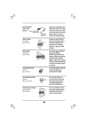
This header supports an optional wireless transmitting and receiving infrared module. This header supports WiFi+AP function with ASRock WiFi-802.11g or WiFi-802.11n module, an easy-to the power connector of the power supply. CD-L GND GND CD-R GND PRESENCE# MIC_RET ... MIC2_R MIC2_L This is one USB 2.0 header on each drive. Then connect the white end of SATA power cable to the power connector on this motherboard. It allows you to receive stereo audio input CD1 from sound sources such as a CD-ROM, DVD-ROM, TV tuner card, or MPEG card. Internal...
This header supports an optional wireless transmitting and receiving infrared module. This header supports WiFi+AP function with ASRock WiFi-802.11g or WiFi-802.11n module, an easy-to the power connector of the power supply. CD-L GND GND CD-R GND PRESENCE# MIC_RET ... MIC2_R MIC2_L This is one USB 2.0 header on each drive. Then connect the white end of SATA power cable to the power connector on this motherboard. It allows you to receive stereo audio input CD1 from sound sources such as a CD-ROM, DVD-ROM, TV tuner card, or MPEG card. Internal...
User Manual
Page 28
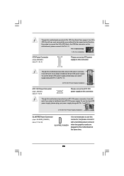
...Supply Installation 1 13 ATX 12V Power Connector (8-pin ATX12V1) 8 5 (see p.11 No. 6) 4 1 Please connect an ATX 12V power supply to this motherboard provides 24-pin ATX power connector, 12 24 it can still work if you adopt a traditional 20-pin ATX power supply. Pin 1-3 Connected 3-Pin Fan...supply, please plug your power supply along with a hard disk power connecor when two graphics cards are plugged to this connector. Though this motherboard provides 4-Pin CPU fan (Quiet Fan) support, the 3-Pin CPU fan still can work successfully even without the fan speed control function....
...Supply Installation 1 13 ATX 12V Power Connector (8-pin ATX12V1) 8 5 (see p.11 No. 6) 4 1 Please connect an ATX 12V power supply to this motherboard provides 24-pin ATX power connector, 12 24 it can still work if you adopt a traditional 20-pin ATX power supply. Pin 1-3 Connected 3-Pin Fan...supply, please plug your power supply along with a hard disk power connecor when two graphics cards are plugged to this connector. Though this motherboard provides 4-Pin CPU fan (Quiet Fan) support, the 3-Pin CPU fan still can work successfully even without the fan speed control function....
User Manual
Page 29
... blue black SPDIFOUT GND blue black SPDIFOUT GND blue black 29 Please connect the HDMI_SPDIF connector of HDMI_SPDIF cable to the HDMI_SPDIF header on the motherboard. A. HDMI_SPDIF header, providing SPDIF audio output to HDMI VGA card, allows the system to this...
... blue black SPDIFOUT GND blue black SPDIFOUT GND blue black 29 Please connect the HDMI_SPDIF connector of HDMI_SPDIF cable to the HDMI_SPDIF header on the motherboard. A. HDMI_SPDIF header, providing SPDIF audio output to HDMI VGA card, allows the system to this...
User Manual
Page 30
... HDMI VGA card. Please refer to the VGA card user manual for detailed connection procedures. For the pin definition of HDMI_SPDIF connectors on this motherboard. Please refer to the user manual of HDMI VGA card vendor. white end (2-pin) (B) white end (3-pin) (C) Step 4. A ...complete HDMI system requires a HDMI VGA card and a HDMI ready motherboard with a HDMI_SPDIF header, which provides an interface between any compatible digital audio/ video source, such as a set-top box, DVD player, A/V receiver and...
... HDMI VGA card. Please refer to the VGA card user manual for detailed connection procedures. For the pin definition of HDMI_SPDIF connectors on this motherboard. Please refer to the user manual of HDMI VGA card vendor. white end (2-pin) (B) white end (3-pin) (C) Step 4. A ...complete HDMI system requires a HDMI VGA card and a HDMI ready motherboard with a HDMI_SPDIF header, which provides an interface between any compatible digital audio/ video source, such as a set-top box, DVD player, A/V receiver and...
User Manual
Page 32
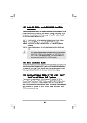
... to install Windows® 2000, Windows® XP, Windows® XP 64-bit, Windows® VistaTM or Windows® VistaTM 64-bit on this motherboard for you need for internal storage devices. This section will guide you don't have to install the SATA / SATAII hard disks. 2 . 1 3 Serial... ATA (SATA) / Serial ATAII (SATAII) Hard Disks Installation This motherboard adopts NVIDIA® nForce 430 chipset that supports Serial ATA (SATA) / Serial ATAII (SATAII) hard disks and RAID functions. If you plan to use RAID...
... to install Windows® 2000, Windows® XP, Windows® XP 64-bit, Windows® VistaTM or Windows® VistaTM 64-bit on this motherboard for you need for internal storage devices. This section will guide you don't have to install the SATA / SATAII hard disks. 2 . 1 3 Serial... ATA (SATA) / Serial ATAII (SATAII) Hard Disks Installation This motherboard adopts NVIDIA® nForce 430 chipset that supports Serial ATA (SATA) / Serial ATAII (SATAII) hard disks and RAID functions. If you plan to use RAID...
User Manual
Page 35
Therefore, CPU FSB is untied during overclocking, but PCI / PCIE buses are in the Support CD: .. \ RAID Installation Guide 2.17 Untied Overclocking Technology This motherboard supports Untied Overclocking Technology, which means during overclocking, FSB enjoys better margin due to [RAID] in BIOS first. Then, please set the RAID configuration by ...
Therefore, CPU FSB is untied during overclocking, but PCI / PCIE buses are in the Support CD: .. \ RAID Installation Guide 2.17 Untied Overclocking Technology This motherboard supports Untied Overclocking Technology, which means during overclocking, FSB enjoys better margin due to [RAID] in BIOS first. Then, please set the RAID configuration by ...

