
User Manual
Page 3
Security Menu 23 3. Advanced Menu 21 2. Boot Menu 25 5. Exit Menu 25 3 Power Menu 24 4. Contents 1 Introduction 4 1.1 Package Contents 4 1.2 Specifications 4 1.3 Motherboard Layout (PE Pro 6 1.4 Motherboard Layout (GE Pro 7 1.5 Motherboard Layout (G Pro A 8 1.6 ASRock I/OTM (PE Pro / GE Pro / G Pro A 9 2 Installation 10 2.1 Screw Holes 10 2.2 Pre-installation Precautions 10 2.3 CPU Installation 10 2.4 Installation of Heatsink and CPU fan 11 2.5 Installation of Memory Modules (DIMM 11...
Security Menu 23 3. Advanced Menu 21 2. Boot Menu 25 5. Exit Menu 25 3 Power Menu 24 4. Contents 1 Introduction 4 1.1 Package Contents 4 1.2 Specifications 4 1.3 Motherboard Layout (PE Pro 6 1.4 Motherboard Layout (GE Pro 7 1.5 Motherboard Layout (G Pro A 8 1.6 ASRock I/OTM (PE Pro / GE Pro / G Pro A 9 2 Installation 10 2.1 Screw Holes 10 2.2 Pre-installation Precautions 10 2.3 CPU Installation 10 2.4 Installation of Heatsink and CPU fan 11 2.5 Installation of Memory Modules (DIMM 11...

User Manual
Page 4
... this manual contain introduction of the motherboard and step-bystep installation guide for purchasing ASRock PE Pro / GE Pro / G Pro A motherboard, a reliable motherboard produced under ASRock's consistently stringent quality control. For advanced users' reference, the Appendix offers more advanced BIOS setup information. 1.1 Package Contents ASRock PE Pro, GE Pro, or G Pro A motherboard (ATX form factor: 12" x 9.6") ASRock PE Pro / GE Pro / G Pro A Quick Installation Guide ASRock Intel-SiS Series Support CD...
... this manual contain introduction of the motherboard and step-bystep installation guide for purchasing ASRock PE Pro / GE Pro / G Pro A motherboard, a reliable motherboard produced under ASRock's consistently stringent quality control. For advanced users' reference, the Appendix offers more advanced BIOS setup information. 1.1 Package Contents ASRock PE Pro, GE Pro, or G Pro A motherboard (ATX form factor: 12" x 9.6") ASRock PE Pro / GE Pro / G Pro A Quick Installation Guide ASRock Intel-SiS Series Support CD...

User Manual
Page 5
... supports 3.3v / 1.5v, 4X / 2X / 1X AGP card VGA Header (only on the motherboard functions properly before you resume the system. 2. Supports "Plug and Play"; Although PE Pro/GE Pro/ G Pro A offers stepless control, it is detected, the system will automatically shutdown. Supports jumperfree; Please check... (USB 2.0); 1 serial port: COM1; 1 parallel port: ECP/EPP support; While CPU overheat is not recommended to protect CPU life (ASRock U-COP); Chassis temperature sensing; Audio: 5.1 channels AC'97 Audio LAN: Speed: 802.3u (10/100 Ethernet), supports Wake-On-LAN ...
... supports 3.3v / 1.5v, 4X / 2X / 1X AGP card VGA Header (only on the motherboard functions properly before you resume the system. 2. Supports "Plug and Play"; Although PE Pro/GE Pro/ G Pro A offers stepless control, it is detected, the system will automatically shutdown. Supports jumperfree; Please check... (USB 2.0); 1 serial port: COM1; 1 parallel port: ECP/EPP support; While CPU overheat is not recommended to protect CPU life (ASRock U-COP); Chassis temperature sensing; Audio: 5.1 channels AC'97 Audio LAN: Speed: 802.3u (10/100 Ethernet), supports Wake-On-LAN ...

User Manual
Page 6
1.3 Motherboard Layout (PE Pro) 22 3 1 24.4cm (9.6 in) 24 5 6 PS/2 Mouse PS/2 Keyboard CPU_FAN1 1 PS2_USB_PWR1 COM1 PARALLEL PORT DDR DIMM1 (64/72 bit, 184-pin module) DDR DIMM2 (64/... BIOS 18 8 7 SiS 645 Chipset Accelerated Graphics Port 01 23 01 23 IDE2 IDE1 25 PCI 1 PCI 2 PCI 3 PCI 4 PCI 5 SiS South Bridge 9 CHA_FAN1 16 PE PRO FLOPPY1 CLRCMOS1 CMOS Battery 1 IR1 1 SPEAKER1 1 USB45 10 14 15 13 17 PCI 6 1 ATX power connector (ATXPWR1) 2 CPU socket 3 CPU fan connector (CPU_FAN1) 4 North Bridge...
1.3 Motherboard Layout (PE Pro) 22 3 1 24.4cm (9.6 in) 24 5 6 PS/2 Mouse PS/2 Keyboard CPU_FAN1 1 PS2_USB_PWR1 COM1 PARALLEL PORT DDR DIMM1 (64/72 bit, 184-pin module) DDR DIMM2 (64/... BIOS 18 8 7 SiS 645 Chipset Accelerated Graphics Port 01 23 01 23 IDE2 IDE1 25 PCI 1 PCI 2 PCI 3 PCI 4 PCI 5 SiS South Bridge 9 CHA_FAN1 16 PE PRO FLOPPY1 CLRCMOS1 CMOS Battery 1 IR1 1 SPEAKER1 1 USB45 10 14 15 13 17 PCI 6 1 ATX power connector (ATXPWR1) 2 CPU socket 3 CPU fan connector (CPU_FAN1) 4 North Bridge...

User Manual
Page 7
1.4 Motherboard Layout (GE Pro) 22 3 1 24.4cm (9.6 in) 24 5 6 PS/2 Mouse PS/2 Keyboard CPU_FAN1 1 PS2_USB_PWR1 COM1 PARALLEL PORT DDR DIMM1 (64/72 bit, 184-pin module) DDR DIMM2 (64/... I/O 11 2MB BIOS 18 Accelerated Graphics Port 01 23 01 23 IDE2 IDE1 25 PCI 1 PCI 2 PCI 3 PCI 4 PCI 5 SiS South Bridge 9 CHA_FAN1 16 GE PRO FLOPPY1 CLRCMOS1 CMOS Battery 1 IR1 1 SPEAKER1 1 USB45 10 14 15 13 17 PCI 6 ATA133 USB2.0 5.1CH PANEL 1 PLED PWRBTN 1 HDLED RST 12 1 ATX power connector...
1.4 Motherboard Layout (GE Pro) 22 3 1 24.4cm (9.6 in) 24 5 6 PS/2 Mouse PS/2 Keyboard CPU_FAN1 1 PS2_USB_PWR1 COM1 PARALLEL PORT DDR DIMM1 (64/72 bit, 184-pin module) DDR DIMM2 (64/... I/O 11 2MB BIOS 18 Accelerated Graphics Port 01 23 01 23 IDE2 IDE1 25 PCI 1 PCI 2 PCI 3 PCI 4 PCI 5 SiS South Bridge 9 CHA_FAN1 16 GE PRO FLOPPY1 CLRCMOS1 CMOS Battery 1 IR1 1 SPEAKER1 1 USB45 10 14 15 13 17 PCI 6 ATA133 USB2.0 5.1CH PANEL 1 PLED PWRBTN 1 HDLED RST 12 1 ATX power connector...
User Manual
Page 8
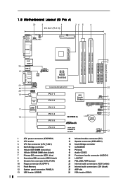
1.5 Motherboard Layout (G Pro A) 22 3 1 24.4cm (9.6 in) 24 5 6 PS/2 Mouse PS/2 Keyboard CPU_FAN1 1 PS2_USB_PWR1 COM1 PARALLEL PORT DDR DIMM1 (64/72 bit, 184-pin module) DDR DIMM2 (64/... Super I/O 11 2MB BIOS 18 Accelerated Graphics Port 01 23 01 23 IDE2 IDE1 25 PCI 1 PCI 2 PCI 3 PCI 4 PCI 5 SiS South Bridge 9 CHA_FAN1 16 G PRO A FLOPPY1 CLRCMOS1 CMOS Battery 1 IR1 1 SPEAKER1 1 USB45 10 14 15 13 17 PCI 6 1 ATX power connector (ATXPWR1) 2 CPU socket 3 CPU fan connector (CPU_FAN1) 4 North Bridge...
1.5 Motherboard Layout (G Pro A) 22 3 1 24.4cm (9.6 in) 24 5 6 PS/2 Mouse PS/2 Keyboard CPU_FAN1 1 PS2_USB_PWR1 COM1 PARALLEL PORT DDR DIMM1 (64/72 bit, 184-pin module) DDR DIMM2 (64/... Super I/O 11 2MB BIOS 18 Accelerated Graphics Port 01 23 01 23 IDE2 IDE1 25 PCI 1 PCI 2 PCI 3 PCI 4 PCI 5 SiS South Bridge 9 CHA_FAN1 16 G PRO A FLOPPY1 CLRCMOS1 CMOS Battery 1 IR1 1 SPEAKER1 1 USB45 10 14 15 13 17 PCI 6 1 ATX power connector (ATXPWR1) 2 CPU socket 3 CPU fan connector (CPU_FAN1) 4 North Bridge...

User Manual
Page 10
... strap or touch a safety grounded object before you and damages to the motherboard, peripherals, and/or components. 2.3 CPU Installation Step 1. Before you install motherboard components or change any component. 2. Chapter 2 Installation PE Pro / GE Pro / G Pro A is detached from the wall socket before touching any motherboard settings. 1. Position the CPU directly above the socket such that the...
... strap or touch a safety grounded object before you and damages to the motherboard, peripherals, and/or components. 2.3 CPU Installation Step 1. Before you install motherboard components or change any component. 2. Chapter 2 Installation PE Pro / GE Pro / G Pro A is detached from the wall socket before touching any motherboard settings. 1. Position the CPU directly above the socket such that the...

User Manual
Page 12
...pins. 12 Step 2. Step 5. The illustration shows a 3-pin jumper whose pin1 and pin2 are 6 PCI slots and 1 AGP slot on both PE Pro and GE Pro motherboards. Step 3. Replace the system cover. 2.7 Jumpers Setup The illustration shows how jumpers are used to the chassis with the slot and press firmly ... (PCI and AGP Slots) There are "SHORT" when jumper cap is placed on pins, the jumper is placed on the slot. Step 6. The ASRock AGP slot has a special locking mechanism which can securely fasten the graphics card inserted. Step 4. Fasten the card to install a graphics card. PCI ...
...pins. 12 Step 2. Step 5. The illustration shows a 3-pin jumper whose pin1 and pin2 are 6 PCI slots and 1 AGP slot on both PE Pro and GE Pro motherboards. Step 3. Replace the system cover. 2.7 Jumpers Setup The illustration shows how jumpers are used to the chassis with the slot and press firmly ... (PCI and AGP Slots) There are "SHORT" when jumper cap is placed on pins, the jumper is placed on the slot. Step 6. The ASRock AGP slot has a special locking mechanism which can securely fasten the graphics card inserted. Step 4. Fasten the card to install a graphics card. PCI ...

User Manual
Page 13
... the power cord, then short the solder points to the secondary IDE connector (IDE2, black). 13 CLRCMOS1 (see p.6/p.7/p.8 item 8) PIN1 IDE1 Blue Connect to the motherboard PIN1 IDE2 Black Connect to the IDE devices 80-Pin ATA 100/133 cable Note: To optimize compatibility and performance, please connect your hard disk...
... the power cord, then short the solder points to the secondary IDE connector (IDE2, black). 13 CLRCMOS1 (see p.6/p.7/p.8 item 8) PIN1 IDE1 Blue Connect to the motherboard PIN1 IDE2 Black Connect to the IDE devices 80-Pin ATA 100/133 cable Note: To optimize compatibility and performance, please connect your hard disk...

User Manual
Page 16
... advanced features SECURITY Sets up the computer, there is used to be user-friendly. You can also restart by pressing the reset button on the motherboard stores the BIOS Setup Utility. The following table lists the keys in the legend bar with their corresponding functions. 16
... advanced features SECURITY Sets up the computer, there is used to be user-friendly. You can also restart by pressing the reset button on the motherboard stores the BIOS Setup Utility. The following table lists the keys in the legend bar with their corresponding functions. 16

User Manual
Page 20
... you a multimedia PC-DIY live demo, which shows you need to contact ASRock or want to activate the devices. 4.2.3 Utilities Menu The Utilities Menu shows the applications software that enhance the motherboard features. 4.2.1 Running The Support CD To begin using the support CD, insert the CD into your CD-ROM drive. You...
... you a multimedia PC-DIY live demo, which shows you need to contact ASRock or want to activate the devices. 4.2.3 Utilities Menu The Utilities Menu shows the applications software that enhance the motherboard features. 4.2.1 Running The Support CD To begin using the support CD, insert the CD into your CD-ROM drive. You...

User Manual
Page 21
...", "Power", "Boot", and "Exit". 1. USB Controller: Use this to select the value as operating frequency. SDRAM Frequency: [Auto]: The motherboard detects the memory module(s) inserted and automatically assigns appropriate frequency. [Other values]: This allows user to enable or disable the use of USB controller.... better system stability. OnBoard VGA Share Memory: This allows you leave this is not inserted. CPU Host Frequency: [Auto]: The motherboard detects the jumper setup and sets the CPU host frequency automatically. [Manual]: This allows user to set CPU host frequency manually. ...
...", "Power", "Boot", and "Exit". 1. USB Controller: Use this to select the value as operating frequency. SDRAM Frequency: [Auto]: The motherboard detects the memory module(s) inserted and automatically assigns appropriate frequency. [Other values]: This allows user to enable or disable the use of USB controller.... better system stability. OnBoard VGA Share Memory: This allows you leave this is not inserted. CPU Host Frequency: [Auto]: The motherboard detects the jumper setup and sets the CPU host frequency automatically. [Manual]: This allows user to set CPU host frequency manually. ...

User Manual
Page 23
... already have a password, you must enter your current password first in order to 6 alphanumeric characters combination. Password Check: Select the check point for CPU temperature, Motherboard temperature, CPU fan speed, and critical voltage. 2.
... already have a password, you must enter your current password first in order to 6 alphanumeric characters combination. Password Check: Select the check point for CPU temperature, Motherboard temperature, CPU fan speed, and critical voltage. 2.

