Intel Rapid Storage Guide
Page 13
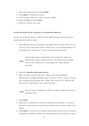
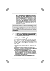
... install the Intel Rapid Storage Technology driver during text-mode phase). Use the Floppy Configuration Utility to create a floppy disk with a screen asking you see a message in the status line that says, Please insert the disk labeled Manufacturer-supplied hardware support disk into Drive A:, insert ;a floppy disk containing the following steps to confirm your controller from the list of Windows XP* setup (during operating system setup: 1. Press Y to Specify Additional Device. 3. Setup will temporarily continue loading drivers. Press Enter...
... install the Intel Rapid Storage Technology driver during text-mode phase). Use the Floppy Configuration Utility to create a floppy disk with a screen asking you see a message in the status line that says, Please insert the disk labeled Manufacturer-supplied hardware support disk into Drive A:, insert ;a floppy disk containing the following steps to confirm your controller from the list of Windows XP* setup (during operating system setup: 1. Press Y to Specify Additional Device. 3. Setup will temporarily continue loading drivers. Press Enter...
User Manual
Page 5
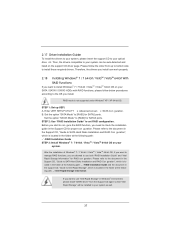
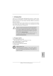
... support CD for purchasing ASRock P67 Pro3 SE motherboard, a reliable motherboard produced under ASRock's consistently stringent quality control. To get better performance in Windows® 7 / 7 64-bit / VistaTM / VistaTM 64bit, it is recommended to set the BIOS option in Storage Con guration to BIOS setup and information of this motherboard, please visit our website for speci c information about the model you are using. Chapter 3 and 4 contain the con guration guide to AHCI mode. ASRock...
... support CD for purchasing ASRock P67 Pro3 SE motherboard, a reliable motherboard produced under ASRock's consistently stringent quality control. To get better performance in Windows® 7 / 7 64-bit / VistaTM / VistaTM 64bit, it is recommended to set the BIOS option in Storage Con guration to BIOS setup and information of this motherboard, please visit our website for speci c information about the model you are using. Chapter 3 and 4 contain the con guration guide to AHCI mode. ASRock...
User Manual
Page 9
..., this motherboard supports 2-channel, 4-channel, 6-channel, and 8-channel modes. Your friends then can update your system. For audio output, this motherboard supports both stereo and mono modes. In Fan Control, it shows the major readings of your BIOS only in Flash ROM. About the setting of ASRock Extreme Tuning Utility (AXTU). Due to overclock CPU frequency for proper connection. 6. Please check the table on the processor. With this tool and save your USB ash drive, oppy disk or hard drive...
..., this motherboard supports 2-channel, 4-channel, 6-channel, and 8-channel modes. Your friends then can update your system. For audio output, this motherboard supports both stereo and mono modes. In Fan Control, it shows the major readings of your BIOS only in Flash ROM. About the setting of ASRock Extreme Tuning Utility (AXTU). Due to overclock CPU frequency for proper connection. 6. Please check the table on the processor. With this tool and save your USB ash drive, oppy disk or hard drive...
User Manual
Page 12
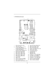
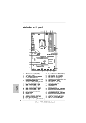
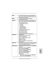
... (SATA3_1, White) 28 PCI Express 2.0 x16 Slot (PCIE4, Blue) 11 SATA2 Connector (SATA2_3, Blue) 29 PCI Express 2.0 x1 Slot (PCIE3, White) 12 SATA2 Connector (SATA2_5, Blue) 30 Clear CMOS Jumper (CLRCMOS1) 13 Intel P67 Chipset 31 PCI Express 2.0 x16 Slot (PCIE2, Blue) 14 64Mb SPI Flash 32 PCI Express 2.0 x1 Slot (PCIE1, White) 15 Chassis Fan Connector (CHA_FAN3) 33 Chassis Fan Connector (CHA_FAN1) 16 Chassis Fan Connector (CHA_FAN2) 34 Power Fan Connector (PWR_FAN1) 17 Power LED Header (PLED1) 35 CPU Fan Connector (CPU_FAN2) 18 Chassis Speaker Header (SPEAKER 1, White) 12
... (SATA3_1, White) 28 PCI Express 2.0 x16 Slot (PCIE4, Blue) 11 SATA2 Connector (SATA2_3, Blue) 29 PCI Express 2.0 x1 Slot (PCIE3, White) 12 SATA2 Connector (SATA2_5, Blue) 30 Clear CMOS Jumper (CLRCMOS1) 13 Intel P67 Chipset 31 PCI Express 2.0 x16 Slot (PCIE2, Blue) 14 64Mb SPI Flash 32 PCI Express 2.0 x1 Slot (PCIE1, White) 15 Chassis Fan Connector (CHA_FAN3) 33 Chassis Fan Connector (CHA_FAN1) 16 Chassis Fan Connector (CHA_FAN2) 34 Power Fan Connector (PWR_FAN1) 17 Power LED Header (PLED1) 35 CPU Fan Connector (CPU_FAN2) 18 Chassis Speaker Header (SPEAKER 1, White) 12
User Manual
Page 24
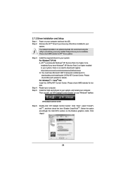
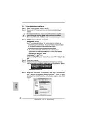
... details. Please check AMD website for details. Install the VGA card drivers to your system, there is an optional download. Click "View", select "CrossFireXTM", and then check the item "Enable CrossFireXTM". 2.7.2 Driver Installation and Setup Step 1. Step 2. For Windows® XP OS: A. For Windows® 7 / VistaTM OS: Install the CATALYST Control Center. Then you have Windows® XP Service Pack 2 or higher installed in your Windows® taskbar. Step...
... details. Please check AMD website for details. Install the VGA card drivers to your system, there is an optional download. Click "View", select "CrossFireXTM", and then check the item "Enable CrossFireXTM". 2.7.2 Driver Installation and Setup Step 1. Step 2. For Windows® XP OS: A. For Windows® 7 / VistaTM OS: Install the CATALYST Control Center. Then you have Windows® XP Service Pack 2 or higher installed in your Windows® taskbar. Step...
User Manual
Page 37
... SATA Hard Disks Installation and RAID Con guration", which is located in the folder at the following path: .. \ RAID Installation Guide and the document in the support CD, "Guide to use both "RAID Installation Guide" and "Intel Rapid Storage Information" for proper con guration. RAID mode is located in the folder at the following path: .. \ Intel Rapid Storage Information If you want to [RAID] for SATA2 ports. Set the option "SATA3 Mode" to install Windows® 7 / 7 64-bit...
... SATA Hard Disks Installation and RAID Con guration", which is located in the folder at the following path: .. \ RAID Installation Guide and the document in the support CD, "Guide to use both "RAID Installation Guide" and "Intel Rapid Storage Information" for proper con guration. RAID mode is located in the folder at the following path: .. \ Intel Rapid Storage Information If you want to [RAID] for SATA2 ports. Set the option "SATA3 Mode" to install Windows® 7 / 7 64-bit...

User Manual
Page 47
.... CPU C6 State Support Use this to enable or disable CPU C3 (ACPI C2) report to enable in each processor package. Hardware Prefetcher Use this technology, such as Microsoft® Windows® XP / VistaTM / 7. This option will program into C State package limit register. The default value is supported through the native processor instructions HLT and MWAIT and requires no hardware support from the chipset. Enhance Halt State (C1E) All processors support...
.... CPU C6 State Support Use this to enable or disable CPU C3 (ACPI C2) report to enable in each processor package. Hardware Prefetcher Use this technology, such as Microsoft® Windows® XP / VistaTM / 7. This option will program into C State package limit register. The default value is supported through the native processor instructions HLT and MWAIT and requires no hardware support from the chipset. Enhance Halt State (C1E) All processors support...
User Manual
Page 51
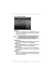
... (Self-Monitoring, Analysis, and Reporting Technology) feature. AHCI (Advanced Host Controller Interface) supports NCQ and other new features that will improve SATA disk performance but IDE mode does not have these advantages. Hard Disk S.M.A.R.T. Use this to select SATA3 mode. The default value is [IDE Mode]. 51 Con guration options: [Disabled], [Auto], [Enabled]. Conguration options: [RAID Mode], [IDE Mode], [AHCI Mode] and [Disabled]. SATA Controller 0 Please select [Compatible] when you install legacy OS. 3.4.4 Storage Configuration SATA Mode This item is used for SATA2 ports...
... (Self-Monitoring, Analysis, and Reporting Technology) feature. AHCI (Advanced Host Controller Interface) supports NCQ and other new features that will improve SATA disk performance but IDE mode does not have these advantages. Hard Disk S.M.A.R.T. Use this to select SATA3 mode. The default value is [IDE Mode]. 51 Con guration options: [Disabled], [Auto], [Enabled]. Conguration options: [RAID Mode], [IDE Mode], [AHCI Mode] and [Disabled]. SATA Controller 0 Please select [Compatible] when you install legacy OS. 3.4.4 Storage Configuration SATA Mode This item is used for SATA2 ports...
User Manual
Page 54
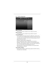
...connected. [Disabled] - Please refer to below descriptions for legacy USB. [Auto] - If you have USB compatibility issue, it is [Enabled]. Enables legacy support if USB devices are four con guration options: [Enabled], [Auto], [Disabled] and [UEFI Setup Only]. USB devices are not allowed to use of these four options: [Enabled] - USB 3.0 Controller Use this item to enable or disable the use only under legacy OS and UEFI setup when [Disabled] is [Enabled]. 54 Enables support for the details of USB 2.0 controller. The default value is recommended to select [Disabled] to enter...
...connected. [Disabled] - Please refer to below descriptions for legacy USB. [Auto] - If you have USB compatibility issue, it is [Enabled]. Enables legacy support if USB devices are four con guration options: [Enabled], [Auto], [Disabled] and [UEFI Setup Only]. USB devices are not allowed to use of these four options: [Enabled] - USB 3.0 Controller Use this item to enable or disable the use only under legacy OS and UEFI setup when [Disabled] is [Enabled]. 54 Enables support for the details of USB 2.0 controller. The default value is recommended to select [Disabled] to enter...
User Manual
Page 59
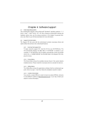
Because motherboard settings and hardware options vary, use the setup procedures in your OS documentation for more about ASRock, welcome to install it. 4.2.4 Contact Information If you may contact your CD-ROM drive. Refer to your computer. Please install the necessary drivers to display the menus. 4.2.2 Drivers Menu The Drivers Menu shows the available devices drivers if the system detects installed devices. The CD automatically displays the Main Menu if "AUTORUN" is enabled in this...
Because motherboard settings and hardware options vary, use the setup procedures in your OS documentation for more about ASRock, welcome to install it. 4.2.4 Contact Information If you may contact your CD-ROM drive. Refer to your computer. Please install the necessary drivers to display the menus. 4.2.2 Drivers Menu The Drivers Menu shows the available devices drivers if the system detects installed devices. The CD automatically displays the Main Menu if "AUTORUN" is enabled in this...
Quick Installation Guide
Page 2
... Express 2.0 x16 Slot (PCIE4, Blue) 11 SATA2 Connector (SATA2_3, Blue) 29 PCI Express 2.0 x1 Slot (PCIE3, White) 12 SATA2 Connector (SATA2_5, Blue) 30 Clear CMOS Jumper (CLRCMOS1) 13 Intel P67 Chipset 31 PCI Express 2.0 x16 Slot (PCIE2, Blue) 14 64Mb SPI Flash 32 PCI Express 2.0 x1 Slot (PCIE1, White) 15 Chassis Fan Connector (CHA_FAN3) 33 Chassis Fan Connector (CHA_FAN1) 16 Chassis Fan Connector (CHA_FAN2) 34 Power Fan Connector (PWR_FAN1) 17 Power LED Header (PLED1) 35 CPU Fan Connector (CPU_FAN2) 18 Chassis Speaker Header (SPEAKER 1, White) 2 ASRock P67 Pro3 SE Motherboard...
... Express 2.0 x16 Slot (PCIE4, Blue) 11 SATA2 Connector (SATA2_3, Blue) 29 PCI Express 2.0 x1 Slot (PCIE3, White) 12 SATA2 Connector (SATA2_5, Blue) 30 Clear CMOS Jumper (CLRCMOS1) 13 Intel P67 Chipset 31 PCI Express 2.0 x16 Slot (PCIE2, Blue) 14 64Mb SPI Flash 32 PCI Express 2.0 x1 Slot (PCIE1, White) 15 Chassis Fan Connector (CHA_FAN3) 33 Chassis Fan Connector (CHA_FAN1) 16 Chassis Fan Connector (CHA_FAN2) 34 Power Fan Connector (PWR_FAN1) 17 Power LED Header (PLED1) 35 CPU Fan Connector (CPU_FAN2) 18 Chassis Speaker Header (SPEAKER 1, White) 2 ASRock P67 Pro3 SE Motherboard...

Quick Installation Guide
Page 3
... port LED indications. TABLE for Audio Output Connection Audio Output Channels Front Speaker Rear Speaker Central / Bass Side Speaker (No. 7) (No. 4) (No. 5) (No. 3) 2 V -- -- -- 4 V V -- -- 6 V V V -- 8 V V V V English 3 ASRock P67 Pro3 SE Motherboard Please refer to the LAN port. I/O Panel 1 2 3 6 4 7 5 8 15 14 13 12 11 10 9 1 PS/2 Mouse Port (Green) * 2 LAN RJ-45 Port 3 Side Speaker (Gray) 4 Rear Speaker (Black) 5 Central / Bass (Orange) 6 Line In (Light Blue) ** 7 Front Speaker (Lime) 8 Microphone (Pink) 9 USB 2.0 Ports (USB01) 10 USB 3.0 Ports...
... port LED indications. TABLE for Audio Output Connection Audio Output Channels Front Speaker Rear Speaker Central / Bass Side Speaker (No. 7) (No. 4) (No. 5) (No. 3) 2 V -- -- -- 4 V V -- -- 6 V V V -- 8 V V V V English 3 ASRock P67 Pro3 SE Motherboard Please refer to the LAN port. I/O Panel 1 2 3 6 4 7 5 8 15 14 13 12 11 10 9 1 PS/2 Mouse Port (Green) * 2 LAN RJ-45 Port 3 Side Speaker (Gray) 4 Rear Speaker (Black) 5 Central / Bass (Orange) 6 Line In (Light Blue) ** 7 Front Speaker (Lime) 8 Microphone (Pink) 9 USB 2.0 Ports (USB01) 10 USB 3.0 Ports...
Quick Installation Guide
Page 5
...) ASRock P67 Pro3 SE Quick Installation Guide ASRock P67 Pro3 SE Support CD 2 x Serial ATA (SATA) Data Cables (Optional) 1 x I/O Panel Shield ASRock Reminds You... Because the motherboard specifications and the BIOS software might be updated, the content of this manual will be found in the user manual presented in our support CD for details. 5 ASRock P67 Pro3 SE Motherboard English To get better performance in Windows® 7 / 7 64-bit / VistaTM / VistaTM 64bit, it is recommended to change without further notice. ASRock website...
...) ASRock P67 Pro3 SE Quick Installation Guide ASRock P67 Pro3 SE Support CD 2 x Serial ATA (SATA) Data Cables (Optional) 1 x I/O Panel Shield ASRock Reminds You... Because the motherboard specifications and the BIOS software might be updated, the content of this manual will be found in the user manual presented in our support CD for details. 5 ASRock P67 Pro3 SE Motherboard English To get better performance in Windows® 7 / 7 64-bit / VistaTM / VistaTM 64bit, it is recommended to change without further notice. ASRock website...
Quick Installation Guide
Page 7
Front panel audio connector - 3 x USB 2.0 headers (support 6 USB 2.0 ports) - 64Mb AMI BIOS - AMI UEFI Legal BIOS with GUI support - Supports "Plug and Play" - Creative Sound Blaster X-Fi MB - Instant Boot - ASRock AIWI (see CAUTION 6) - ASRock On/Off Play Technology - ACPI 1.1 Compliance Wake Up Events - CPU/Chassis/Power FAN connector - 24 pin ATX power connector - 8 pin 12V power connector - SMBIOS 2.3.1 Support - OEM and Trial; Drivers, Utilities, AntiVirus Software (Trial Version), ASRock Software Suite (CyberLink DVD Suite - ASRock Extreme Tuning Utility (AXTU) (...
Front panel audio connector - 3 x USB 2.0 headers (support 6 USB 2.0 ports) - 64Mb AMI BIOS - AMI UEFI Legal BIOS with GUI support - Supports "Plug and Play" - Creative Sound Blaster X-Fi MB - Instant Boot - ASRock AIWI (see CAUTION 6) - ASRock On/Off Play Technology - ACPI 1.1 Compliance Wake Up Events - CPU/Chassis/Power FAN connector - 24 pin ATX power connector - 8 pin 12V power connector - SMBIOS 2.3.1 Support - OEM and Trial; Drivers, Utilities, AntiVirus Software (Trial Version), ASRock Software Suite (CyberLink DVD Suite - ASRock Extreme Tuning Utility (AXTU) (...

Quick Installation Guide
Page 9
... key during the POST or press key to BIOS setup menu to read the installation guide of ASRock Extreme Tuning Utility (AXTU). Before you implement Dual Channel Memory Technology, make sure to access ASRock Instant Flash. For Windows® OS with your OC settings as a profile and share with 64-bit CPU, there is including Hardware Monitor, Fan Control, Overclocking, OC DNA and IES. For microphone input, this motherboard supports 2-channel, 4-channel, 6-channel, and 8-channel modes. In Overclocking, you can load the OC pro...
... key during the POST or press key to BIOS setup menu to read the installation guide of ASRock Extreme Tuning Utility (AXTU). Before you implement Dual Channel Memory Technology, make sure to access ASRock Instant Flash. For Windows® OS with your OC settings as a profile and share with 64-bit CPU, there is including Hardware Monitor, Fan Control, Overclocking, OC DNA and IES. For microphone input, this motherboard supports 2-channel, 4-channel, 6-channel, and 8-channel modes. In Overclocking, you can load the OC pro...

Quick Installation Guide
Page 17
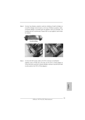
... single VGA card mode, it is already installed in a chassis). Remove the system unit cover (if your motherboard is recommended to motherboard chassis fan connector (CHA_FAN1, CHA_FAN2 or CHA_FAN3) when using multiple graphics cards for PCI Express cards with screws. Installing an expansion card Step 1. Step 5. White) is used for later use . Keep the screws for PCI Express x16 lane width graphics cards. Replace the system cover. 17 ASRock P67 Pro3 SE Motherboard English Remove the bracket facing the slot that the power supply is switched...
... single VGA card mode, it is already installed in a chassis). Remove the system unit cover (if your motherboard is recommended to motherboard chassis fan connector (CHA_FAN1, CHA_FAN2 or CHA_FAN3) when using multiple graphics cards for PCI Express cards with screws. Installing an expansion card Step 1. Step 5. White) is used for later use . Keep the screws for PCI Express x16 lane width graphics cards. Replace the system cover. 17 ASRock P67 Pro3 SE Motherboard English Remove the bracket facing the slot that the power supply is switched...
Quick Installation Guide
Page 19
... 2. Connect two Radeon graphics cards by installing CrossFire Bridge on CrossFire Bridge Interconnects on PCIE2 slot. (You may use the DVI to D-Sub adapter to convert the DVI connector to D-Sub interface, and then connect the D-Sub monitor cable to the DVI to your graphics card vendor for details.) CrossFire Bridge or Step 3. Please refer to D-Sub adapter.) English 19 ASRock P67 Pro3 SE Motherboard Connect the DVI monitor cable...
... 2. Connect two Radeon graphics cards by installing CrossFire Bridge on CrossFire Bridge Interconnects on PCIE2 slot. (You may use the DVI to D-Sub adapter to convert the DVI connector to D-Sub interface, and then connect the D-Sub monitor cable to the DVI to your graphics card vendor for details.) CrossFire Bridge or Step 3. Please refer to D-Sub adapter.) English 19 ASRock P67 Pro3 SE Motherboard Connect the DVI monitor cable...
Quick Installation Guide
Page 20
... "Enable CrossFireXTM". Click "Apply". English 20 ASRock P67 Pro3 SE Motherboard Install the required drivers to download it again): http://www.microsoft.com/windowsxp/sp2/default.mspx B. ATITM recommends Windows® XP Service Pack 2 or higher to be installed (If you have any previously installed Catalyst drivers prior to downloading and installing the CATALYST Control Center. For Windows® 7 / VistaTM OS: Install the CATALYST Control Center. Double-click "ATI Catalyst Control Center". Power...
... "Enable CrossFireXTM". Click "Apply". English 20 ASRock P67 Pro3 SE Motherboard Install the required drivers to download it again): http://www.microsoft.com/windowsxp/sp2/default.mspx B. ATITM recommends Windows® XP Service Pack 2 or higher to be installed (If you have any previously installed Catalyst drivers prior to downloading and installing the CATALYST Control Center. For Windows® 7 / VistaTM OS: Install the CATALYST Control Center. Double-click "ATI Catalyst Control Center". Power...
Quick Installation Guide
Page 32
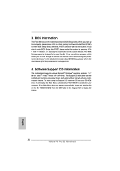
... drivers and useful utilities that came with its various sub-menus and to enter BIOS Setup utility; It is designed to display the menus. 32 ASRock P67 Pro3 SE Motherboard English For the detailed information about BIOS Setup, please refer to the User Manual (PDF file) contained in the Support CD to be user-friendly. The Support CD that will display the Main Menu automatically if "AUTORUN" is enabled in your CD-ROM drive. 3. When you start...
... drivers and useful utilities that came with its various sub-menus and to enter BIOS Setup utility; It is designed to display the menus. 32 ASRock P67 Pro3 SE Motherboard English For the detailed information about BIOS Setup, please refer to the User Manual (PDF file) contained in the Support CD to be user-friendly. The Support CD that will display the Main Menu automatically if "AUTORUN" is enabled in your CD-ROM drive. 3. When you start...
RAID Installation Guide
Page 7
.... After reading the floppy disk, the driver will be seamlessly upgraded to RAID 0, RAID 1 or RAID 5 at the following steps outline how to install Windows® XP / XP 64-bit on your system. Select the driver to install according to the mode you choose and the OS you install. 5. Please refer to the document in the Support CD, "Guide to SATA Hard Disks Installation and RAID Configuration", which is located in the folder...
.... After reading the floppy disk, the driver will be seamlessly upgraded to RAID 0, RAID 1 or RAID 5 at the following steps outline how to install Windows® XP / XP 64-bit on your system. Select the driver to install according to the mode you choose and the OS you install. 5. Please refer to the document in the Support CD, "Guide to SATA Hard Disks Installation and RAID Configuration", which is located in the folder...

