User Manual
Page 12
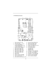
1.3 Motherboard Layout 1 2 3 19.1cm (7.5 in) PS2 Mouse PS2 CPU_FAN1 ATX12V1 4... 8 SATA2_4 SATA2_2 SATA3_0 9 PCI Express 2.0 SATA2_5 SATA2_3 SATA3_1 10 11 PCIE2 12 SATA3 6Gb/s 31 P67 Pro3 SE Super I/O CMOS Intel 30 Battery 1 P67 29 PCIE3 CLRCMOS1 13 28 27 AUDIO CODEC 1 HDMI_SPDIF1 HD_AUDIO1 1 IR1 1 PCIE4 ErP/EuP Ready RoHS ... 24 23 22 21 20 19 18 17 1 CPU Fan Connector (CPU_FAN1) 19 System Panel Header (PANEL1, White) 2 1155-Pin CPU Socket 20 USB 2.0 Header (USB12_13, Blue) 3 ATX 12V Power Connector (ATX12V1) 21 USB 2.0 Header (USB10_11, Blue) ...
1.3 Motherboard Layout 1 2 3 19.1cm (7.5 in) PS2 Mouse PS2 CPU_FAN1 ATX12V1 4... 8 SATA2_4 SATA2_2 SATA3_0 9 PCI Express 2.0 SATA2_5 SATA2_3 SATA3_1 10 11 PCIE2 12 SATA3 6Gb/s 31 P67 Pro3 SE Super I/O CMOS Intel 30 Battery 1 P67 29 PCIE3 CLRCMOS1 13 28 27 AUDIO CODEC 1 HDMI_SPDIF1 HD_AUDIO1 1 IR1 1 PCIE4 ErP/EuP Ready RoHS ... 24 23 22 21 20 19 18 17 1 CPU Fan Connector (CPU_FAN1) 19 System Panel Header (PANEL1, White) 2 1155-Pin CPU Socket 20 USB 2.0 Header (USB12_13, Blue) 3 ATX 12V Power Connector (ATX12V1) 21 USB 2.0 Header (USB10_11, Blue) ...
Quick Installation Guide
Page 2
... SATA2_4 SATA2_2 SATA3_0 9 PCI Express 2.0 SATA2_5 SATA2_3 SATA3_1 10 11 PCIE2 12 SATA3 6Gb/s 31 P67 Pro3 SE Super I/O CMOS Intel 30 Battery 1 P67 29 PCIE3 CLRCMOS1 13 28 27 AUDIO CODEC 1 HDMI_SPDIF1 HD_AUDIO1 1 IR1 1 PCIE4 ErP/EuP Ready ... 23 22 21 20 19 18 17 1 CPU Fan Connector (CPU_FAN1) 19 System Panel Header (PANEL1, White) 2 1155-Pin CPU Socket 20 USB 2.0 Header (USB12_13, Blue) 3 ATX 12V Power Connector (ATX12V1) 21 USB 2.0 Header (USB10_11, Blue)... (CPU_FAN2) 18 Chassis Speaker Header (SPEAKER 1, White) 2 ASRock P67 Pro3 SE Motherboard English
... SATA2_4 SATA2_2 SATA3_0 9 PCI Express 2.0 SATA2_5 SATA2_3 SATA3_1 10 11 PCIE2 12 SATA3 6Gb/s 31 P67 Pro3 SE Super I/O CMOS Intel 30 Battery 1 P67 29 PCIE3 CLRCMOS1 13 28 27 AUDIO CODEC 1 HDMI_SPDIF1 HD_AUDIO1 1 IR1 1 PCIE4 ErP/EuP Ready ... 23 22 21 20 19 18 17 1 CPU Fan Connector (CPU_FAN1) 19 System Panel Header (PANEL1, White) 2 1155-Pin CPU Socket 20 USB 2.0 Header (USB12_13, Blue) 3 ATX 12V Power Connector (ATX12V1) 21 USB 2.0 Header (USB10_11, Blue)... (CPU_FAN2) 18 Chassis Speaker Header (SPEAKER 1, White) 2 ASRock P67 Pro3 SE Motherboard English

Quick Installation Guide
Page 11
According to define the power consumption for more details. 11 ASRock P67 Pro3 SE Motherboard English To meet the standard of the completed system shall be used. 15. For EuP... provides the flexible option to Intel's suggestion, the EuP ready power supply must meet EuP standard, an EuP ready motherboard and an EuP ready power supply are required. EuP, stands for Energy Using Product, was a provision regulated by European Union ... be under 100 mA current consumption. According to adopt three different CPU cooler types, Socket LGA 775, LGA 1155 and LGA 1156. 14.
According to define the power consumption for more details. 11 ASRock P67 Pro3 SE Motherboard English To meet the standard of the completed system shall be used. 15. For EuP... provides the flexible option to Intel's suggestion, the EuP ready power supply must meet EuP standard, an EuP ready motherboard and an EuP ready power supply are required. EuP, stands for Energy Using Product, was a provision regulated by European Union ... be under 100 mA current consumption. According to adopt three different CPU cooler types, Socket LGA 775, LGA 1155 and LGA 1156. 14.
Quick Installation Guide
Page 12
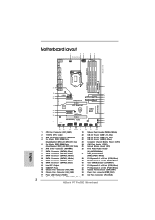
...socket before you uninstall any motherboard settings. 1. Whenever you handle components. 3. English 12 ASRock P67 Pro3 SE Motherboard Failure to the motherboard, peripherals, and/or components. 2. Otherwise, the CPU will be seriously damaged. Load Plate Contact Array Load Lever Socket Body 1155-Pin Socket Overview Before you install motherboard... cause severe damage to do so may damage the motherboard. 2.1 CPU Installation For the installation of the following precautions before you insert the 1155-Pin CPU into the socket, please check if the CPU surface is unclean or...
...socket before you uninstall any motherboard settings. 1. Whenever you handle components. 3. English 12 ASRock P67 Pro3 SE Motherboard Failure to the motherboard, peripherals, and/or components. 2. Otherwise, the CPU will be seriously damaged. Load Plate Contact Array Load Lever Socket Body 1155-Pin Socket Overview Before you install motherboard... cause severe damage to do so may damage the motherboard. 2.1 CPU Installation For the installation of the following precautions before you insert the 1155-Pin CPU into the socket, please check if the CPU surface is unclean or...
Quick Installation Guide
Page 13
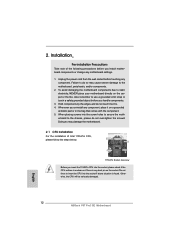
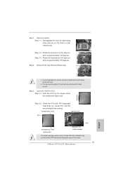
orientation key notch alignment key Pin1 Pin1 orientation key notch 1155-Pin CPU alignment key 1155-Pin Socket For proper inserting, please ensure to match the two orientation key notches of the socket. 13 ASRock P67 Pro3 SE Motherboard English Disengaging the lever by the edges where are marked with black lines. This cap must be placed if returning the...
orientation key notch alignment key Pin1 Pin1 orientation key notch 1155-Pin CPU alignment key 1155-Pin Socket For proper inserting, please ensure to match the two orientation key notches of the socket. 13 ASRock P67 Pro3 SE Motherboard English Disengaging the lever by the edges where are marked with black lines. This cap must be placed if returning the...
Quick Installation Guide
Page 14
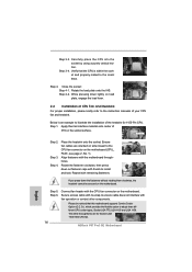
... slots pointing straight out Press Down (4 Places) If you press down on load plate, engage the load lever. 2.2 Installation of the heatsink for Socket LGA 1155/1156 CPU fan. 14 ASRock P67 Pro3 SE Motherboard English Align fasteners with fan operation or contact other components. Step 3-3. Rotate the load plate onto the IHS. Step 3-4. Step 4-2. The white...
... slots pointing straight out Press Down (4 Places) If you press down on load plate, engage the load lever. 2.2 Installation of the heatsink for Socket LGA 1155/1156 CPU fan. 14 ASRock P67 Pro3 SE Motherboard English Align fasteners with fan operation or contact other components. Step 3-3. Rotate the load plate onto the IHS. Step 3-4. Step 4-2. The white...
Quick Installation Guide
Page 191
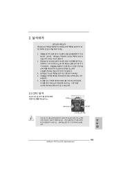
2 1 2 3 IC 4 5 2.1 CPU 설치 Intel 1155 핀 CPU 장착판 Load Plate Load Lever Contact Array Socket Body 1155 1155 핀 CPU CPU CPU CPU 한국어 191 ASRock P67 Pro3 SE Motherboard
2 1 2 3 IC 4 5 2.1 CPU 설치 Intel 1155 핀 CPU 장착판 Load Plate Load Lever Contact Array Socket Body 1155 1155 핀 CPU CPU CPU CPU 한국어 191 ASRock P67 Pro3 SE Motherboard
Quick Installation Guide
Page 215
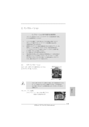
IC 4. 2.1 CPU Intel 1155-LAND CPU Load Plate Load Lever Contact Array Socket Body 1155 1155-LAND CPU CPU CPU CPU 1 1-1 日本語 215 ASRock P67 Pro3 SE Motherboard 1. 2. 3.
IC 4. 2.1 CPU Intel 1155-LAND CPU Load Plate Load Lever Contact Array Socket Body 1155 1155-LAND CPU CPU CPU CPU 1 1-1 日本語 215 ASRock P67 Pro3 SE Motherboard 1. 2. 3.

Quick Installation Guide
Page 217
4 4-1 HIS 4-2 4-3 2.2 CPU CPU 以下は、1155-LAND CPU 1 HIS Apply Thermal Interface Material 2 CPU_FAN1、2 No. 1 CPU 3 4 Fan cables on side closest to MB header Fastener slots pointing straight out Press Down (4 Places) 5 CPU 6 C.C.O Socket LGA 775、LGA 1155 と LGA 1156 の 3 CPU Socket LGA 1155/1156 CPU 日本語 217 ASRock P67 Pro3 SE Motherboard
4 4-1 HIS 4-2 4-3 2.2 CPU CPU 以下は、1155-LAND CPU 1 HIS Apply Thermal Interface Material 2 CPU_FAN1、2 No. 1 CPU 3 4 Fan cables on side closest to MB header Fastener slots pointing straight out Press Down (4 Places) 5 CPU 6 C.C.O Socket LGA 775、LGA 1155 と LGA 1156 の 3 CPU Socket LGA 1155/1156 CPU 日本語 217 ASRock P67 Pro3 SE Motherboard
Quick Installation Guide
Page 238
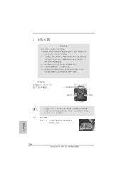
2 安全防范 1 2 3 4 5 2.1 CPU 安裝 要安裝 Intel 1155 針 CPU Load Plate Contact Array Load Lever Socket Body 1155 在您將 1155 針 CPU CPU CPU CPU 步驟 1. 1-1 簡體中文 238 ASRock P67 Pro3 SE Motherboard
2 安全防范 1 2 3 4 5 2.1 CPU 安裝 要安裝 Intel 1155 針 CPU Load Plate Contact Array Load Lever Socket Body 1155 在您將 1155 針 CPU CPU CPU CPU 步驟 1. 1-1 簡體中文 238 ASRock P67 Pro3 SE Motherboard

Quick Installation Guide
Page 261
2 安全防範 1 2 3 4 5 2.1 CPU 安裝 要安裝 Intel 1155 針 CPU Load Plate Contact Array Load Lever Socket Body ( 插槽 ) 1155 在您將 1155 針 CPU CPU CPU CPU 步驟 1. 1-1 繁體中文 261 ASRock P67 Pro3 SE Motherboard
2 安全防範 1 2 3 4 5 2.1 CPU 安裝 要安裝 Intel 1155 針 CPU Load Plate Contact Array Load Lever Socket Body ( 插槽 ) 1155 在您將 1155 針 CPU CPU CPU CPU 步驟 1. 1-1 繁體中文 261 ASRock P67 Pro3 SE Motherboard


