User Manual
Page 3
... 5 1.2 Specifications 6 1.3 Two CrossFireXTM Graphics Card Support List 10 1.4 Motherboard Layout 11 1.5 I/O Panel 12 2 Installation 14 2.1 Screw Holes 14 2.2 Pre-installation Precautions 14 2.3 CPU Installation 15 2.4 Installation of Heatsink and CPU fan 17 2.5 Installation of Memory Modules (DIMM 18 2.6 Expansion Slots (PCI and PCI Express Slots 20 2.7 CrossFireXTM and Quad CrossFireXTM Operation Guide...
... 5 1.2 Specifications 6 1.3 Two CrossFireXTM Graphics Card Support List 10 1.4 Motherboard Layout 11 1.5 I/O Panel 12 2 Installation 14 2.1 Screw Holes 14 2.2 Pre-installation Precautions 14 2.3 CPU Installation 15 2.4 Installation of Heatsink and CPU fan 17 2.5 Installation of Memory Modules (DIMM 18 2.6 Expansion Slots (PCI and PCI Express Slots 20 2.7 CrossFireXTM and Quad CrossFireXTM Operation Guide...

User Manual
Page 4
... Technology 43 3 BIOS SETUP UTILITY 44 3.1 Introduction 44 3.1.1 BIOS Menu Bar 44 3.1.2 Navigation Keys 45 3.2 Main Screen 45 3.3 OC Tweaker Screen 45 3.4 Advanced Screen 49 3.4.1 CPU Configuration 50 3.4.2 Chipset Configuration 52 3.4.3 ACPI Configuration 53 3.4.4 IDE Configuration 54 3.4.5 PCIPnP Configuration 56 3.4.6 Floppy Configuration 57 3.4.7 Super IO Configuration 57 3.4.8 USB Configuration 59 3.5 Hardware...
... Technology 43 3 BIOS SETUP UTILITY 44 3.1 Introduction 44 3.1.1 BIOS Menu Bar 44 3.1.2 Navigation Keys 45 3.2 Main Screen 45 3.3 OC Tweaker Screen 45 3.4 Advanced Screen 49 3.4.1 CPU Configuration 50 3.4.2 Chipset Configuration 52 3.4.3 ACPI Configuration 53 3.4.4 IDE Configuration 54 3.4.5 PCIPnP Configuration 56 3.4.6 Floppy Configuration 57 3.4.7 Super IO Configuration 57 3.4.8 USB Configuration 59 3.5 Hardware...

User Manual
Page 5
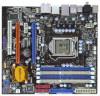
...x Serial ATA (SATA) HDD Power Cables (Optional) 1 x I/O Panel Shield 5 You may find the latest VGA cards and CPU support lists on ASRock website without notice. Chapter 1: Introduction Thank you are using. Chapter 3 and 4 contain the configuration guide to quality and endurance...BIOS software might be subject to the hardware installation. www.asrock.com/support/index.asp 1.1 Package Contents ASRock P55M Pro Motherboard (Micro ATX Form Factor: 9.6-in x 8.8-in, 24.4 cm x 22.4 cm) ASRock P55M Pro Quick Installation Guide ASRock P55M Pro Support CD 1 x 80-conductor Ultra ATA 66/100/133...
...x Serial ATA (SATA) HDD Power Cables (Optional) 1 x I/O Panel Shield 5 You may find the latest VGA cards and CPU support lists on ASRock website without notice. Chapter 1: Introduction Thank you are using. Chapter 3 and 4 contain the configuration guide to quality and endurance...BIOS software might be subject to the hardware installation. www.asrock.com/support/index.asp 1.1 Package Contents ASRock P55M Pro Motherboard (Micro ATX Form Factor: 9.6-in x 8.8-in, 24.4 cm x 22.4 cm) ASRock P55M Pro Quick Installation Guide ASRock P55M Pro Support CD 1 x 80-conductor Ultra ATA 66/100/133...

User Manual
Page 6
... Technology - HD Audio Jack: Side Speaker/Rear Speaker/Central/Bass/ Line in/Front Speaker/Microphone (see CAUTION 2) - Supports EM64T CPU - Supports Intel® Extreme Memory Profile (XMP) (see CAUTION 3) - 4 x DDR3 DIMM slots - Supports Wake-On-LAN I /O - 1.2 Specifications Platform... CPU Chipset Memory Expansion Slot Audio LAN Rear Panel I /O Panel - 1 x PS/2 Mouse Port - 1 x PS/2 Keyboard Port - 1 x Coaxial SPDIF Out Port - 1 x Optical SPDIF...
... Technology - HD Audio Jack: Side Speaker/Rear Speaker/Central/Bass/ Line in/Front Speaker/Microphone (see CAUTION 2) - Supports EM64T CPU - Supports Intel® Extreme Memory Profile (XMP) (see CAUTION 3) - 4 x DDR3 DIMM slots - Supports Wake-On-LAN I /O - 1.2 Specifications Platform... CPU Chipset Memory Expansion Slot Audio LAN Rear Panel I /O Panel - 1 x PS/2 Mouse Port - 1 x PS/2 Keyboard Port - 1 x Coaxial SPDIF Out Port - 1 x Optical SPDIF...

User Manual
Page 7
.../Power Fan Tachometer 7 Front panel audio connector - 3 x USB 2.0 headers (support 6 USB 2.0 ports) (see CAUTION 11) - CPU, VCCM, PCH,VTT Voltage Multi-adjustment - O. T. (Intelligent Overclocking Technology) - ASRock Instant Flash (see CAUTION 8) - 16Mb AMI BIOS - ASRock U-COP (see CAUTION 7) - 1 x ATA133 IDE connector (supports 2 x IDE devices) - 1 x Floppy connector - 1 x IR header - 1 x Print Port header - 1 x COM port header...
.../Power Fan Tachometer 7 Front panel audio connector - 3 x USB 2.0 headers (support 6 USB 2.0 ports) (see CAUTION 11) - CPU, VCCM, PCH,VTT Voltage Multi-adjustment - O. T. (Intelligent Overclocking Technology) - ASRock Instant Flash (see CAUTION 8) - 16Mb AMI BIOS - ASRock U-COP (see CAUTION 7) - 1 x ATA133 IDE connector (supports 2 x IDE devices) - 1 x Floppy connector - 1 x IR header - 1 x Print Port header - 1 x COM port header...
User Manual
Page 8
... adjusting the setting in the BIOS, applying Untied Overclocking Technology, or using the thirdparty overclocking tools. For those CPU that there is a certain risk involved with 64-bit CPU, there is a user-friendly ASRock overclocking tool which allows you implement Dual Channel Memory Technology, make sure to DDR3 1333, the XMP DDR3 1600...
... adjusting the setting in the BIOS, applying Untied Overclocking Technology, or using the thirdparty overclocking tools. For those CPU that there is a certain risk involved with 64-bit CPU, there is a user-friendly ASRock overclocking tool which allows you implement Dual Channel Memory Technology, make sure to DDR3 1333, the XMP DDR3 1600...
User Manual
Page 9
...of Intelligent Energy Saver. This convenient BIOS update tool allows you resume the system, please check if the CPU fan on the same motherboard. 13. Before you to access ASRock Instant Flash. For EuP ready power supply selection, we recommend you can load the OC profile to ... profile and share with others. To improve heat dissipation, remember to adopt two different CPU cooler types, Socket LGA 775 and LGA 1156. EuP, stands for Energy Using Product, was a provision regulated by ASRock, provides a convenient way for the completed system. According to record the OC settings ...
...of Intelligent Energy Saver. This convenient BIOS update tool allows you resume the system, please check if the CPU fan on the same motherboard. 13. Before you to access ASRock Instant Flash. For EuP ready power supply selection, we recommend you can load the OC profile to ... profile and share with others. To improve heat dissipation, remember to adopt two different CPU cooler types, Socket LGA 775 and LGA 1156. EuP, stands for Energy Using Product, was a provision regulated by ASRock, provides a convenient way for the completed system. According to record the OC settings ...
User Manual
Page 15
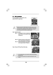
... PnP Cap (Pick and Place Cap). 1. This cap must be seriously damaged. Disengaging the lever by depressing down and out on the socket. Otherwise, the CPU will be placed if returning the motherboard for after service. 15 Step 1-3. Step 1. Rotate the load plate to handle and avoid kicking off the PnP... Lever Contact Array Socket Body 1156-Pin Socket Overview Before you insert the 1156-Pin CPU into the socket if above situation is found. Do not force to insert the CPU into the socket, please check if the CPU surface is unclean or if there is recommended to use the cap tab to...
... PnP Cap (Pick and Place Cap). 1. This cap must be seriously damaged. Disengaging the lever by depressing down and out on the socket. Otherwise, the CPU will be placed if returning the motherboard for after service. 15 Step 1-3. Step 1. Rotate the load plate to handle and avoid kicking off the PnP... Lever Contact Array Socket Body 1156-Pin Socket Overview Before you insert the 1156-Pin CPU into the socket if above situation is found. Do not force to insert the CPU into the socket, please check if the CPU surface is unclean or if there is recommended to use the cap tab to...

User Manual
Page 16
...line Step 3-2. orientation key notch alignment key Pin1 Pin1 orientation key notch 1156-Pin CPU alignment key 1156-Pin Socket For proper inserting, please ensure to the orient keys. Carefully place the CPU into the socket by the edge where is within the socket and properly mated to...) up. Close the socket: Step 4-1. Insert the 1156-Pin CPU: Step 3-1. Locate Pin1 and the two orientation key notches. Step 3-4. Step 4. Orient the CPU with black line. Rotate the load plate onto the IHS. Step 4-3. Hold the CPU by using a purely vertical motion. Step 3. While pressing down ...
...line Step 3-2. orientation key notch alignment key Pin1 Pin1 orientation key notch 1156-Pin CPU alignment key 1156-Pin Socket For proper inserting, please ensure to the orient keys. Carefully place the CPU into the socket by the edge where is within the socket and properly mated to...) up. Close the socket: Step 4-1. Insert the 1156-Pin CPU: Step 3-1. Locate Pin1 and the two orientation key notches. Step 3-4. Step 4. Orient the CPU with black line. Rotate the load plate onto the IHS. Step 4-3. Hold the CPU by using a purely vertical motion. Step 3. While pressing down ...

User Manual
Page 17
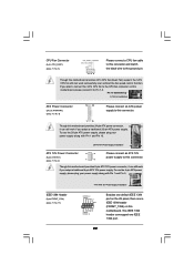
...onto the socket. Ensure fan cables are securely fastened and in good contact with 1156-Pin socket that supports Intel 1156-Pin CPU. Ensure that this motherboard supports Combo Cooler Option (C.C.O.), which provides the flexible option to ensure cable does not interfere with the...Apply Thermal Interface Material Step 2. Align fasteners with fan operation or contact other . Step 6. Apply thermal interface material onto center of CPU Fan and Heatsink This motherboard is an example to improve heat dissipation. 2.4 Installation of IHS on the socket surface. Step 3. Step...
...onto the socket. Ensure fan cables are securely fastened and in good contact with 1156-Pin socket that supports Intel 1156-Pin CPU. Ensure that this motherboard supports Combo Cooler Option (C.C.O.), which provides the flexible option to ensure cable does not interfere with the...Apply Thermal Interface Material Step 2. Align fasteners with fan operation or contact other . Step 6. Apply thermal interface material onto center of CPU Fan and Heatsink This motherboard is an example to improve heat dissipation. 2.4 Installation of IHS on the socket surface. Step 3. Step...
User Manual
Page 29
...this connector and match the black wire to Pin 1-3. This IEEE 1394 header can still work if you plan to connect the 3-Pin CPU fan to the CPU fan connector on the I/O panel, there is one IEEE 1394 port. 29 Pin 1-3 Connected 3-Pin Fan Installation ATX Power Connector (...24-pin ATXPWR1) (see p.11 No. 3) 1 2 3 4 Please connect a CPU fan cable to this motherboard, please connect it can work if you adopt a traditional 4-pin ATX 12V power supply. If you adopt a traditional 20-pin...
...this connector and match the black wire to Pin 1-3. This IEEE 1394 header can still work if you plan to connect the 3-Pin CPU fan to the CPU fan connector on the I/O panel, there is one IEEE 1394 port. 29 Pin 1-3 Connected 3-Pin Fan Installation ATX Power Connector (...24-pin ATXPWR1) (see p.11 No. 3) 1 2 3 4 Please connect a CPU fan cable to this motherboard, please connect it can work if you adopt a traditional 4-pin ATX 12V power supply. If you adopt a traditional 20-pin...
User Manual
Page 43
... "Overclock Mode" option of BIOS setup to set the selection from [Auto] to fixed PCI / PCIE buses. Before you apply Untied Overclocking Technology. 43 Therefore, CPU FSB is untied during overclocking, FSB enjoys better margin due to [Manual].
... "Overclock Mode" option of BIOS setup to set the selection from [Auto] to fixed PCI / PCIE buses. Before you apply Untied Overclocking Technology. 43 Therefore, CPU FSB is untied during overclocking, FSB enjoys better margin due to [Manual].

User Manual
Page 45
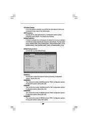
... OC Tweaker Advanced H/W Monitor Boot Security Exit System Overview System Time System Date [14:00:09] [Tue 07/14/2009] BIOS Version : P55M Pro P1.00 Processor Type : Intel (R) Core (TM) CPU 870 @ 2.93GHz (64bit) Processor Speed : 2933MHz Microcode Update : 106E5/3 Cache Size : 8192KB Total Memory DDR3_A2 DDR3_A1 DDR3_B2 DDR3_B1 : 2048MB Single-Channel...
... OC Tweaker Advanced H/W Monitor Boot Security Exit System Overview System Time System Date [14:00:09] [Tue 07/14/2009] BIOS Version : P55M Pro P1.00 Processor Type : Intel (R) Core (TM) CPU 870 @ 2.93GHz (64bit) Processor Speed : 2933MHz Microcode Update : 106E5/3 Cache Size : 8192KB Total Memory DDR3_A2 DDR3_A1 DDR3_B2 DDR3_B1 : 2048MB Single-Channel...
User Manual
Page 46
...your own risk and expense. It should be done at your memory and motherboard. CPU Ratio Setting QPI Frequency DRAM Frequency 21 [21] 4.800GT [Auto] DDR3_1333 [Auto] DRAM Timing Control ASRock VDrop Control CPU Voltage DRAM Voltage [With VDrop] [Auto] [Auto] Select Screen Select Item Enter... Go to your CPU and motherboard. Load CPU EZ OC Setting You can use this option to load memory EZ overclocking ...
...your own risk and expense. It should be done at your memory and motherboard. CPU Ratio Setting QPI Frequency DRAM Frequency 21 [21] 4.800GT [Auto] DDR3_1333 [Auto] DRAM Timing Control ASRock VDrop Control CPU Voltage DRAM Voltage [With VDrop] [Auto] [Auto] Select Screen Select Item Enter... Go to your CPU and motherboard. Load CPU EZ OC Setting You can use this option to load memory EZ overclocking ...
User Manual
Page 47
... Use this item to adjust the means of this item to [255]. 47 Configuration options : [Auto], [6] to [31]. Configuration options: Configuration options: [Auto], [3] to [15]. CPU Ratio Setting If the ratio status is unlocked, you will detect the memory module(s) inserted and assigns appropriate frequency automatically. Configuration options: [Auto], [4.800GT] and...
... Use this item to adjust the means of this item to [255]. 47 Configuration options : [Auto], [6] to [31]. Configuration options: Configuration options: [Auto], [3] to [15]. CPU Ratio Setting If the ratio status is unlocked, you will detect the memory module(s) inserted and assigns appropriate frequency automatically. Configuration options: [Auto], [4.800GT] and...

User Manual
Page 48
...63]. DRAM Command Rate Use this to select VTT Voltage. The default value is [Auto]. VTT Voltage Use this item to enable or disable ASRock VDrop control. Configuration options: [Auto], [1.05V], [1.15V] and [1.25V]. The default value is [Auto]. DRAM tRRD This controls the number...[2] to [2.40V]. PCH Voltage Use this to adjust DRAM Command Rate. ASRock VDrop Control Use this to select CPU Voltage. The default value is [Auto]. DRAM Enhanced Training Use this to select PCH Voltage. CPU Voltage Use this item to select DRAM Voltage. The default value is [...
...63]. DRAM Command Rate Use this to select VTT Voltage. The default value is [Auto]. VTT Voltage Use this item to enable or disable ASRock VDrop control. Configuration options: [Auto], [1.05V], [1.15V] and [1.25V]. The default value is [Auto]. DRAM tRRD This controls the number...[2] to [2.40V]. PCH Voltage Use this to adjust DRAM Command Rate. ASRock VDrop Control Use this to select CPU Voltage. The default value is [Auto]. DRAM Enhanced Training Use this to select PCH Voltage. CPU Voltage Use this item to select DRAM Voltage. The default value is [...
User Manual
Page 49
...General Help F9 Load Defaults F10 Save and Exit ESC Exit v02.54 (C) Copyright 1985-2005, American Megatrends, Inc. ASRock Instant Flash ASRock Instant Flash is a BIOS flash utility embedded in below sections may cause the system to malfunction. BIOS SETUP UTILITY ...BIOS only in this section, you may set the configurations for CPU CPU Configuration Chipset Configuration ACPI Configuration Storage Configuration PCIPnP Configuration Floppy Configuration SuperIO Configuration USB Configuration BIOS Update Utility ASRock Instant Flash Select Screen Select Item Enter Go to update your ...
...General Help F9 Load Defaults F10 Save and Exit ESC Exit v02.54 (C) Copyright 1985-2005, American Megatrends, Inc. ASRock Instant Flash ASRock Instant Flash is a BIOS flash utility embedded in below sections may cause the system to malfunction. BIOS SETUP UTILITY ...BIOS only in this section, you may set the configurations for CPU CPU Configuration Chipset Configuration ACPI Configuration Storage Configuration PCIPnP Configuration Floppy Configuration SuperIO Configuration USB Configuration BIOS Update Utility ASRock Instant Flash Select Screen Select Item Enter Go to update your ...
User Manual
Page 50
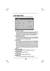
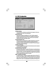
... Technology To enable this item appear to execute code. Intel (R) Virtualization tech. The C1 state is an enhancement to keep the CPU from being used by Vanderpool Technology. Set to [Enabled], a VMM (Virtual Machine Architecture) can prevent data pages from overheated. ...Threading technology and an operating system that includes optimization for this motherboard. 3.4.1CPU Configuration BIOS SETUP UTILITY Advanced Configure advanded CPU settings Intel (R) Core (TM) CPU 870 @ 2.93GHz Frequency :2.93GHz Cache L1 :128 KB Cache L2 :1024 KB Cache L3 :8192 KB Ratio Status...
... Technology To enable this item appear to execute code. Intel (R) Virtualization tech. The C1 state is an enhancement to keep the CPU from being used by Vanderpool Technology. Set to [Enabled], a VMM (Virtual Machine Architecture) can prevent data pages from overheated. ...Threading technology and an operating system that includes optimization for this motherboard. 3.4.1CPU Configuration BIOS SETUP UTILITY Advanced Configure advanded CPU settings Intel (R) Core (TM) CPU 870 @ 2.93GHz Frequency :2.93GHz Cache L1 :128 KB Cache L2 :1024 KB Cache L3 :8192 KB Ratio Status...
User Manual
Page 51
...to enable in which each core can request any C-state it wishes, thus allowing for individual core savings to enable or disable A20M. The CPU C-state is achieved by making the power and thermal control unit part of the core logic and not part of the power and thermal ... register. to the chipset power management hardware and flows. Active Processor Cores Use this item to select the number of both cores' requests, portraying a single CPU entity to [Enabled]. Intel (R) SpeedStep(tm) tech. If you set this item to [Disable] if above issue occurs. Please set the item "Intel (R) C-...
...to enable in which each core can request any C-state it wishes, thus allowing for individual core savings to enable or disable A20M. The CPU C-state is achieved by making the power and thermal control unit part of the core logic and not part of the power and thermal ... register. to the chipset power management hardware and flows. Active Processor Cores Use this item to select the number of both cores' requests, portraying a single CPU entity to [Enabled]. Intel (R) SpeedStep(tm) tech. If you set this item to [Disable] if above issue occurs. Please set the item "Intel (R) C-...
User Manual
Page 60
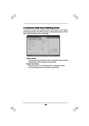
... Setting This allows you to monitor the status of the hardware on your system, including the parameters of the CPU temperature, motherboard temperature, CPU fan speed, chassis fan speed, and the critical voltage. 3.5 Hardware Health Event Monitoring Screen In this section,... speed. BIOS SETUP UTILITY Main OC Tweaker Advanced H/W Monitor Boot Security Exit Hardware Health Event Monitoring CPU Temperature M/B Temperature CPU Fan Speed Chassis Fan Speed Power Fan Speed Vcore + 3.30V + 5.00V + 12.00V CPU Fan Setting Chassis Fan Setting : 37 C / 98 F : 31 C / 87 F : N/A : N/A : N/A : 1.152V : ...
... Setting This allows you to monitor the status of the hardware on your system, including the parameters of the CPU temperature, motherboard temperature, CPU fan speed, chassis fan speed, and the critical voltage. 3.5 Hardware Health Event Monitoring Screen In this section,... speed. BIOS SETUP UTILITY Main OC Tweaker Advanced H/W Monitor Boot Security Exit Hardware Health Event Monitoring CPU Temperature M/B Temperature CPU Fan Speed Chassis Fan Speed Power Fan Speed Vcore + 3.30V + 5.00V + 12.00V CPU Fan Setting Chassis Fan Setting : 37 C / 98 F : 31 C / 87 F : N/A : N/A : N/A : 1.152V : ...


