User Manual
Page 3
... 5 1.1 Package Contents 5 1.2 Specifications 6 1.3 Motherboard Layout 9 1.4 ASRock 8CH I/O Plus 10 2 Installation 11 Pre-installation Precautions 11 2.1 CPU Installation 12 2.2 Installation of CPU Fan and Heatsink 12 2.3 Installation of Memory Modules (DIMM 13 2.4 Expansion... 22 3.1.1 BIOS Menu Bar 22 3.1.2 Navigation Keys 23 3.2 Main Screen 23 3.3 Smart Screen 24 3.4 Advanced Screen 25 3.4.1 CPU Configuration 25 3.4.2 Chipset Configuration 27 3.4.3 ACPI Configuration 30 3.4.4 IDE Configuration 31 3.4.5 PCIPnP Configuration 33 3.4.6 Floppy Configuration 34 3.4.7 ...
... 5 1.1 Package Contents 5 1.2 Specifications 6 1.3 Motherboard Layout 9 1.4 ASRock 8CH I/O Plus 10 2 Installation 11 Pre-installation Precautions 11 2.1 CPU Installation 12 2.2 Installation of CPU Fan and Heatsink 12 2.3 Installation of Memory Modules (DIMM 13 2.4 Expansion... 22 3.1.1 BIOS Menu Bar 22 3.1.2 Navigation Keys 23 3.2 Main Screen 23 3.3 Smart Screen 24 3.4 Advanced Screen 25 3.4.1 CPU Configuration 25 3.4.2 Chipset Configuration 27 3.4.3 ACPI Configuration 30 3.4.4 IDE Configuration 31 3.4.5 PCIPnP Configuration 33 3.4.6 Floppy Configuration 34 3.4.7 ...
User Manual
Page 5
...our website for purchasing ASRock P4i945GC motherboard, a reliable motherboard produced under ASRock's consistently stringent quality control. ASRock website http://www.asrock.com If you are using. www.asrock.com/support/index.asp 1.1 Package Contents ASRock P4i945GC Motherboard (Micro ATX Form Factor: 9.6-in x 7.7-in, 24.4 cm x 19.6 cm) ASRock P4i945GC Quick Installation Guide ASRock P4i945GC Support CD One 80... information of the motherboard and step-bystep guide to quality and endurance. You may find the latest VGA cards and CPU support lists on ASRock website without notice.
...our website for purchasing ASRock P4i945GC motherboard, a reliable motherboard produced under ASRock's consistently stringent quality control. ASRock website http://www.asrock.com If you are using. www.asrock.com/support/index.asp 1.1 Package Contents ASRock P4i945GC Motherboard (Micro ATX Form Factor: 9.6-in x 7.7-in, 24.4 cm x 19.6 cm) ASRock P4i945GC Quick Installation Guide ASRock P4i945GC Support CD One 80... information of the motherboard and step-bystep guide to quality and endurance. You may find the latest VGA cards and CPU support lists on ASRock website without notice.
User Manual
Page 6
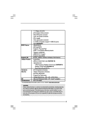
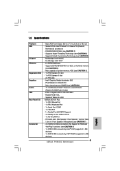
Max. Supports Wake-On-LAN ASRock 8CH I /O Connector - HD Audio Jack: Side Speaker / Rear Speaker / Central / Bass / Line in , 24.4 cm x 19.6 cm - Socket 478 for RAID and "Hot Plug" functions) (... memory 224MB (see CAUTION 1) - FSB 800/533/400 MHz (see CAUTION 6) - 7.1 CH Windows® VistaTM Premium Level HD Audio (Realtek ALC888 Audio Codec) - 1.2 Specifications Platform CPU Chipset Memory Expansion Slot Graphics Audio LAN Rear Panel I /O Plus - 1 x PS/2 Mouse Port - 1 x PS/2 Keyboard Port - 1 x Serial Port: COM1 - 1 x VGA Port - 1 x Parallel Port (ECP/EPP...
Max. Supports Wake-On-LAN ASRock 8CH I /O Connector - HD Audio Jack: Side Speaker / Rear Speaker / Central / Bass / Line in , 24.4 cm x 19.6 cm - Socket 478 for RAID and "Hot Plug" functions) (... memory 224MB (see CAUTION 1) - FSB 800/533/400 MHz (see CAUTION 6) - 7.1 CH Windows® VistaTM Premium Level HD Audio (Realtek ALC888 Audio Codec) - 1.2 Specifications Platform CPU Chipset Memory Expansion Slot Graphics Audio LAN Rear Panel I /O Plus - 1 x PS/2 Mouse Port - 1 x PS/2 Keyboard Port - 1 x Serial Port: COM1 - 1 x VGA Port - 1 x Parallel Port (ECP/EPP...
User Manual
Page 7
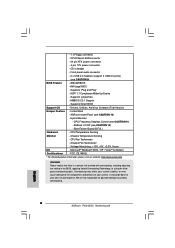
...174; 2000 / XP / VistaTM compliant Certifications - FCC, CE, WHQL * For detailed product information, please visit our website: http://www.asrock.com WARNING Please realize that there is a certain risk involved with overclocking, including adjusting the setting in header - It should be done ...even cause damage to the components and devices of your own risk and expense. ASRock Instant Flash (see CAUTION 11) - Voltage Monitoring: +12V, +5V, +3.3V, Vcore OS - AMI Legal BIOS - - 1 x Floppy connector - CPU/Chassis FAN connector - 24 pin ATX power connector - 4 pin 12V power ...
...174; 2000 / XP / VistaTM compliant Certifications - FCC, CE, WHQL * For detailed product information, please visit our website: http://www.asrock.com WARNING Please realize that there is a certain risk involved with overclocking, including adjusting the setting in header - It should be done ...even cause damage to the components and devices of your own risk and expense. ASRock Instant Flash (see CAUTION 11) - Voltage Monitoring: +12V, +5V, +3.3V, Vcore OS - AMI Legal BIOS - - 1 x Floppy connector - CPU/Chassis FAN connector - 24 pin ATX power connector - 4 pin 12V power ...
User Manual
Page 8
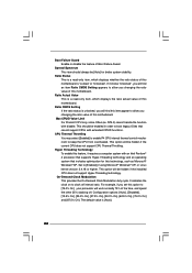
...update tool allows you can press key during the POST or press key to BIOS setup menu to change. ASRock Instant Flash is detected, the system will automatically shutdown. While CPU overheat is a BIOS flash utility embedded in a few clicks without entering operating systems first like MS-DOS ...SATAII mode. Just launch this utility, you resume the system, please check if the CPU fan on the motherboard functions properly and unplug the power cord, then plug it is subject to access ASRock Instant Flash. Before you can update your SATAII hard disk drive to update system ...
...update tool allows you can press key during the POST or press key to BIOS setup menu to change. ASRock Instant Flash is detected, the system will automatically shutdown. While CPU overheat is a BIOS flash utility embedded in a few clicks without entering operating systems first like MS-DOS ...SATAII mode. Just launch this utility, you resume the system, please check if the CPU fan on the motherboard functions properly and unplug the power cord, then plug it is subject to access ASRock Instant Flash. Before you can update your SATAII hard disk drive to update system ...
User Manual
Page 9
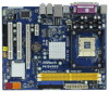
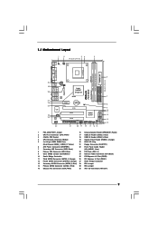
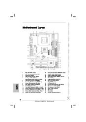
... 29 28 USB 2.0 T: USB2 B: USB3 ATX12V1 1 FD0 1 FD2 USB 2.0 T: USB0 B: USB1 Top: RJ-45 Intel 945GC Chipset Dual Channel P4i945GC Gigabit LAN Top: SIDE SPK Center: REAR SPK Bottom: CTR BASS 27 26 25 24 23 Top: LINE IN Center: FRONT Bottom: MIC IN RoHS...6 7 8 9 10 11 12 13 14 1 PS2_USB_PWR1 Jumper 16 Chassis Speaker Header (SPEAKER 1, Purple) 2 CPU Fan Connector (CPU_FAN1) 17 USB 2.0 Header (USB6_7, Blue) 3 478-Pin CPU Socket 18 USB 2.0 Header (USB4_5, Blue) 4 CPU Heatsink Retention Module 19 System Panel Header (PANEL1, Orange) 5 2 x 240-pin DDR2 DIMM Slots 20 BIOS ...
... 29 28 USB 2.0 T: USB2 B: USB3 ATX12V1 1 FD0 1 FD2 USB 2.0 T: USB0 B: USB1 Top: RJ-45 Intel 945GC Chipset Dual Channel P4i945GC Gigabit LAN Top: SIDE SPK Center: REAR SPK Bottom: CTR BASS 27 26 25 24 23 Top: LINE IN Center: FRONT Bottom: MIC IN RoHS...6 7 8 9 10 11 12 13 14 1 PS2_USB_PWR1 Jumper 16 Chassis Speaker Header (SPEAKER 1, Purple) 2 CPU Fan Connector (CPU_FAN1) 17 USB 2.0 Header (USB6_7, Blue) 3 478-Pin CPU Socket 18 USB 2.0 Header (USB4_5, Blue) 4 CPU Heatsink Retention Module 19 System Panel Header (PANEL1, Orange) 5 2 x 240-pin DDR2 DIMM Slots 20 BIOS ...

User Manual
Page 12
... fastened and in place, press it firmly on the side tab to support Intel® Pentium®4 CPU. Step 3. Carefully insert the CPU into the socket to improve heat dissipation. The CPU fits only in place. Make sure that its marked corner matches the base of the pins. DO NOT...refer to the CPU_FAN connector (CPU_FAN1, see page 9, No. 2). Unlock the socket by lifting the lever up to secure the CPU. When the CPU is locked. Lift Lever Up to 90° CPU Marked Corner Socket Marked Corner STEP 1: Lift The Socket Lever Up to 90° STEP 2/STEP 3: Match The...
... fastened and in place, press it firmly on the side tab to support Intel® Pentium®4 CPU. Step 3. Carefully insert the CPU into the socket to improve heat dissipation. The CPU fits only in place. Make sure that its marked corner matches the base of the pins. DO NOT...refer to the CPU_FAN connector (CPU_FAN1, see page 9, No. 2). Unlock the socket by lifting the lever up to secure the CPU. When the CPU is locked. Lift Lever Up to 90° CPU Marked Corner Socket Marked Corner STEP 1: Lift The Socket Lever Up to 90° STEP 2/STEP 3: Match The...
User Manual
Page 15
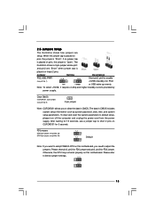
... seconds, use a jumper cap to enable +5VSB (standby) for 5 seconds. Please short pin2, pin3 for FD0 jumper and pin2, pin3 for FD2 jumper. Otherwise, the CPU may not work properly on this motherboard, you want to adjust the jumpers. If no jumper cap is placed on pins, the jumper is "Short...". Clear CMOS (CLRCMOS1, 2-pin jumper) (see p.9 No. 28) 1_2 1_2 Default Note: If you need to adopt FSB400-CPU on this motherboard. 2.5 Jumpers Setup The illustration shows how jumpers are "Short" when jumper cap is placed on these 2 pins.
... seconds, use a jumper cap to enable +5VSB (standby) for 5 seconds. Please short pin2, pin3 for FD0 jumper and pin2, pin3 for FD2 jumper. Otherwise, the CPU may not work properly on this motherboard, you want to adjust the jumpers. If no jumper cap is placed on pins, the jumper is "Short...". Clear CMOS (CLRCMOS1, 2-pin jumper) (see p.9 No. 28) 1_2 1_2 Default Note: If you need to adopt FSB400-CPU on this motherboard. 2.5 Jumpers Setup The illustration shows how jumpers are "Short" when jumper cap is placed on these 2 pins.
User Manual
Page 18
... a chassis fan cable to this connector and match the black wire to make the Front Mic as default record device. CPU Fan Connector (3-pin CPU_FAN1) (see p.9 No. 2) GND +12V CPU_FAN_SPEED Please connect a CPU fan cable to the "Front Mic" Tab in "Front Mic" of "Playback" portion. Click "Set Default Device" to the...
... a chassis fan cable to this connector and match the black wire to make the Front Mic as default record device. CPU Fan Connector (3-pin CPU_FAN1) (see p.9 No. 2) GND +12V CPU_FAN_SPEED Please connect a CPU fan cable to the "Front Mic" Tab in "Front Mic" of "Playback" portion. Click "Set Default Device" to the...
User Manual
Page 21
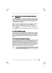
Therefore, CPU FSB is untied during overclocking, FSB enjoys better margin due to the SATA / SATAII hard disk. Please refer to the warning on page 7 for internal ... SATA / SATAII hard disks into the drive bays of the SATA data cable to install the SATA / SATAII hard disks. Then, the drivers compatible to [CPU, PCIE, Async.]. Please follow the order from [Auto] to your system can operate under a more stable overclocking environment.
Therefore, CPU FSB is untied during overclocking, FSB enjoys better margin due to the SATA / SATAII hard disk. Please refer to the warning on page 7 for internal ... SATA / SATAII hard disks into the drive bays of the SATA data cable to install the SATA / SATAII hard disks. Then, the drivers compatible to [CPU, PCIE, Async.]. Please follow the order from [Auto] to your system can operate under a more stable overclocking environment.
User Manual
Page 23
... Main Smart Advanced H/W Monitor Boot Security Exit System Overview System Time System Date [14:00:09] [Wed 06/10/2009] BIOS Version : P4i945GC P1.00 Processor Type : Intel (R) Celeron (R) CPU 2.60GHz Processor Speed : 2600MHz Microcode Update : F29/2E Cache Size : 128KB Total Memory DDRII1 DDRII2 : 512MB with 8MB shared memory Single-Channel...
... Main Smart Advanced H/W Monitor Boot Security Exit System Overview System Time System Date [14:00:09] [Wed 06/10/2009] BIOS Version : P4i945GC P1.00 Processor Type : Intel (R) Celeron (R) CPU 2.60GHz Processor Speed : 2600MHz Microcode Update : F29/2E Cache Size : 128KB Total Memory DDRII1 DDRII2 : 512MB with 8MB shared memory Single-Channel...
User Manual
Page 25
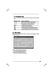
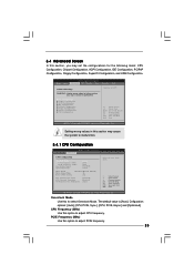
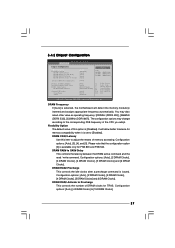
...[Enabled] [Auto] Ratio Status Ratio Actual Value Ratio CMOS Setting Unlocked (Min:16, Max:26) 26 [26] Max CPUID Value Limit CPU Thermal Throttling On-Demand Clock Mudulation [Disabled] [Enabled] [Auto] Select the over clock mode. +F1 F9 F10 ESC Select Screen Select Item... Use this option to adjust PCIE frequency. 25 3.4 Advanced Screen In this section, you may set the configurations for CPU CPU Configuration Chipset Configuration ACPI Configuration IDE Configuration PCIPnP Configuration Floppy Configuration SuperIO Configuration USB Configuration Select Screen Select Item Enter Go ...
...[Enabled] [Auto] Ratio Status Ratio Actual Value Ratio CMOS Setting Unlocked (Min:16, Max:26) 26 [26] Max CPUID Value Limit CPU Thermal Throttling On-Demand Clock Mudulation [Disabled] [Enabled] [Auto] Select the over clock mode. +F1 F9 F10 ESC Select Screen Select Item... Use this option to adjust PCIE frequency. 25 3.4 Advanced Screen In this section, you may set the configurations for CPU CPU Configuration Chipset Configuration ACPI Configuration IDE Configuration PCIPnP Configuration Floppy Configuration SuperIO Configuration USB Configuration Select Screen Select Item Enter Go ...
User Manual
Page 26
... with disable. On-Demand Clock Modulation This provides the On-Demand Clock Modulation duty cycle. This should always be hidden if the installed CPU does not support Hyper-Threading technology. Ratio CMOS Setting If the ratio status is [Auto]. 26 This option will be [Auto] for... [Disabled], [12.5% On], [25.0% On], [37.5% On], [50.0% On], [62.5% On], [75.0% On] and [87.5% On]. Max CPUID Value Limit For Prescott CPU only, some OSes (ex. Boot Failure Guard Enable or disable the feature of this motherboard. Hyper Threading Technology To enable this feature, it shows "Unlocked...
... with disable. On-Demand Clock Modulation This provides the On-Demand Clock Modulation duty cycle. This should always be hidden if the installed CPU does not support Hyper-Threading technology. Ratio CMOS Setting If the ratio status is [Auto]. 26 This option will be [Auto] for... [Disabled], [12.5% On], [25.0% On], [37.5% On], [50.0% On], [62.5% On], [75.0% On] and [87.5% On]. Max CPUID Value Limit For Prescott CPU only, some OSes (ex. Boot Failure Guard Enable or disable the feature of this motherboard. Hyper Threading Technology To enable this feature, it shows "Unlocked...
User Manual
Page 27
... command. Configuration options: [Auto], [2 DRAM Clocks], [3 DRAM Clocks], [4 DRAM Clocks], [5 DRAM Clocks] and [6 DRAM Clocks]. DRAM RAS# to Precharge This controls the number of the CPU you adopt.
... command. Configuration options: [Auto], [2 DRAM Clocks], [3 DRAM Clocks], [4 DRAM Clocks], [5 DRAM Clocks] and [6 DRAM Clocks]. DRAM RAS# to Precharge This controls the number of the CPU you adopt.
User Manual
Page 36
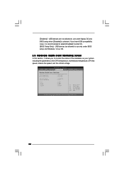
... speed, chassis fan speed, and the critical voltage. BIOS SETUP UTILITY Main Smart Advanced H/W Monitor Boot Security Exit Hardware Health Event Monitoring CPU Temperature M / B Temperature CPU Fan Speed Chassis Fan Speed Vcore + 3.30V + 5.00V + 12.00V : 37 C / 98 F : 31 C / 87 F : 3400 RPM : N/A : 1.629V : 3.306V : 5.067V : 11.890V F1 F9 F10 ESC ...
... speed, chassis fan speed, and the critical voltage. BIOS SETUP UTILITY Main Smart Advanced H/W Monitor Boot Security Exit Hardware Health Event Monitoring CPU Temperature M / B Temperature CPU Fan Speed Chassis Fan Speed Vcore + 3.30V + 5.00V + 12.00V : 37 C / 98 F : 31 C / 87 F : 3400 RPM : N/A : 1.629V : 3.306V : 5.067V : 11.890V F1 F9 F10 ESC ...
Quick Installation Guide
Page 2
... Jumper 16 Chassis Speaker Header (SPEAKER 1, Purple) 2 CPU Fan Connector (CPU_FAN1) 17 USB 2.0 Header (USB6_7, Blue) 3 478-Pin CPU Socket 18 USB 2.0 Header (USB4_5, Blue) 4 CPU Heatsink Retention Module 19 System Panel Header (PANEL1, Orange)... 5 2 x 240-pin DDR2 DIMM Slots 20 BIOS SPI Chip (Dual Channel: DDRII_1, DDRII_2; Orange) 26 PCI Express x1 Slot (PCIE1) 12 Fourth SATAII Connector (SATAII_4; Red) 29 FD0 Jumper 15 Chassis Fan Connector (CHA_FAN1) 30 ATX 12V Connector (ATX12V1) 2 ASRock P4i945GC...
... Jumper 16 Chassis Speaker Header (SPEAKER 1, Purple) 2 CPU Fan Connector (CPU_FAN1) 17 USB 2.0 Header (USB6_7, Blue) 3 478-Pin CPU Socket 18 USB 2.0 Header (USB4_5, Blue) 4 CPU Heatsink Retention Module 19 System Panel Header (PANEL1, Orange)... 5 2 x 240-pin DDR2 DIMM Slots 20 BIOS SPI Chip (Dual Channel: DDRII_1, DDRII_2; Orange) 26 PCI Express x1 Slot (PCIE1) 12 Fourth SATAII Connector (SATAII_4; Red) 29 FD0 Jumper 15 Chassis Fan Connector (CHA_FAN1) 30 ATX 12V Connector (ATX12V1) 2 ASRock P4i945GC...
Quick Installation Guide
Page 4
... 80-conductor Ultra ATA IDE Ribbon Cable (Optional) One Serial ATA (SATA) Data Cable (Optional) One I/O Panel Shield 4 ASRock P4i945GC Motherboard English You may find the latest VGA cards and CPU support lists on ASRock website without notice. Because the motherboard specifications and the BIOS software might be updated, the content of this manual...
... 80-conductor Ultra ATA IDE Ribbon Cable (Optional) One Serial ATA (SATA) Data Cable (Optional) One I/O Panel Shield 4 ASRock P4i945GC Motherboard English You may find the latest VGA cards and CPU support lists on ASRock website without notice. Because the motherboard specifications and the BIOS software might be updated, the content of this manual...
Quick Installation Guide
Page 5
...- Northbridge: Intel® 945GC - Southbridge: Intel® ICH7 - 2 x DDR2 DIMM slots - Pixel Shader 2.0, DirectX 9.0 - Supports Wake-On-LAN ASRock 8CH I /O Connector - 1.2 Specifications Platform CPU Chipset Memory Expansion Slot Graphics Audio LAN Rear Panel I /O Plus - 1 x PS/2 Mouse Port - 1 x PS/2 Keyboard Port - 1 x Serial...ICH7 (supports 2 x IDE devices) - 1 x ATA133 IDE connector by VIA® VT6415 (supports 2 x IDE devices) 5 ASRock P4i945GC Motherboard English Max. PCIE x1 Gigabit LAN 10/100/1000 Mb/s - Max. Supports DDR2 667/533/400 non-ECC, un-buffered memory ...
...- Northbridge: Intel® 945GC - Southbridge: Intel® ICH7 - 2 x DDR2 DIMM slots - Pixel Shader 2.0, DirectX 9.0 - Supports Wake-On-LAN ASRock 8CH I /O Connector - 1.2 Specifications Platform CPU Chipset Memory Expansion Slot Graphics Audio LAN Rear Panel I /O Plus - 1 x PS/2 Mouse Port - 1 x PS/2 Keyboard Port - 1 x Serial...ICH7 (supports 2 x IDE devices) - 1 x ATA133 IDE connector by VIA® VT6415 (supports 2 x IDE devices) 5 ASRock P4i945GC Motherboard English Max. PCIE x1 Gigabit LAN 10/100/1000 Mb/s - Max. Supports DDR2 667/533/400 non-ECC, un-buffered memory ...
Quick Installation Guide
Page 6
... OS - We are not responsible for possible damage caused by overclocking. English 6 ASRock P4i945GC Motherboard CPU/Chassis FAN connector - 24 pin ATX power connector - 4 pin 12V power connector - CPU Fan Tachometer - Overclocking may affect your system stability, or even cause damage to ... Stepless Control (see CAUTION 12) - CPU Temperature Sensing Monitor - Chassis Temperature Sensing - Chassis Fan Tachometer - FCC, CE, WHQL * For detailed product information, please visit our website: http://www.asrock.com WARNING Please realize that there is a certain...
... OS - We are not responsible for possible damage caused by overclocking. English 6 ASRock P4i945GC Motherboard CPU/Chassis FAN connector - 24 pin ATX power connector - 4 pin 12V power connector - CPU Fan Tachometer - Overclocking may affect your system stability, or even cause damage to ... Stepless Control (see CAUTION 12) - CPU Temperature Sensing Monitor - Chassis Temperature Sensing - Chassis Fan Tachometer - FCC, CE, WHQL * For detailed product information, please visit our website: http://www.asrock.com WARNING Please realize that there is a certain...
Quick Installation Guide
Page 7
... back again. Please be less than the recommended CPU bus frequencies may be noted that the USB flash drive or hard drive must use FAT32/16/12 file system. 11. Although this utility, you install the PC system. 7 ASRock P4i945GC Motherboard English To improve heat dissipation, remember to ...spray thermal grease between the CPU and the heatsink when you can press key during the POST or press key to BIOS setup ...
... back again. Please be less than the recommended CPU bus frequencies may be noted that the USB flash drive or hard drive must use FAT32/16/12 file system. 11. Although this utility, you install the PC system. 7 ASRock P4i945GC Motherboard English To improve heat dissipation, remember to ...spray thermal grease between the CPU and the heatsink when you can press key during the POST or press key to BIOS setup ...


