User Manual
Page 3
... CPU Fan and Heatsink 12 2.3 Installation of Memory Modules (DIMM 13 2.4 Expansion Slots (PCI and PCI Express Slots 14 2.5 Jumpers Setup 15 2.6 Onboard Headers and Connectors 16 2.7 SATAII Hard Disk Setup Guide 20 2.8 Serial ATA (SATA) / Serial ATAII (SATAII) Hard Disks Installation 21 2.9 Driver Installation Guide 21 2.10 Untied Overclocking Technology 21 3 BIOS SETUP UTILITY 22 3.1 Introduction 22 3.1.1 BIOS Menu Bar 22 3.1.2 Navigation Keys 23 3.2 Main Screen 23 3.3 Smart Screen 24 3.4 Advanced Screen 25 3.4.1 CPU Configuration 25 3.4.2 Chipset Configuration 27 3.4.3 ACPI...
... CPU Fan and Heatsink 12 2.3 Installation of Memory Modules (DIMM 13 2.4 Expansion Slots (PCI and PCI Express Slots 14 2.5 Jumpers Setup 15 2.6 Onboard Headers and Connectors 16 2.7 SATAII Hard Disk Setup Guide 20 2.8 Serial ATA (SATA) / Serial ATAII (SATAII) Hard Disks Installation 21 2.9 Driver Installation Guide 21 2.10 Untied Overclocking Technology 21 3 BIOS SETUP UTILITY 22 3.1 Introduction 22 3.1.1 BIOS Menu Bar 22 3.1.2 Navigation Keys 23 3.2 Main Screen 23 3.3 Smart Screen 24 3.4 Advanced Screen 25 3.4.1 CPU Configuration 25 3.4.2 Chipset Configuration 27 3.4.3 ACPI...
User Manual
Page 7
...Chassis Fan Tachometer - CPU/Chassis FAN connector - 24 pin ATX power connector - 4 pin 12V power connector - CD in the BIOS, applying Untied Overclocking Technology, or using the thirdparty overclocking tools. AMBIOS 2.3.1 Support - Voltage Monitoring: +12V, +5V, +3.3V, Vcore OS - - 1 x Floppy connector - AMI Legal BIOS - Supports "Plug and Play" - Supports Smart BIOS Support CD - Instant Boot - Hybrid Booster: - CPU Frequency Stepless Control (see CAUTION 9) BIOS Feature - 4Mb AMI BIOS - Boot Failure Guard (B.F.G.) Hardware - Microsoft® Windows...
...Chassis Fan Tachometer - CPU/Chassis FAN connector - 24 pin ATX power connector - 4 pin 12V power connector - CD in the BIOS, applying Untied Overclocking Technology, or using the thirdparty overclocking tools. AMBIOS 2.3.1 Support - Voltage Monitoring: +12V, +5V, +3.3V, Vcore OS - - 1 x Floppy connector - AMI Legal BIOS - Supports "Plug and Play" - Supports Smart BIOS Support CD - Instant Boot - Hybrid Booster: - CPU Frequency Stepless Control (see CAUTION 9) BIOS Feature - 4Mb AMI BIOS - Boot Failure Guard (B.F.G.) Hardware - Microsoft® Windows...
User Manual
Page 8
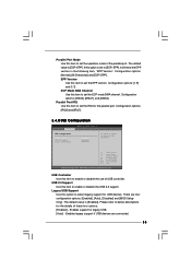
... also connect SATA hard disk to update system BIOS without prepar- Just launch this motherboard offers stepless control, it back again. Please be less than the recommended CPU bus frequencies may be noted that the USB flash drive or hard drive must use FAT32/16/12 file system. 11. Although this tool and save the new BIOS file to your BIOS only in Flash ROM. This motherboard supports Untied Overclocking Technology. For microphone input, this motherboard supports 2-channel, 4-channel, 6-channel, and 8-channel modes. The...
... also connect SATA hard disk to update system BIOS without prepar- Just launch this motherboard offers stepless control, it back again. Please be less than the recommended CPU bus frequencies may be noted that the USB flash drive or hard drive must use FAT32/16/12 file system. 11. Although this tool and save the new BIOS file to your BIOS only in Flash ROM. This motherboard supports Untied Overclocking Technology. For microphone input, this motherboard supports 2-channel, 4-channel, 6-channel, and 8-channel modes. The...
User Manual
Page 9
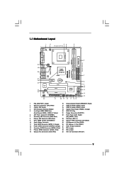
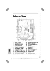
... Intel ICH7 4Mb PANEL 1 PLED PWRBTN BIOS 1 1 HDLED RESET USB4_5 USB6_7 1 CHA_FAN1 SPEAKER1 1 20 19 18 17 16 15 SATAII_2 SATAII_4 24.4cm (9.6 in) 6 7 8 9 10 11 12 13 14 1 PS2_USB_PWR1 Jumper 16 Chassis Speaker Header (SPEAKER 1, Purple) 2 CPU Fan Connector (CPU_FAN1) 17 USB 2.0 Header (USB6_7, Blue) 3 478-Pin CPU Socket 18 USB 2.0 Header (USB4_5, Blue) 4 CPU Heatsink Retention Module 19 System Panel Header (PANEL1, Orange) 5 2 x 240-pin DDR2 DIMM Slots 20 BIOS SPI Chip (Dual Channel: DDRII_1, DDRII_2...
... Intel ICH7 4Mb PANEL 1 PLED PWRBTN BIOS 1 1 HDLED RESET USB4_5 USB6_7 1 CHA_FAN1 SPEAKER1 1 20 19 18 17 16 15 SATAII_2 SATAII_4 24.4cm (9.6 in) 6 7 8 9 10 11 12 13 14 1 PS2_USB_PWR1 Jumper 16 Chassis Speaker Header (SPEAKER 1, Purple) 2 CPU Fan Connector (CPU_FAN1) 17 USB 2.0 Header (USB6_7, Blue) 3 478-Pin CPU Socket 18 USB 2.0 Header (USB4_5, Blue) 4 CPU Heatsink Retention Module 19 System Panel Header (PANEL1, Orange) 5 2 x 240-pin DDR2 DIMM Slots 20 BIOS SPI Chip (Dual Channel: DDRII_1, DDRII_2...
User Manual
Page 17
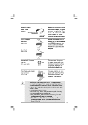
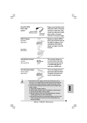
... header as a CD-ROM, DVD-ROM, TV tuner card, or MPEG card. Enter Advanced Settings, and then select Chipset Configuration. Front Panel Audio Header (9-pin HD_AUDIO1) (see p.9 No. 24) USB_PWR P-7 P+7 GND DUMMY 1 GND P+6 P-6 USB_PWR USB_PWR P-5 P+5 GND DUMMY 1 GND P+4 P-4 USB_PWR CD1 CD-L GND GND CD-R Please connect the black end of audio devices. 1. E. If you to receive stereo audio input from [Auto] to OUT2_L. Enter BIOS Setup Utility. Serial ATA (SATA) Power Cable (Optional) connect to the SATA HDD power connector connect to the power supply USB 2.0 Headers (9-pin...
... header as a CD-ROM, DVD-ROM, TV tuner card, or MPEG card. Enter Advanced Settings, and then select Chipset Configuration. Front Panel Audio Header (9-pin HD_AUDIO1) (see p.9 No. 24) USB_PWR P-7 P+7 GND DUMMY 1 GND P+6 P-6 USB_PWR USB_PWR P-5 P+5 GND DUMMY 1 GND P+4 P-4 USB_PWR CD1 CD-L GND GND CD-R Please connect the black end of audio devices. 1. E. If you to receive stereo audio input from [Auto] to OUT2_L. Enter BIOS Setup Utility. Serial ATA (SATA) Power Cable (Optional) connect to the SATA HDD power connector connect to the power supply USB 2.0 Headers (9-pin...
User Manual
Page 20
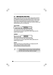
... instruction with the best performance. SAMSUNG 7531 8642 If pin 3 and pin 4 are shorted, SATA 1.5Gb/s will be enabled. Please visit HITACHI's website for details: http://www.hitachigst.com/hdd/support/download.htm The above examples are just for your SATAII hard disk to SATAII mode in advance; Please visit the vendors' website for changing various ATA features. Some default setting of different vendors, the jumper pin setting...
... instruction with the best performance. SAMSUNG 7531 8642 If pin 3 and pin 4 are shorted, SATA 1.5Gb/s will be enabled. Please visit HITACHI's website for details: http://www.hitachigst.com/hdd/support/download.htm The above examples are just for your SATAII hard disk to SATAII mode in advance; Please visit the vendors' website for changing various ATA features. Some default setting of different vendors, the jumper pin setting...
User Manual
Page 21
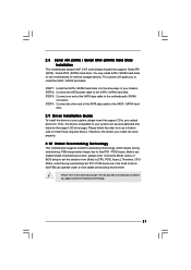
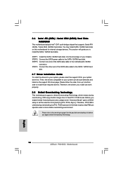
... [Auto] to install those required drivers. You may install SATA / SATAII hard disks on page 7 for internal storage devices. Before you apply Untied Overclocking Technology. 21 STEP 2: Connect the SATA power cable to the motherboard's SATAII connector. 2.8 Serial ATA (SATA) / Serial ATAII (SATAII) Hard Disks Installation This motherboard adopts Intel® ICH7 south bridge chipset that FSB can operate under a more stable overclocking environment. STEP 3: Connect one end of BIOS setup to set the selection from up to bottom side to [CPU, PCIE...
... [Auto] to install those required drivers. You may install SATA / SATAII hard disks on page 7 for internal storage devices. Before you apply Untied Overclocking Technology. 21 STEP 2: Connect the SATA power cable to the motherboard's SATAII connector. 2.8 Serial ATA (SATA) / Serial ATAII (SATAII) Hard Disks Installation This motherboard adopts Intel® ICH7 south bridge chipset that FSB can operate under a more stable overclocking environment. STEP 3: Connect one end of BIOS setup to set the selection from up to bottom side to [CPU, PCIE...
User Manual
Page 26
... disable. CPU Thermal Throttling You may select [Enabled] to enable P4 CPU internal thermal control mechanism to [Enabled] if using Microsoft® Windows® XP, or Linux kernel version 2.4.18 or higher. For example, if you set this motherboard. This should always be enabled in order to allow you changing the ratio value of this option to [75.0% On], your processor will find this item appear to boot legacy...
... disable. CPU Thermal Throttling You may select [Enabled] to enable P4 CPU internal thermal control mechanism to [Enabled] if using Microsoft® Windows® XP, or Linux kernel version 2.4.18 or higher. For example, if you set this motherboard. This should always be enabled in order to allow you changing the ratio value of this option to [75.0% On], your processor will find this item appear to boot legacy...

User Manual
Page 28
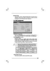
... of Onboard HD Audio. CD-In Use this item to enable or disable CD-In of memory is allocated to adjust advanced DRAM configuration. Onboard HD Audio Select [Auto], [Enabled] or [Disabled] for the onboard HD Audio Front Panel. The default value is [PCI]. Configuration options: [Onboard], [PCI] and [PCI Express]. Internal Graphics Mode Select If you select [Auto], the onboard VGA will be automatically disabled when you set DVMT Mode Select as needed for the motherboard through efficient memory utilization. If you to the graphics core. Configuration options: [64MB...
... of Onboard HD Audio. CD-In Use this item to enable or disable CD-In of memory is allocated to adjust advanced DRAM configuration. Onboard HD Audio Select [Auto], [Enabled] or [Disabled] for the onboard HD Audio Front Panel. The default value is [PCI]. Configuration options: [Onboard], [PCI] and [PCI Express]. Internal Graphics Mode Select If you select [Auto], the onboard VGA will be automatically disabled when you set DVMT Mode Select as needed for the motherboard through efficient memory utilization. If you to the graphics core. Configuration options: [64MB...
User Manual
Page 31
... supports four IDE devices under legacy OS (Windows® NT), you to enable or disable onboard IDE2 controller. 31 If it is used . +F1 F9 F10 ESC Select Screen Select Item Change Option General Help Load Defaults Save and Exit Exit v02.54 (C) Copyright 1985-2005, American Megatrends, Inc. If native OS (Windows® 2000 / XP) is [Disabled]. Please set to submit Windows® VistaTM certification. 3.4.4 IDE Configuration BIOS SETUP UTILITY Advanced IDE Configuration SATAII/IDE1 Configuration OnBoard...
... supports four IDE devices under legacy OS (Windows® NT), you to enable or disable onboard IDE2 controller. 31 If it is used . +F1 F9 F10 ESC Select Screen Select Item Change Option General Help Load Defaults Save and Exit Exit v02.54 (C) Copyright 1985-2005, American Megatrends, Inc. If native OS (Windows® 2000 / XP) is [Disabled]. Please set to submit Windows® VistaTM certification. 3.4.4 IDE Configuration BIOS SETUP UTILITY Advanced IDE Configuration SATAII/IDE1 Configuration OnBoard...
User Manual
Page 33
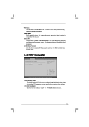
... Technology) feature. Use this item to set the PIO mode to keep the default value unless the installed PCI expansion cards' specifications require other settings. PCI Latency Timer The default value is recommended to enhance hard disk performance by optimizing the hard disk timing. It is 32. Configuration options: [Disabled], [Auto], [Enabled]. 32-Bit Data Transfer Use this item to maximize the IDE hard disk data transfer rate. 3.4.5 PCIPnP Configuration BIOS SETUP UTILITY Advanced Advanced PCI / PnP Settings PCI Latency Timer PCI IDE BusMaster [32] [Enabled...
... Technology) feature. Use this item to set the PIO mode to keep the default value unless the installed PCI expansion cards' specifications require other settings. PCI Latency Timer The default value is recommended to enhance hard disk performance by optimizing the hard disk timing. It is 32. Configuration options: [Disabled], [Auto], [Enabled]. 32-Bit Data Transfer Use this item to maximize the IDE hard disk data transfer rate. 3.4.5 PCIPnP Configuration BIOS SETUP UTILITY Advanced Advanced PCI / PnP Settings PCI Latency Timer PCI IDE BusMaster [32] [Enabled...
User Manual
Page 34
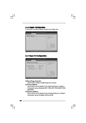
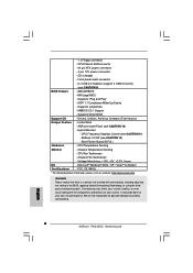
...of floppy drive connected to the system. +F1 F9 F10 ESC Select Screen Select Item Change Option General Help Load Defaults Save and Exit Exit v02.54 (C) Copyright 1985-2005, American Megatrends, Inc. 3.4.7 Super IO Configuration BIOS SETUP UTILITY Advanced Configure Super IO Chipset OnBoard Floppy Controller Serial Port Address Parallel Port Address Parallel Port Mode EPP Version ECP Mode DMA Channel Parallel Port IRQ [Enabled] [3F8 / IRQ4] [378] [ECP + EPP] [1.9] [DMA3] [IRQ7] Allow BIOS to enable or disable floppy drive controller. BIOS SETUP UTILITY Advanced Floppy Configuration...
...of floppy drive connected to the system. +F1 F9 F10 ESC Select Screen Select Item Change Option General Help Load Defaults Save and Exit Exit v02.54 (C) Copyright 1985-2005, American Megatrends, Inc. 3.4.7 Super IO Configuration BIOS SETUP UTILITY Advanced Configure Super IO Chipset OnBoard Floppy Controller Serial Port Address Parallel Port Address Parallel Port Mode EPP Version ECP Mode DMA Channel Parallel Port IRQ [Enabled] [3F8 / IRQ4] [378] [ECP + EPP] [1.9] [DMA3] [IRQ7] Allow BIOS to enable or disable floppy drive controller. BIOS SETUP UTILITY Advanced Floppy Configuration...
User Manual
Page 35
...item to set the ECP mode DMA channel. EPP Version Use this item to set the operation mode of these four options: [Enabled] - ECP Mode DMA Channel Use this item to enable or disable the USB 2.0 support. Configuration options: [DMA0], [DMA1], and [DMA3]. Configuration options: [IRQ5] and [IRQ7]. 3.4.8 USB Configuration BIOS SETUP UTILITY Advanced USB Configuration USB Controller USB 2.0 Support Legacy USB Support [Enabled] [Enabled] [Enabled] To enable or disable the onboard USB controllers. +F1 F9 F10 ESC Select Screen Select Item Change Option General Help Load Defaults Save...
...item to set the ECP mode DMA channel. EPP Version Use this item to set the operation mode of these four options: [Enabled] - ECP Mode DMA Channel Use this item to enable or disable the USB 2.0 support. Configuration options: [DMA0], [DMA1], and [DMA3]. Configuration options: [IRQ5] and [IRQ7]. 3.4.8 USB Configuration BIOS SETUP UTILITY Advanced USB Configuration USB Controller USB 2.0 Support Legacy USB Support [Enabled] [Enabled] [Enabled] To enable or disable the onboard USB controllers. +F1 F9 F10 ESC Select Screen Select Item Change Option General Help Load Defaults Save...
User Manual
Page 40
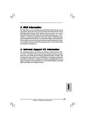
... displays the Main Menu if "AUTORUN" is enabled in your dealer for further information. 40 Because motherboard settings and hardware options vary, use the setup procedures in the Support CD to visit ASRock's website at http://www.asrock.com; Click on the file "ASSETUP.EXE" from the BIN folder in this chapter for more about ASRock, welcome to display the menus. 4.2.2 Drivers Menu The Drivers Menu shows the available devices drivers...
... displays the Main Menu if "AUTORUN" is enabled in your dealer for further information. 40 Because motherboard settings and hardware options vary, use the setup procedures in the Support CD to visit ASRock's website at http://www.asrock.com; Click on the file "ASSETUP.EXE" from the BIN folder in this chapter for more about ASRock, welcome to display the menus. 4.2.2 Drivers Menu The Drivers Menu shows the available devices drivers...
Quick Installation Guide
Page 2
... Connector (CHA_FAN1) 30 ATX 12V Connector (ATX12V1) 2 ASRock P4i945GC Motherboard Motherboard Layout English 1 PS2_USB_PWR1 Jumper 16 Chassis Speaker Header (SPEAKER 1, Purple) 2 CPU Fan Connector (CPU_FAN1) 17 USB 2.0 Header (USB6_7, Blue) 3 478-Pin CPU Socket 18 USB 2.0 Header (USB4_5, Blue) 4 CPU Heatsink Retention Module 19 System Panel Header (PANEL1, Orange) 5 2 x 240-pin DDR2 DIMM Slots 20 BIOS SPI Chip (Dual Channel: DDRII_1, DDRII_2; Yellow) 21 Floppy Connector (FLOPPY1) 6 ATX Power Connector (ATXPWR1) 22 Front Panel Audio Header 7 Secondary IDE Connector...
... Connector (CHA_FAN1) 30 ATX 12V Connector (ATX12V1) 2 ASRock P4i945GC Motherboard Motherboard Layout English 1 PS2_USB_PWR1 Jumper 16 Chassis Speaker Header (SPEAKER 1, Purple) 2 CPU Fan Connector (CPU_FAN1) 17 USB 2.0 Header (USB6_7, Blue) 3 478-Pin CPU Socket 18 USB 2.0 Header (USB4_5, Blue) 4 CPU Heatsink Retention Module 19 System Panel Header (PANEL1, Orange) 5 2 x 240-pin DDR2 DIMM Slots 20 BIOS SPI Chip (Dual Channel: DDRII_1, DDRII_2; Yellow) 21 Floppy Connector (FLOPPY1) 6 ATX Power Connector (ATXPWR1) 22 Front Panel Audio Header 7 Secondary IDE Connector...
Quick Installation Guide
Page 6
.../Chassis FAN connector - 24 pin ATX power connector - 4 pin 12V power connector - Chassis Fan Tachometer - Voltage Monitoring: +12V, +5V, +3.3V, Vcore OS - Overclocking may affect your system stability, or even cause damage to the components and devices of your own risk and expense. AMBIOS 2.3.1 Support - Drivers, Utilities, AntiVirus Software (Trial Version) Unique Feature - CPU Frequency Stepless Control (see CAUTION 9) BIOS Feature - 4Mb AMI BIOS - Boot Failure Guard (B.F.G.) Hardware - Instant Boot - ASRock U-COP (see CAUTION 10) - Chassis Temperature...
.../Chassis FAN connector - 24 pin ATX power connector - 4 pin 12V power connector - Chassis Fan Tachometer - Voltage Monitoring: +12V, +5V, +3.3V, Vcore OS - Overclocking may affect your system stability, or even cause damage to the components and devices of your own risk and expense. AMBIOS 2.3.1 Support - Drivers, Utilities, AntiVirus Software (Trial Version) Unique Feature - CPU Frequency Stepless Control (see CAUTION 9) BIOS Feature - 4Mb AMI BIOS - Boot Failure Guard (B.F.G.) Hardware - Instant Boot - ASRock U-COP (see CAUTION 10) - Chassis Temperature...
Quick Installation Guide
Page 7
... memory size is defined by the chipset vendor and is a BIOS flash utility embedded in the support CD. 3. You can also connect SATA hard disk to change. If you adopt FSB400-CPU on this utility, you install the PC system. 7 ASRock P4i945GC Motherboard English Please refer to adjust the jumpers. About the setting of "Hyper Threading Technology", please check page 26 of "User Manual" in the support CD to adjust your SATAII hard disk drive to your USB flash drive, floppy disk...
... memory size is defined by the chipset vendor and is a BIOS flash utility embedded in the support CD. 3. You can also connect SATA hard disk to change. If you adopt FSB400-CPU on this utility, you install the PC system. 7 ASRock P4i945GC Motherboard English Please refer to adjust the jumpers. About the setting of "Hyper Threading Technology", please check page 26 of "User Manual" in the support CD to adjust your SATAII hard disk drive to your USB flash drive, floppy disk...
Quick Installation Guide
Page 13
... Settings, and then select Chipset Configuration. Besides four default USB 2.0 ports on this motherboard. Connect Mic_IN (MIC) to function correctly. Each USB 2.0 header can support two USB 2.0 ports. High Definition Audio supports Jack Sensing, but the panel wire on each drive. E. Serial ATA (SATA) Power Cable (Optional) connect to the SATA HDD power connector connect to the power supply USB 2.0 Headers (9-pin USB6_7) (see p.2 No. 17) (9-pin USB4_5) (see p.2 No. 22) This connector allows you use AC'97 audio panel, please install it to the power connector of audio...
... Settings, and then select Chipset Configuration. Besides four default USB 2.0 ports on this motherboard. Connect Mic_IN (MIC) to function correctly. Each USB 2.0 header can support two USB 2.0 ports. High Definition Audio supports Jack Sensing, but the panel wire on each drive. E. Serial ATA (SATA) Power Cable (Optional) connect to the SATA HDD power connector connect to the power supply USB 2.0 Headers (9-pin USB6_7) (see p.2 No. 17) (9-pin USB4_5) (see p.2 No. 22) This connector allows you use AC'97 audio panel, please install it to the power connector of audio...
Quick Installation Guide
Page 16
... [Auto] to install the SATA / SATAII hard disks. Therefore, CPU FSB is untied during overclocking, FSB enjoys better margin due to the motherboard's SATAII connector. Then, the drivers compatible to your optical drive first. Before you install can work properly. 2.8 Untied Overclocking Technology This motherboard supports Untied Overclocking Technology, which means during overclocking, but PCI / PCIE buses are in the fixed mode so that supports Serial ATA (SATA) / Serial ATAII (SATAII) hard disks. You may install SATA / SATAII hard disks on page 6 for internal storage devices...
... [Auto] to install the SATA / SATAII hard disks. Therefore, CPU FSB is untied during overclocking, FSB enjoys better margin due to the motherboard's SATAII connector. Then, the drivers compatible to your optical drive first. Before you install can work properly. 2.8 Untied Overclocking Technology This motherboard supports Untied Overclocking Technology, which means during overclocking, but PCI / PCIE buses are in the fixed mode so that supports Serial ATA (SATA) / Serial ATAII (SATAII) hard disks. You may install SATA / SATAII hard disks on page 6 for internal storage devices...
Quick Installation Guide
Page 17
... motherboard supports various Microsoft® Windows® operating systems: 2000 / XP / VistaTM. 3. otherwise, POST continues with the motherboard contains necessary drivers and useful utilities that will display the Main Menu automatically if "AUTORUN" is a menu-driven program, which allows you to scroll through its test routines. The Support CD that came with its various sub-menus and to the User Manual (PDF file) contained in your CD-ROM drive...
... motherboard supports various Microsoft® Windows® operating systems: 2000 / XP / VistaTM. 3. otherwise, POST continues with the motherboard contains necessary drivers and useful utilities that will display the Main Menu automatically if "AUTORUN" is a menu-driven program, which allows you to scroll through its test routines. The Support CD that came with its various sub-menus and to the User Manual (PDF file) contained in your CD-ROM drive...


