User Manual
Page 3
Contents 1 Introduction 5 1.1 Package Contents 5 1.2 Specifications 6 1.3 Motherboard Layout 9 1.4 ASRock 8CH I/O Plus 10 2 Installation 11 Pre-installation Precautions 11 2.1 CPU Installation 12 2.2 Installation of CPU Fan and Heatsink 12 ...2.8 Serial ATA (SATA) / Serial ATAII (SATAII) Hard Disks Installation 21 2.9 Driver Installation Guide 21 2.10 Untied Overclocking Technology 21 3 BIOS SETUP UTILITY 22 3.1 Introduction 22 3.1.1 BIOS Menu Bar 22 3.1.2 Navigation Keys 23 3.2 Main Screen 23 3.3 Smart Screen 24 3.4 Advanced Screen 25 3.4.1 CPU Configuration 25 3.4.2 Chipset ...
Contents 1 Introduction 5 1.1 Package Contents 5 1.2 Specifications 6 1.3 Motherboard Layout 9 1.4 ASRock 8CH I/O Plus 10 2 Installation 11 Pre-installation Precautions 11 2.1 CPU Installation 12 2.2 Installation of CPU Fan and Heatsink 12 ...2.8 Serial ATA (SATA) / Serial ATAII (SATAII) Hard Disks Installation 21 2.9 Driver Installation Guide 21 2.10 Untied Overclocking Technology 21 3 BIOS SETUP UTILITY 22 3.1 Introduction 22 3.1.1 BIOS Menu Bar 22 3.1.2 Navigation Keys 23 3.2 Main Screen 23 3.3 Smart Screen 24 3.4 Advanced Screen 25 3.4.1 CPU Configuration 25 3.4.2 Chipset ...
User Manual
Page 5
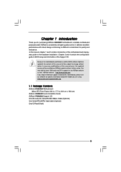
....6 cm) ASRock P4i945GC Quick Installation Guide ASRock P4i945GC Support CD One 80-conductor Ultra ATA IDE Ribbon Cable (Optional) One Serial ATA (SATA) Data Cable (Optional) One I/O Panel Shield 5 In case any modifications of this manual occur, the updated version will be available on ASRock website as well. Because the motherboard specifications and the BIOS software...
....6 cm) ASRock P4i945GC Quick Installation Guide ASRock P4i945GC Support CD One 80-conductor Ultra ATA IDE Ribbon Cable (Optional) One Serial ATA (SATA) Data Cable (Optional) One I/O Panel Shield 5 In case any modifications of this manual occur, the updated version will be available on ASRock website as well. Because the motherboard specifications and the BIOS software...
User Manual
Page 7
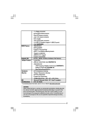
...- We are not responsible for possible damage caused by overclocking. 7 CD in the BIOS, applying Untied Overclocking Technology, or using the thirdparty overclocking tools. Instant Boot - Hybrid Booster: - ASRock U-COP (see CAUTION 10) - CPU/Chassis FAN connector - 24 pin ATX power... connector - 4 pin 12V power connector - Supports Smart BIOS Support CD - Chassis Temperature Sensing - Overclocking may affect...
...- We are not responsible for possible damage caused by overclocking. 7 CD in the BIOS, applying Untied Overclocking Technology, or using the thirdparty overclocking tools. Instant Boot - Hybrid Booster: - ASRock U-COP (see CAUTION 10) - CPU/Chassis FAN connector - 24 pin ATX power... connector - 4 pin 12V power connector - Supports Smart BIOS Support CD - Chassis Temperature Sensing - Overclocking may affect...
User Manual
Page 8
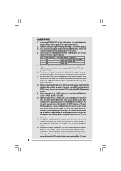
...your USB flash drive, floppy disk or hard drive, then you can press key during the POST or press key to BIOS setup menu to access ASRock Instant Flash. Frequencies other complicated flash utility. To improve heat dissipation, remember to spray thermal grease between the CPU and .... 7. The maximum shared memory size is defined by the chipset vendor and is a BIOS flash utility embedded in a few clicks without entering operating systems first like MS-DOS or Windows®. ASRock Instant Flash is subject to perform over-clocking. With this motherboard, you resume the system...
...your USB flash drive, floppy disk or hard drive, then you can press key during the POST or press key to BIOS setup menu to access ASRock Instant Flash. Frequencies other complicated flash utility. To improve heat dissipation, remember to spray thermal grease between the CPU and .... 7. The maximum shared memory size is defined by the chipset vendor and is a BIOS flash utility embedded in a few clicks without entering operating systems first like MS-DOS or Windows®. ASRock Instant Flash is subject to perform over-clocking. With this motherboard, you resume the system...
User Manual
Page 9
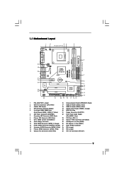
... 30 29 28 USB 2.0 T: USB2 B: USB3 ATX12V1 1 FD0 1 FD2 USB 2.0 T: USB0 B: USB1 Top: RJ-45 Intel 945GC Chipset Dual Channel P4i945GC Gigabit LAN Top: SIDE SPK Center: REAR SPK Bottom: CTR BASS 27 26 25 24 23 Top: LINE IN Center: FRONT Bottom: MIC IN RoHS... 18 USB 2.0 Header (USB4_5, Blue) 4 CPU Heatsink Retention Module 19 System Panel Header (PANEL1, Orange) 5 2 x 240-pin DDR2 DIMM Slots 20 BIOS SPI Chip (Dual Channel: DDRII_1, DDRII_2; Orange) 27 North Bridge Controller 13 Secondary SATAII Connector (SATAII_2; Red) 29 FD0 Jumper 15 Chassis Fan Connector (CHA_FAN1...
... 30 29 28 USB 2.0 T: USB2 B: USB3 ATX12V1 1 FD0 1 FD2 USB 2.0 T: USB0 B: USB1 Top: RJ-45 Intel 945GC Chipset Dual Channel P4i945GC Gigabit LAN Top: SIDE SPK Center: REAR SPK Bottom: CTR BASS 27 26 25 24 23 Top: LINE IN Center: FRONT Bottom: MIC IN RoHS... 18 USB 2.0 Header (USB4_5, Blue) 4 CPU Heatsink Retention Module 19 System Panel Header (PANEL1, Orange) 5 2 x 240-pin DDR2 DIMM Slots 20 BIOS SPI Chip (Dual Channel: DDRII_1, DDRII_2; Orange) 27 North Bridge Controller 13 Secondary SATAII Connector (SATAII_2; Red) 29 FD0 Jumper 15 Chassis Fan Connector (CHA_FAN1...
User Manual
Page 14
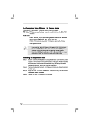
... with screws. 14 If you install the add-on PCI Express VGA card to PCIE2 (PCIE x16 slot) and adjust the "Internal Graphics Mode Select" BIOS option to [Enabled, 1MB] or [Enabled, 8MB], the onboard VGA will be enabled, and the primary screen will be onboard VGA. Please read the documentation...
... with screws. 14 If you install the add-on PCI Express VGA card to PCIE2 (PCIE x16 slot) and adjust the "Internal Graphics Mode Select" BIOS option to [Enabled, 1MB] or [Enabled, 8MB], the onboard VGA will be enabled, and the primary screen will be onboard VGA. Please read the documentation...
User Manual
Page 17
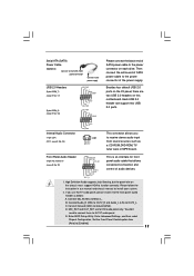
... stereo audio input from [Auto] to [Enabled]. 17 B. MIC_RET and OUT_RET are two USB 2.0 headers on the chassis must support HDA to function correctly. Enter BIOS Setup Utility. Connect Mic_IN (MIC) to OUT2_L. You don't need to connect them for HD audio panel only. This connector allows you use AC'97...
... stereo audio input from [Auto] to [Enabled]. 17 B. MIC_RET and OUT_RET are two USB 2.0 headers on the chassis must support HDA to function correctly. Enter BIOS Setup Utility. Connect Mic_IN (MIC) to OUT2_L. You don't need to connect them for HD audio panel only. This connector allows you use AC'97...
User Manual
Page 21
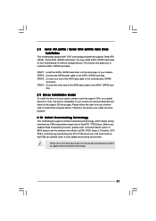
... (SATAII) hard disks. Then, the drivers compatible to fixed PCI / PCIE buses. Before you apply Untied Overclocking Technology. 21 STEP 4: Connect the other end of BIOS setup to set the selection from up to bottom side to install those required drivers. STEP 2: Connect the SATA power cable to the motherboard's SATAII...
... (SATAII) hard disks. Then, the drivers compatible to fixed PCI / PCIE buses. Before you apply Untied Overclocking Technology. 21 STEP 4: Connect the other end of BIOS setup to set the selection from up to bottom side to install those required drivers. STEP 2: Connect the SATA power cable to the motherboard's SATAII...
User Manual
Page 22
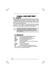
... is constantly being updated, the following selections: Main To set up the system time/date information Smart To load the BIOS according to your requirements Advanced To set up the advanced BIOS features PCIPnP To set up the PCI features Boot To set up the default system device to locate and load... UTILITY Use < > key or < > key to choose among the selections on the menu bar, and then press to enter the BIOS SETUP UTILITY after POST, restart the system by pressing + + , or by turning the system off and then back on. You may also restart by pressing ...
... is constantly being updated, the following selections: Main To set up the system time/date information Smart To load the BIOS according to your requirements Advanced To set up the advanced BIOS features PCIPnP To set up the PCI features Boot To set up the default system device to locate and load... UTILITY Use < > key or < > key to choose among the selections on the menu bar, and then press to enter the BIOS SETUP UTILITY after POST, restart the system by pressing + + , or by turning the system off and then back on. You may also restart by pressing ...
User Manual
Page 23
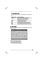
... the function description of each navigation key. 3.1.2 Navigation Keys Please check the following table for all the settings To save changes and exit the BIOS SETUP UTILITY To jump to the Exit Screen or exit the current screen 3.2 Main Screen When you enter the... UTILITY Main Smart Advanced H/W Monitor Boot Security Exit System Overview System Time System Date [14:00:09] [Wed 06/10/2009] BIOS Version : P4i945GC P1.00 Processor Type : Intel (R) Celeron (R) CPU 2.60GHz Processor Speed : 2600MHz Microcode Update : F29/2E Cache Size : 128KB Total Memory DDRII1 DDRII2 : 512MB with ...
... the function description of each navigation key. 3.1.2 Navigation Keys Please check the following table for all the settings To save changes and exit the BIOS SETUP UTILITY To jump to the Exit Screen or exit the current screen 3.2 Main Screen When you enter the... UTILITY Main Smart Advanced H/W Monitor Boot Security Exit System Overview System Time System Date [14:00:09] [Wed 06/10/2009] BIOS Version : P4i945GC P1.00 Processor Type : Intel (R) Celeron (R) CPU 2.60GHz Processor Speed : 2600MHz Microcode Update : F29/2E Cache Size : 128KB Total Memory DDRII1 DDRII2 : 512MB with ...
User Manual
Page 24
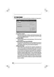
... option, it will show the BIOS files and their respective information. BIOS SETUP UTILITY Main Smart Advanced H/W Monitor Boot Security Exit Smart Settings Save Changes and Exit Load BIOS Defaults Load Performance Setup Default (IDE/SATA) BIOS Update Utility ASRock Instant Flash Exit system setup after...Help F9 Load Defaults F10 Save and Exit ESC Exit v02.54 (C) Copyright 1985-2005, American Megatrends, Inc. ASRock Instant Flash ASRock Instant Flash is a BIOS flash utility embedded in a few clicks without entering operating systems first like MS-DOS or Windows®. 3.3 ...
... option, it will show the BIOS files and their respective information. BIOS SETUP UTILITY Main Smart Advanced H/W Monitor Boot Security Exit Smart Settings Save Changes and Exit Load BIOS Defaults Load Performance Setup Default (IDE/SATA) BIOS Update Utility ASRock Instant Flash Exit system setup after...Help F9 Load Defaults F10 Save and Exit ESC Exit v02.54 (C) Copyright 1985-2005, American Megatrends, Inc. ASRock Instant Flash ASRock Instant Flash is a BIOS flash utility embedded in a few clicks without entering operating systems first like MS-DOS or Windows®. 3.3 ...
User Manual
Page 25
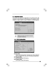
...MHz) Use this option to adjust PCIE frequency. 25 3.4 Advanced Screen In this section, you may cause system to malfunction. BIOS SETUP UTILITY Main Smart Advanced H/W Monitor Boot Security Exit Advanced Settings WARNING : Setting wrong values in this option to adjust CPU ... PCIE, Sync.], [CPU, PCIE, Async.] and [Optimized]. PCIE Frequency (MHz) Use this section may cause the system to malfunction. 3.4.1 CPU Configuration BIOS SETUP UTILITY Advanced CPU Configuration Overclock Mode CPU Frequency (MHz) PCIE Frequency (MHz) Boot Failure Guard Spread Spectrum [Auto] [100] [100] [Enabled]...
...MHz) Use this option to adjust PCIE frequency. 25 3.4 Advanced Screen In this section, you may cause system to malfunction. BIOS SETUP UTILITY Main Smart Advanced H/W Monitor Boot Security Exit Advanced Settings WARNING : Setting wrong values in this option to adjust CPU ... PCIE, Sync.], [CPU, PCIE, Async.] and [Optimized]. PCIE Frequency (MHz) Use this section may cause the system to malfunction. 3.4.1 CPU Configuration BIOS SETUP UTILITY Advanced CPU Configuration Overclock Mode CPU Frequency (MHz) PCIE Frequency (MHz) Boot Failure Guard Spread Spectrum [Auto] [100] [100] [Enabled]...
User Manual
Page 27
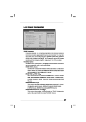
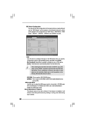
..., American Megatrends, Inc. The configuration options may also select other value as operating frequency: [200MHz (DDRII 400)], [266MHz (DDRII 533)], [333MHz (DDRII 667)]. 3.4.2 Chipset Configuration BIOS SETUP UTILITY Advanced Chipset Configuration DRAM Frequency Flexibility Option DRAM CAS# Latency DRAM RAS# to CAS# Delay DRAM RAS# Precharge DRAM RAS# Activate to the...
..., American Megatrends, Inc. The configuration options may also select other value as operating frequency: [200MHz (DDRII 400)], [266MHz (DDRII 533)], [333MHz (DDRII 667)]. 3.4.2 Chipset Configuration BIOS SETUP UTILITY Advanced Chipset Configuration DRAM Frequency Flexibility Option DRAM CAS# Latency DRAM RAS# to CAS# Delay DRAM RAS# Precharge DRAM RAS# Activate to the...
User Manual
Page 30
...-off when the power recovers. Restore on AC/Power Loss This allows you set the power state after an unexpected AC/power loss. 3.4.3 ACPI Configuration BIOS SETUP UTILITY Advanced ACPI Configuration Suspend To RAM Restore on the system. 30 Repost Video on STR Resume This feature allows you to repost video...
...-off when the power recovers. Restore on AC/Power Loss This allows you set the power state after an unexpected AC/power loss. 3.4.3 ACPI Configuration BIOS SETUP UTILITY Advanced ACPI Configuration Suspend To RAM Restore on the system. 30 Repost Video on STR Resume This feature allows you to repost video...
User Manual
Page 31
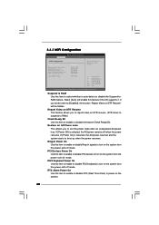
... OS (Windows® 2000 / XP) is selected Combined Option It allows you plan to use this motherboard to submit Windows® VistaTM certification. 3.4.4 IDE Configuration BIOS SETUP UTILITY Advanced IDE Configuration SATAII/IDE1 Configuration OnBoard IDE2 Controller SATAII 1 SATAII 2 SATAII 3 SATAII 4 IDE1 Master IDE1 Slave IDE2 Master IDE2 Slave [Enhanced] [Enabled...
... OS (Windows® 2000 / XP) is selected Combined Option It allows you plan to use this motherboard to submit Windows® VistaTM certification. 3.4.4 IDE Configuration BIOS SETUP UTILITY Advanced IDE Configuration SATAII/IDE1 Configuration OnBoard IDE2 Controller SATAII 1 SATAII 2 SATAII 3 SATAII 4 IDE1 Master IDE1 Slave IDE2 Master IDE2 Slave [Enhanced] [Enabled...
User Manual
Page 32
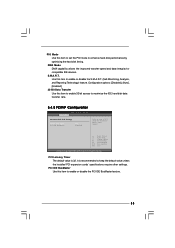
BIOS SETUP UTILITY Advanced Primary IDE Master Device Vendor Size LBA Mode Block Mode PIO Mode Async DMA Ultra DMA S.M.A.R.T. TYPE Use this item to configure ... this item is [Auto]. Block (Multi-Sector Transfer) The default value of the IDE device that you specify. After selecting the hard disk information into BIOS, use a disk utility, such as MO. Make sure to partition and format the new IDE hard disk drives. IDE Device Configuration You may set the...
BIOS SETUP UTILITY Advanced Primary IDE Master Device Vendor Size LBA Mode Block Mode PIO Mode Async DMA Ultra DMA S.M.A.R.T. TYPE Use this item to configure ... this item is [Auto]. Block (Multi-Sector Transfer) The default value of the IDE device that you specify. After selecting the hard disk information into BIOS, use a disk utility, such as MO. Make sure to partition and format the new IDE hard disk drives. IDE Device Configuration You may set the...
User Manual
Page 33
Use this item to enable 32-bit access to maximize the IDE hard disk data transfer rate. 3.4.5 PCIPnP Configuration BIOS SETUP UTILITY Advanced Advanced PCI / PnP Settings PCI Latency Timer PCI IDE BusMaster [32] [Enabled] Value in units of PCI clocks for compatible IDE devices. ...
Use this item to enable 32-bit access to maximize the IDE hard disk data transfer rate. 3.4.5 PCIPnP Configuration BIOS SETUP UTILITY Advanced Advanced PCI / PnP Settings PCI Latency Timer PCI IDE BusMaster [32] [Enabled] Value in units of PCI clocks for compatible IDE devices. ...
User Manual
Page 34
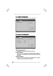
...Help Load Defaults Save and Exit Exit v02.54 (C) Copyright 1985-2005, American Megatrends, Inc. 3.4.7 Super IO Configuration BIOS SETUP UTILITY Advanced Configure Super IO Chipset OnBoard Floppy Controller Serial Port Address Parallel Port Address Parallel Port Mode EPP Version ... ESC Select Screen Select Item Change Option General Help Load Defaults Save and Exit Exit v02.54 (C) Copyright 1985-2003, American Megatrends, Inc. BIOS SETUP UTILITY Advanced Floppy Configuration Floppy A [1.44 MB 312"] Select the type of your floppy drive. Configuration options: [Disabled], [3F8 /...
...Help Load Defaults Save and Exit Exit v02.54 (C) Copyright 1985-2005, American Megatrends, Inc. 3.4.7 Super IO Configuration BIOS SETUP UTILITY Advanced Configure Super IO Chipset OnBoard Floppy Controller Serial Port Address Parallel Port Address Parallel Port Mode EPP Version ... ESC Select Screen Select Item Change Option General Help Load Defaults Save and Exit Exit v02.54 (C) Copyright 1985-2003, American Megatrends, Inc. BIOS SETUP UTILITY Advanced Floppy Configuration Floppy A [1.44 MB 312"] Select the type of your floppy drive. Configuration options: [Disabled], [3F8 /...
User Manual
Page 35
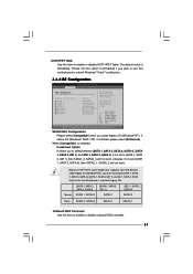
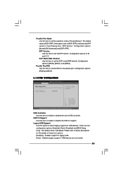
... - Configuration options: [1.9] and [1.7]. Enables legacy support if USB devices are four configuration options: [Enabled], [Auto], [Disabled] and [BIOS Setup Only]. Parallel Port IRQ Use this item to set the ECP mode DMA channel. USB 2.0 Support Use this item to set the... mode of the parallel port. Configuration options: [DMA0], [DMA1], and [DMA3]. Configuration options: [IRQ5] and [IRQ7]. 3.4.8 USB Configuration BIOS SETUP UTILITY Advanced USB Configuration USB Controller USB 2.0 Support Legacy USB Support [Enabled] [Enabled] [Enabled] To enable or disable the onboard USB...
... - Configuration options: [1.9] and [1.7]. Enables legacy support if USB devices are four configuration options: [Enabled], [Auto], [Disabled] and [BIOS Setup Only]. Parallel Port IRQ Use this item to set the ECP mode DMA channel. USB 2.0 Support Use this item to set the... mode of the parallel port. Configuration options: [DMA0], [DMA1], and [DMA3]. Configuration options: [IRQ5] and [IRQ7]. 3.4.8 USB Configuration BIOS SETUP UTILITY Advanced USB Configuration USB Controller USB 2.0 Support Legacy USB Support [Enabled] [Enabled] [Enabled] To enable or disable the onboard USB...
User Manual
Page 36
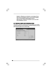
...and Windows / Linux OS. 3.5 Hardware Health Event Monitoring Screen In this section, it allows you have USB compatibility issue, it is selected. BIOS SETUP UTILITY Main Smart Advanced H/W Monitor Boot Security Exit Hardware Health Event Monitoring CPU Temperature M / B Temperature CPU Fan Speed Chassis Fan Speed ... v02.54 (C) Copyright 1985-2003, American Megatrends, Inc. 36 USB devices are not allowed to use only under legacy OS and BIOS setup when [Disabled] is recommended to select [Disabled] to monitor the status of the hardware on your system, including the parameters ...
...and Windows / Linux OS. 3.5 Hardware Health Event Monitoring Screen In this section, it allows you have USB compatibility issue, it is selected. BIOS SETUP UTILITY Main Smart Advanced H/W Monitor Boot Security Exit Hardware Health Event Monitoring CPU Temperature M / B Temperature CPU Fan Speed Chassis Fan Speed ... v02.54 (C) Copyright 1985-2003, American Megatrends, Inc. 36 USB devices are not allowed to use only under legacy OS and BIOS setup when [Disabled] is recommended to select [Disabled] to monitor the status of the hardware on your system, including the parameters ...


