
User Manual
Page 3
... Contents 4 1.2 Specifications 5 1.3 Motherboard Layout 9 1.4 ASRock I/OTM 10 2 Installation 11 2.1 Screw Holes 11 2.2 Pre-installation Precautions 11 2.3 CPU Installation 12 2.4 Installation of CPU fan and Heatsink 12 2.5 Installation of Memory Modules (DIMM 13 2.6 Expansion Slots (PCI and AGP Slots 14 2.7 Jumpers Setup 15 2.8 Connectors 16 3 BIOS Setup 18 3.1 BIOS Setup Utility 18 3.1.1 BIOS Menu Bar 18 3.1.2 Legend Bar 18 3.2 Main Menu 19 3.3 Advanced, Security, Power, Boot, and Exit Menus ..... 21 4 Software Support 22 4.1 Installing Operating System 22 4.2 Support CD...
... Contents 4 1.2 Specifications 5 1.3 Motherboard Layout 9 1.4 ASRock I/OTM 10 2 Installation 11 2.1 Screw Holes 11 2.2 Pre-installation Precautions 11 2.3 CPU Installation 12 2.4 Installation of CPU fan and Heatsink 12 2.5 Installation of Memory Modules (DIMM 13 2.6 Expansion Slots (PCI and AGP Slots 14 2.7 Jumpers Setup 15 2.8 Connectors 16 3 BIOS Setup 18 3.1 BIOS Setup Utility 18 3.1.1 BIOS Menu Bar 18 3.1.2 Legend Bar 18 3.2 Main Menu 19 3.3 Advanced, Security, Power, Boot, and Exit Menus ..... 21 4 Software Support 22 4.1 Installing Operating System 22 4.2 Support CD...

User Manual
Page 4
... IDE Ribbon Cable One Ribbon Cable for purchasing ASRock P4i45E motherboard, a reliable motherboard produced under ASRock's consistently stringent quality control. Chapter 3 and 4 contain basic BIOS setup and Support CD information. Chapter 1 and 2 of this manual occur, the updated version will be available on ASRock website without notice. You may find the latest memory and CPU support lists on page 23 offers more advanced BIOS setup information. Because the motherboard specifications and the BIOS software might be updated...
... IDE Ribbon Cable One Ribbon Cable for purchasing ASRock P4i45E motherboard, a reliable motherboard produced under ASRock's consistently stringent quality control. Chapter 3 and 4 contain basic BIOS setup and Support CD information. Chapter 1 and 2 of this manual occur, the updated version will be available on ASRock website without notice. You may find the latest memory and CPU support lists on page 23 offers more advanced BIOS setup information. Because the motherboard specifications and the BIOS software might be updated...

User Manual
Page 5
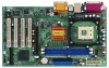
... DMA Mode 5; Supports up to 4 IDE devices Floppy Port: Supports up events; ACPI 1.1 compliance wake up to protect CPU life (ASRock U-COP)(see CAUTION 2); Voltage monitoring: +12V, +5V, +3V, Vcore PCI slots: 4 PCI slots with PCI Specification 2.2 AGP slot: 1 AGP slot, supports 1.5V, 4X AGP card (see CAUTION 4) USB 2.0: 4 default USB 2.0 ports and one extra set of header for two ASRock I/OTM: additional USB 2.0 ports upgrade (see CAUTION 6) OS: Microsoft® Windows® 98 SE / ME / 2000 / XP compliant 5 SMBIOS 2.3.1 support; CPU frequency stepless control (only...
... DMA Mode 5; Supports up to 4 IDE devices Floppy Port: Supports up events; ACPI 1.1 compliance wake up to protect CPU life (ASRock U-COP)(see CAUTION 2); Voltage monitoring: +12V, +5V, +3V, Vcore PCI slots: 4 PCI slots with PCI Specification 2.2 AGP slot: 1 AGP slot, supports 1.5V, 4X AGP card (see CAUTION 4) USB 2.0: 4 default USB 2.0 ports and one extra set of header for two ASRock I/OTM: additional USB 2.0 ports upgrade (see CAUTION 6) OS: Microsoft® Windows® 98 SE / ME / 2000 / XP compliant 5 SMBIOS 2.3.1 support; CPU frequency stepless control (only...

User Manual
Page 6
... NOTE on P4i45E motherboard! Do NOT plug a 3.3V AGP card in the AGP slot on pages 7-8 for USB 2.0 works fine under Microsoft® Windows® 98 / ME. Frequencies other clocks, such as PCI clock, AGP clock, and Memory clock will automatically shutdown. About the setting of the system or damage the CPU and the motherboard. 6 It may be overclocked proportionally. Please refer to perform over -clocking mode). When the CPU frequency of P4i45E is...
... NOTE on P4i45E motherboard! Do NOT plug a 3.3V AGP card in the AGP slot on pages 7-8 for USB 2.0 works fine under Microsoft® Windows® 98 / ME. Frequencies other clocks, such as PCI clock, AGP clock, and Memory clock will automatically shutdown. About the setting of the system or damage the CPU and the motherboard. 6 It may be overclocked proportionally. Please refer to perform over -clocking mode). When the CPU frequency of P4i45E is...

User Manual
Page 11
Whenever you install motherboard components or change any component, place it . Failure to do so may cause severe damage to static electricity, NEVER place your chassis to the chassis. Chapter 2 Installation P4i45E is detached from the wall socket before installing or removing the motherboard. Unplug the power cord from the power supply. Hold components by circles to secure the motherboard to ensure that the power is switched off or...
Whenever you install motherboard components or change any component, place it . Failure to do so may cause severe damage to static electricity, NEVER place your chassis to the chassis. Chapter 2 Installation P4i45E is detached from the wall socket before installing or removing the motherboard. Unplug the power cord from the power supply. Hold components by circles to secure the motherboard to ensure that the power is switched off or...

User Manual
Page 16
.../100 cable Note: If you 4 default USB 2.0 ports on this motherboard, please set the IDE device as "Master". USB 2.0 Header (9-pin USB45) (see p.9 item 17) IRTX +5V DUMMY 1 GND IRRX This connector supports an optional wireless transmitting and receiving infrared module. 16 Connector FDD connector (33-pin FLOPPY1) (see p.9 item 7) PIN1 IDE1 PIN1 IDE2 connect the blue end connect the black end to the motherboard to support 2 additional USB 2.0 ports. Infrared module connector (5-pin IR1...
.../100 cable Note: If you 4 default USB 2.0 ports on this motherboard, please set the IDE device as "Master". USB 2.0 Header (9-pin USB45) (see p.9 item 17) IRTX +5V DUMMY 1 GND IRRX This connector supports an optional wireless transmitting and receiving infrared module. 16 Connector FDD connector (33-pin FLOPPY1) (see p.9 item 7) PIN1 IDE1 PIN1 IDE2 connect the blue end connect the black end to the motherboard to support 2 additional USB 2.0 ports. Infrared module connector (5-pin IR1...

User Manual
Page 17
... a CD-ROM, DVD-ROM, TV tuner card, or MPEG card. O U T- R MIC-POWER MIC PLED+ PLEDPWRBTN# GND 1 DUMMY RESET# GND HDLEDHDLED+ This is an interface for front panel audio cable that allows convenient connection and control of audio devices. ATX power connector (20-pin ATXPWR1) (see p.9 item 15) CPU_FAN_SPEED +12V GND Connect the fan cable to the connector matching the black wire to the ground pin. Chassis fan connector (3-pin CHA_FAN1) (see p.9 item 6) Connect an ATX power supply to the connector. 17 Internal audio connectors (4-pin CD1, 4-pin AUX1...
... a CD-ROM, DVD-ROM, TV tuner card, or MPEG card. O U T- R MIC-POWER MIC PLED+ PLEDPWRBTN# GND 1 DUMMY RESET# GND HDLEDHDLED+ This is an interface for front panel audio cable that allows convenient connection and control of audio devices. ATX power connector (20-pin ATXPWR1) (see p.9 item 15) CPU_FAN_SPEED +12V GND Connect the fan cable to the connector matching the black wire to the ground pin. Chassis fan connector (3-pin CHA_FAN1) (see p.9 item 6) Connect an ATX power supply to the connector. 17 Internal audio connectors (4-pin CD1, 4-pin AUX1...

User Manual
Page 18
... BIOS Setup Utility, otherwise, POST continues with their corresponding functions. 18 Press during the Power-On-Self-Test (POST) to be user-friendly. The BIOS Setup Utility is a chance for reference purpose only, and may not exactly match what you to run the BIOS Setup. The BIOS FWH chip on . When you start up the security features POWER Configures Power Management features BOOT Configures the default system device that is used to configure your screen. 3.1.1 BIOS Menu...
... BIOS Setup Utility, otherwise, POST continues with their corresponding functions. 18 Press during the Power-On-Self-Test (POST) to be user-friendly. The BIOS Setup Utility is a chance for reference purpose only, and may not exactly match what you to run the BIOS Setup. The BIOS FWH chip on . When you start up the security features POWER Configures Power Management features BOOT Configures the default system device that is used to configure your screen. 3.1.1 BIOS Menu...

User Manual
Page 19
... set the type of floppy drives installed. IDE Devices Use this to configure IDE devices. 19 VERSION 3.31a Security Power Boot Exit Oct 27 2003 Mon 16:07:40 [ Setup Help ] Month: Jan - Dec Day: 01 - 31 Year: 1980 - 2099 P4I45E BIOS P2.10 Pentium (R) 4 CPU 2400 MHz 512 KB F24 / 18 256 MB 256 MB / 133 MHz (DDR266) None F1:Help Esc:Exit :Select Item :Select Menu +/-:Change Values Enter...
... set the type of floppy drives installed. IDE Devices Use this to configure IDE devices. 19 VERSION 3.31a Security Power Boot Exit Oct 27 2003 Mon 16:07:40 [ Setup Help ] Month: Jan - Dec Day: 01 - 31 Year: 1980 - 2099 P4I45E BIOS P2.10 Pentium (R) 4 CPU 2400 MHz 512 KB F24 / 18 256 MB 256 MB / 133 MHz (DDR266) None F1:Help Esc:Exit :Select Item :Select Menu +/-:Change Values Enter...

User Manual
Page 20
... hard disk. After entering the hard disk information into BIOS, use a disk utility, such as FDISK, to get into the sub-menu. TYPE To set the type of the IDE device, first, please select "IDE Devices" on Main menu and press to partition and format new IDE hard disk drives. After making your selections on this sub-menu. VERSION 3.31a Primary IDE Master: [ Setup Help ] Type Cylinders Heads Write Precompensation Sectors Maximum Capacity LBA Mode Block Mode Fast Programmed I/O Modes 32 Bit...
... hard disk. After entering the hard disk information into BIOS, use a disk utility, such as FDISK, to get into the sub-menu. TYPE To set the type of the IDE device, first, please select "IDE Devices" on Main menu and press to partition and format new IDE hard disk drives. After making your selections on this sub-menu. VERSION 3.31a Primary IDE Master: [ Setup Help ] Type Cylinders Heads Write Precompensation Sectors Maximum Capacity LBA Mode Block Mode Fast Programmed I/O Modes 32 Bit...
User Manual
Page 21
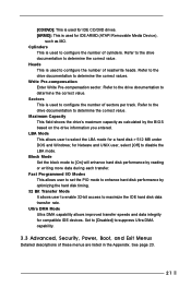
.... Fast Programmed I/O Modes This allows user to set the PIO mode to configure the number of these menus are listed in the Appendix. [CD/DVD]: This is used for IDE CD/DVD drives. [ARMD]: This is used for IDE ARMD (ATAPI Removable Media Device), such as calculated by the BIOS based on the drive information you entered. See page 23. 21 Sectors This is used to enhance hard disk performance by...
.... Fast Programmed I/O Modes This allows user to set the PIO mode to configure the number of these menus are listed in the Appendix. [CD/DVD]: This is used for IDE CD/DVD drives. [ARMD]: This is used for IDE ARMD (ATAPI Removable Media Device), such as calculated by the BIOS based on the drive information you entered. See page 23. 21 Sectors This is used to enhance hard disk performance by...

User Manual
Page 22
...® Windows® operating systems: 98 SE / ME / 2000 / XP. Click on the file ASSETUP.EXE from the BIN folder in your CD-ROM drive. Refer to activate the devices. 4.2.3 Utilities Menu The Utilities Menu shows the applications software that will enhance the motherboard features. 4.2.1 Running The Support CD To begin using the support CD, insert the CD into your computer. Install the necessary drivers to...
...® Windows® operating systems: 98 SE / ME / 2000 / XP. Click on the file ASSETUP.EXE from the BIN folder in your CD-ROM drive. Refer to activate the devices. 4.2.3 Utilities Menu The Utilities Menu shows the applications software that will enhance the motherboard features. 4.2.1 Running The Support CD To begin using the support CD, insert the CD into your computer. Install the necessary drivers to...

User Manual
Page 23
... [Auto] if using Microsoft® Windows® XP, or Linux kernel version 2.4.18 or higher. DRAM Frequency: If set to [Auto], the motherboard will introduce you the following BIOS Setup menus: "Advanced," "Security," "Power," "Boot," and "Exit." 1. Set to enable or disable the feature of spread spectrum. CPU Ratio Selection: CPU Ratio is determined by the installed processor. Chipset Configuration Resource Configuration Peripheral Configuration System Hardware Monitor F1:Help Esc:Exit :Select Item :Select Menu +/-:Change Values Enter...
... [Auto] if using Microsoft® Windows® XP, or Linux kernel version 2.4.18 or higher. DRAM Frequency: If set to [Auto], the motherboard will introduce you the following BIOS Setup menus: "Advanced," "Security," "Power," "Boot," and "Exit." 1. Set to enable or disable the feature of spread spectrum. CPU Ratio Selection: CPU Ratio is determined by the installed processor. Chipset Configuration Resource Configuration Peripheral Configuration System Hardware Monitor F1:Help Esc:Exit :Select Item :Select Menu +/-:Change Values Enter...

User Manual
Page 24
...DRAM Write Throttling: Select [Enabled] will enable P4 thermal control circuit to enable or disable the use of mapped memory for graphics memory. VERSION 3.31a Chipset Configuration [ Setup Help ] AGP Aperture Size ICH Delayed Transaction USB Controller USB Device Legacy Support CPU Thermal Throttling DRAM Write Throttling SDRAM CAS Latency ******** DRAM Timing ******** Configure SDRAM Timing by SPD SDRAM RAS# Precharge SDRAM RAS# to CAS# Delay 64MB Disabled Enabled Disabled Disabled Disabled Auto Disabled 3 Clocks 3 Clocks to emulate legacy I/O devices such as mouse, keyboard...
...DRAM Write Throttling: Select [Enabled] will enable P4 thermal control circuit to enable or disable the use of mapped memory for graphics memory. VERSION 3.31a Chipset Configuration [ Setup Help ] AGP Aperture Size ICH Delayed Transaction USB Controller USB Device Legacy Support CPU Thermal Throttling DRAM Write Throttling SDRAM CAS Latency ******** DRAM Timing ******** Configure SDRAM Timing by SPD SDRAM RAS# Precharge SDRAM RAS# to CAS# Delay 64MB Disabled Enabled Disabled Disabled Disabled Auto Disabled 3 Clocks 3 Clocks to emulate legacy I/O devices such as mouse, keyboard...
User Manual
Page 26
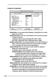
...: Use this option to enable or disable the floppy drive controller. Peripheral Configuration: Advanced AMIBIOS SETUP UTILITY - VERSION 3.31a Peripheral Configuration [ Setup Help ] OnBoard FDC OnBoard Serial Port OnBoard Infrared Port OnBoard Parallel Port Parallel Port Mode EPP Version Parallel Port IRQ Parallel Port DMA Channel OnBoard Midi Port Midi IRQ Select OnBoard Game Port OnBoard IDE OnBoard LAN OnBoard AC' 97 Audio Auto Auto Disabled Auto ECP + EPP 1.9 Auto Auto Disabled 5 200H Both Enabled Auto to select Parallel Port address or disable the on -board Midi Port or...
...: Use this option to enable or disable the floppy drive controller. Peripheral Configuration: Advanced AMIBIOS SETUP UTILITY - VERSION 3.31a Peripheral Configuration [ Setup Help ] OnBoard FDC OnBoard Serial Port OnBoard Infrared Port OnBoard Parallel Port Parallel Port Mode EPP Version Parallel Port IRQ Parallel Port DMA Channel OnBoard Midi Port Midi IRQ Select OnBoard Game Port OnBoard IDE OnBoard LAN OnBoard AC' 97 Audio Auto Auto Disabled Auto ECP + EPP 1.9 Auto Auto Disabled 5 200H Both Enabled Auto to select Parallel Port address or disable the on -board Midi Port or...

User Manual
Page 27
... Hardware Monitor [ Setup Help ] CPU Temperature M/B Temperature CPU Fan Speed Chassis Fan Speed Vcore + 3.30V + 5.00V +12.00V 39 C / 102 F 31 C / 87 F 4197 RPM 0 RPM 1.504 V 3.280 V 4.865 V 12.045 V F1:Help Esc:Previous Menu :Select Item +/-:Change Values Enter:Select Sub-Menu F9:Setup Defaults F10:Save & Exit 27 OnBoard LAN: This allows you to enable or disable the on -board AC'97 Audio feature. Advanced AMIBIOS SETUP UTILITY - OnBoard AC'97 Audio: Select [Enabled], [Auto] or [Disabled] for CPU temperature, Motherboard temperature, CPU fan speed...
... Hardware Monitor [ Setup Help ] CPU Temperature M/B Temperature CPU Fan Speed Chassis Fan Speed Vcore + 3.30V + 5.00V +12.00V 39 C / 102 F 31 C / 87 F 4197 RPM 0 RPM 1.504 V 3.280 V 4.865 V 12.045 V F1:Help Esc:Previous Menu :Select Item +/-:Change Values Enter:Select Sub-Menu F9:Setup Defaults F10:Save & Exit 27 OnBoard LAN: This allows you to enable or disable the on -board AC'97 Audio feature. Advanced AMIBIOS SETUP UTILITY - OnBoard AC'97 Audio: Select [Enabled], [Auto] or [Disabled] for CPU temperature, Motherboard temperature, CPU fan speed...

User Manual
Page 28
... +/-:Change Values Enter:Select Sub-Menu F9:Setup Defaults F10:Save & Exit Supervisor Password Is: This field shows the status of the User Password. [Clear]: No password has been set. [Set]: User password has been set User Password. Configuration options: [Setup], [Always]. Valid password can be a 1 to set . Set Supervisor Password: Press to 6 alphanumeric characters combination. If [Setup] option is selected, the "Password Check" is performed before BIOS setup. Security Setup Menu Main Advanced AMIBIOS SETUP UTILITY - Set User Password: Press to enable or disable...
... +/-:Change Values Enter:Select Sub-Menu F9:Setup Defaults F10:Save & Exit Supervisor Password Is: This field shows the status of the User Password. [Clear]: No password has been set. [Set]: User password has been set User Password. Configuration options: [Setup], [Always]. Valid password can be a 1 to set . Set Supervisor Password: Press to 6 alphanumeric characters combination. If [Setup] option is selected, the "Password Check" is performed before BIOS setup. Security Setup Menu Main Advanced AMIBIOS SETUP UTILITY - Set User Password: Press to enable or disable...

User Manual
Page 29
.... RTC Alarm Power On: Use this feature by selecting [Disabled]. If [Power On] is recommended to set the power state after an unexpected AC/power loss. If [Enable] is selected, the AC/power remains off mode. 3. VERSION 3.31a Security Power Boot Exit Suspend To RAM Repost Video on S3 Resume Restore on the system. Power Setup Menu Main Advanced AMIBIOS SETUP UTILITY - Select [Auto] will enable this feature under Microsoft® Windows® 98...
.... RTC Alarm Power On: Use this feature by selecting [Disabled]. If [Power On] is recommended to set the power state after an unexpected AC/power loss. If [Enable] is selected, the AC/power remains off mode. 3. VERSION 3.31a Security Power Boot Exit Suspend To RAM Repost Video on S3 Resume Restore on the system. Power Setup Menu Main Advanced AMIBIOS SETUP UTILITY - Select [Auto] will enable this feature under Microsoft® Windows® 98...

User Manual
Page 30
...] to enable boot-up . Boot From Network: Use this mode will speed up the boot-up routine by skipping memory retestings. Boot Setup Menu Main Advanced AMIBIOS SETUP UTILITY - VERSION 3.31a Security Power Boot Exit Quick Boot Mode Boot Up Num-Lock Boot To OS/2 Boot From Network Enabled On No Disabled [ Setup Help ] to enable or disable "boot from network" feature. 4. Boot Up Num-Lock: Select [On] to activate the Numeric Lock function automatically after boot-up to set the boot device priority. 30 Boot Device Priority...
...] to enable boot-up . Boot From Network: Use this mode will speed up the boot-up routine by skipping memory retestings. Boot Setup Menu Main Advanced AMIBIOS SETUP UTILITY - VERSION 3.31a Security Power Boot Exit Quick Boot Mode Boot Up Num-Lock Boot To OS/2 Boot From Network Enabled On No Disabled [ Setup Help ] to enable or disable "boot from network" feature. 4. Boot Up Num-Lock: Select [On] to activate the Numeric Lock function automatically after boot-up to set the boot device priority. 30 Boot Device Priority...

User Manual
Page 31
... settings and exit the BIOS SETUP Utility. VERSION 3.31a Security Power Boot Exit Exit Saving Changes Exit Discarding Changes Load Default Settings Discard Changes [ Enter ] [ Enter ] [ Enter ] [ Enter ] [ Setup Help ] Exits and saves the changes in CMOS RAM. F1:Help Esc:Exit :Select Item :Select Menu +/-:Change Values Enter:Select Sub-Menu F9:Setup Defaults F10:Save & Exit Exit Saving Changes: After you press , it will appear. Discard Changes: After you enter the submenu, the message "Load default settings" will appear. 5. Load Default Settings: After you enter...
... settings and exit the BIOS SETUP Utility. VERSION 3.31a Security Power Boot Exit Exit Saving Changes Exit Discarding Changes Load Default Settings Discard Changes [ Enter ] [ Enter ] [ Enter ] [ Enter ] [ Setup Help ] Exits and saves the changes in CMOS RAM. F1:Help Esc:Exit :Select Item :Select Menu +/-:Change Values Enter:Select Sub-Menu F9:Setup Defaults F10:Save & Exit Exit Saving Changes: After you press , it will appear. Discard Changes: After you enter the submenu, the message "Load default settings" will appear. 5. Load Default Settings: After you enter...


