User Manual
Page 3
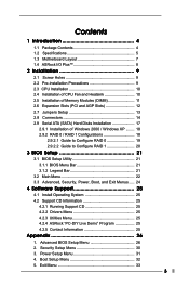
...5. Advanced BIOS Setup Menu 26 2. Security Setup Menu 30 3. Contents 1 Introduction 4 1.1 Package Contents 4 1.2 Specifications 5 1.3 Motherboard Layout 7 1.4 ASRock I/O PlusTM 8 2 Installation 9 2.1 Screw Holes 9 2.2 Pre-installation Precautions 9 2.3 CPU Installation 10 2.4 Installation of CPU Fan and Heatsink 10 ... Memory Modules (DIMM 11 2.6 Expansion Slots (PCI and AGP Slots 12 2.7 Jumpers Setup 13 2.8 Connectors 14 2.9 Serial ATA (SATA) Hard Disks Installation 17 2.9.1 Installation of Windows 2000 / Windows XP ........ 18 2.9.2 RAID 0 / RAID 1 Configurations 18 2.9.2.1 ...
...5. Advanced BIOS Setup Menu 26 2. Security Setup Menu 30 3. Contents 1 Introduction 4 1.1 Package Contents 4 1.2 Specifications 5 1.3 Motherboard Layout 7 1.4 ASRock I/O PlusTM 8 2 Installation 9 2.1 Screw Holes 9 2.2 Pre-installation Precautions 9 2.3 CPU Installation 10 2.4 Installation of CPU Fan and Heatsink 10 ... Memory Modules (DIMM 11 2.6 Expansion Slots (PCI and AGP Slots 12 2.7 Jumpers Setup 13 2.8 Connectors 14 2.9 Serial ATA (SATA) Hard Disks Installation 17 2.9.1 Installation of Windows 2000 / Windows XP ........ 18 2.9.2 RAID 0 / RAID 1 Configurations 18 2.9.2.1 ...
User Manual
Page 4
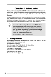
...to quality and endurance. Chapter 1 Introduction Thank you for a 3.5-in Floppy Drive One Serial ATA (SATA) Cables One Serial ATA (SATA) HDD Power Cable (Optional) One ASRock I/O PlusTM Shield One Game Port Bracket (Optional) 4 Because the motherboard specifications and the BIOS software ...3 and 4 contain basic BIOS setup and support CD information. ASRock website http://www.asrock.com 1.1 Package Contents ASRock P4VT8+ Motherboard (ATX Form Factor: 12.0-in x 7.5-in, 30.5 cm x 19.1 cm) ASRock P4VT8+ Quick Installation Guide ASRock P4VT8+ Support CD One 80-conductor Ultra ATA 66/100/133 IDE...
...to quality and endurance. Chapter 1 Introduction Thank you for a 3.5-in Floppy Drive One Serial ATA (SATA) Cables One Serial ATA (SATA) HDD Power Cable (Optional) One ASRock I/O PlusTM Shield One Game Port Bracket (Optional) 4 Because the motherboard specifications and the BIOS software ...3 and 4 contain basic BIOS setup and support CD information. ASRock website http://www.asrock.com 1.1 Package Contents ASRock P4VT8+ Motherboard (ATX Form Factor: 12.0-in x 7.5-in, 30.5 cm x 19.1 cm) ASRock P4VT8+ Quick Installation Guide ASRock P4VT8+ Support CD One 80-conductor Ultra ATA 66/100/133 IDE...
User Manual
Page 5
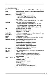
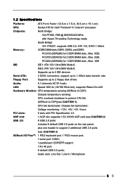
...ASRock U-COP)(see CAUTION 3) ASRock I/O PlusTM: 1 PS/2 keyboard port, 1 PS/2 mouse port; 1 serial port: COM1; 1 parallel port: ECP/EPP support; 1 RJ 45 port; 6 default USB 2.0 ports; Voltage monitoring: +12V, +5V, +3V, Vcore PCI slots: 5 slots with Hyper-Threading Technology ready South Bridge: VIA VT8237, supports USB 2.0, ATA 133, SATA...5.1 channels AC'97 Audio LAN: Speed: 802.3u (10/100 Ethernet), supports Wake-On-LAN Hardware Monitor: CPU temperature sensing (ASRock U-COP); PC2700 (DDR333) for 1 DDR DIMM slots , Max. 1GB IDE: IDE1: ATA 133 / Ultra DMA Mode 6; PC3200...
...ASRock U-COP)(see CAUTION 3) ASRock I/O PlusTM: 1 PS/2 keyboard port, 1 PS/2 mouse port; 1 serial port: COM1; 1 parallel port: ECP/EPP support; 1 RJ 45 port; 6 default USB 2.0 ports; Voltage monitoring: +12V, +5V, +3V, Vcore PCI slots: 5 slots with Hyper-Threading Technology ready South Bridge: VIA VT8237, supports USB 2.0, ATA 133, SATA...5.1 channels AC'97 Audio LAN: Speed: 802.3u (10/100 Ethernet), supports Wake-On-LAN Hardware Monitor: CPU temperature sensing (ASRock U-COP); PC2700 (DDR333) for 1 DDR DIMM slots , Max. 1GB IDE: IDE1: ATA 133 / Ultra DMA Mode 6; PC3200...
User Manual
Page 14
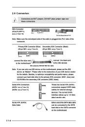
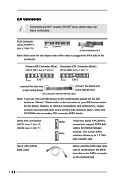
.... Serial ATA Connectors (SATA1: see p.7 item 12) (SATA2: see p.7 item 11) SATA2 SATA1 These two Serial ATA (SATA) connectors support SATA data cables for the details. The current SATA interface allows up to the secondary IDE connector (IDE2, black). FDD Connector (33-pin FLOPPY1) (see p.7 item 7) PIN1 ...) (39-pin IDE1, see p.7 item 8) (39-pin IDE2, see p.7 item 15) Pin1 FLOPPY1 the red-striped side to the SATA hard disk or the SATA connector on this motherboard, please set the IDE device as "Master". 2.8 Connectors Connectors are NOT jumpers. DO NOT place jumper caps over ...
.... Serial ATA Connectors (SATA1: see p.7 item 12) (SATA2: see p.7 item 11) SATA2 SATA1 These two Serial ATA (SATA) connectors support SATA data cables for the details. The current SATA interface allows up to the secondary IDE connector (IDE2, black). FDD Connector (33-pin FLOPPY1) (see p.7 item 7) PIN1 ...) (39-pin IDE1, see p.7 item 8) (39-pin IDE2, see p.7 item 15) Pin1 FLOPPY1 the red-striped side to the SATA hard disk or the SATA connector on this motherboard, please set the IDE device as "Master". 2.8 Connectors Connectors are NOT jumpers. DO NOT place jumper caps over ...
User Manual
Page 15
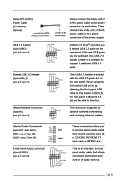
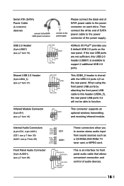
... 2.0 ports 4,5 on the rear panel. Front Panel Audio Connector (9-pin AUDIO1) (see p.7 item 19) USB_PWR P-7 P+7 GND DUMMY 1 GND P+6 P-6 USB_PWR ASRock I/O PlusTM provides you to receive stereo audio input from sound sources such as a CD-ROM, DVD-ROM, TV tuner card, or MPEG card. USB 2.0 Header...p.7 item 18) IRTX +5V DUMMY 1 GND IRRX This connector supports an optional wireless transmitting and receiving infrared module. O U T- Serial ATA (SATA) Power Cable (4-conductor) (Optional) connect to the SATA HDD power connector connect to the power supply Please connect the black end of...
... 2.0 ports 4,5 on the rear panel. Front Panel Audio Connector (9-pin AUDIO1) (see p.7 item 19) USB_PWR P-7 P+7 GND DUMMY 1 GND P+6 P-6 USB_PWR ASRock I/O PlusTM provides you to receive stereo audio input from sound sources such as a CD-ROM, DVD-ROM, TV tuner card, or MPEG card. USB 2.0 Header...p.7 item 18) IRTX +5V DUMMY 1 GND IRRX This connector supports an optional wireless transmitting and receiving infrared module. O U T- Serial ATA (SATA) Power Cable (4-conductor) (Optional) connect to the SATA HDD power connector connect to the power supply Please connect the black end of...
User Manual
Page 17
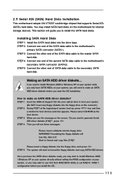
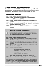
... into the floppy drive, and press . STEP 4: Connect one end of the SATA data cable to make an SATA HDD driver diskette? STEP 1: Insert the ASRock Support CD into your optical drive to the motherboard's primary SATA connector (SATA1). Once you have SATA HDDs on your system, or you may start to install Windows 2000...
... into the floppy drive, and press . STEP 4: Connect one end of the SATA data cable to make an SATA HDD driver diskette? STEP 1: Insert the ASRock Support CD into your optical drive to the motherboard's primary SATA connector (SATA1). Once you have SATA HDDs on your system, or you may start to install Windows 2000...
User Manual
Page 18
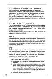
... must be the base storage size. RAID 1 RAID 1 is called data striping that integrates RAID controller supporting RAID 0 and RAID 1 with two independent Serial ATA (SATA) channels. Please use two new drives if you need to a second drive. For optimal performance, please install identical drives of your hard disks. 18 If...
... must be the base storage size. RAID 1 RAID 1 is called data striping that integrates RAID controller supporting RAID 0 and RAID 1 with two independent Serial ATA (SATA) channels. Please use two new drives if you need to a second drive. For optimal performance, please install identical drives of your hard disks. 18 If...
User Manual
Page 20
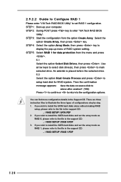
... press key. You can find more configuration details in the support CD: .. \ RAID SETUP \ RAID 1.PDF 20 If you wish to install the SATA hard disks alone without making RAID setup, please refer to mark selected drive. STEP 1: Boot-up menu of configurations step by step. 1. STEP 4: ... data protection from the option Create Array. There are three instruction files to display the pop-up your computer. If you wish to install the SATA hard disks and set RAID 1 configuration. STEP 3: Start the configuration from the menu and press . 5.1 Select the option Select Disk Drives, then ...
... press key. You can find more configuration details in the support CD: .. \ RAID SETUP \ RAID 1.PDF 20 If you wish to install the SATA hard disks alone without making RAID setup, please refer to mark selected drive. STEP 1: Boot-up menu of configurations step by step. 1. STEP 4: ... data protection from the option Create Array. There are three instruction files to display the pop-up your computer. If you wish to install the SATA hard disks and set RAID 1 configuration. STEP 3: Start the configuration from the menu and press . 5.1 Select the option Select Disk Drives, then ...
User Manual
Page 3
... 10 2.5 Installation of Memory Modules (DIMM 11 2.6 Expansion Slots (PCI and AGP Slots 12 2.7 Jumpers Setup 13 2.8 Connectors 14 2.9 Serial ATA (SATA) Hard Disks Installation 17 2.9.1 Installation of Windows 2000 / Windows XP ........ 18 2.9.2 RAID 0 / RAID 1 Configurations 18 2.9.2.1 Guide to Configure RAID... Install Operating System 25 4.2 Support CD Information 25 4.2.1 Running Support CD 25 4.2.2 Drivers Menu 25 4.2.3 Utilities Menu 25 4.2.4 ASRock "PC-DIY Live Demo" Program 25 4.2.5 Contact Information 25 Appendix 26 1. Boot Setup Menu 32 5. Power Setup Menu 31 4. Security Setup ...
... 10 2.5 Installation of Memory Modules (DIMM 11 2.6 Expansion Slots (PCI and AGP Slots 12 2.7 Jumpers Setup 13 2.8 Connectors 14 2.9 Serial ATA (SATA) Hard Disks Installation 17 2.9.1 Installation of Windows 2000 / Windows XP ........ 18 2.9.2 RAID 0 / RAID 1 Configurations 18 2.9.2.1 Guide to Configure RAID... Install Operating System 25 4.2 Support CD Information 25 4.2.1 Running Support CD 25 4.2.2 Drivers Menu 25 4.2.3 Utilities Menu 25 4.2.4 ASRock "PC-DIY Live Demo" Program 25 4.2.5 Contact Information 25 Appendix 26 1. Boot Setup Menu 32 5. Power Setup Menu 31 4. Security Setup ...
User Manual
Page 4
... contain introduction of this manual will be subject to quality and endurance. ASRock website http://www.asrock.com 1.1 Package Contents ASRock P4VT8 Motherboard (ATX Form Factor: 12.0-in x 7.5-in Floppy Drive Two Serial ATA (SATA) Cables One Serial ATA (SATA) HDD Power Cable (Optional) One ASRock I/O PlusTM Shield One Game Port Bracket (Optional) 4 Chapter 3 and 4 contain basic...
... contain introduction of this manual will be subject to quality and endurance. ASRock website http://www.asrock.com 1.1 Package Contents ASRock P4VT8 Motherboard (ATX Form Factor: 12.0-in x 7.5-in Floppy Drive Two Serial ATA (SATA) Cables One Serial ATA (SATA) HDD Power Cable (Optional) One ASRock I/O PlusTM Shield One Game Port Bracket (Optional) 4 Chapter 3 and 4 contain basic...
User Manual
Page 5
...for 2 DDR DIMM slots , Max. 2GB; Supports up to 4 IDE devices Serial ATA: 2 SATA connectors, support up to 1.5Gb/s data transfer rate Floppy Port: Supports up to protect CPU life (ASRock U-COP)(see CAUTION 3) ASRock I/O PlusTM: 1 PS/2 keyboard port, 1 PS/2 mouse port; 1 serial port: COM1; ...drives Audio: 5.1 channels AC'97 Audio LAN: Speed: 802.3u (10/100 Ethernet), supports Wake-On-LAN Hardware Monitor: CPU temperature sensing (ASRock U-COP); CPU fan tachometer; Voltage monitoring: +12V, +5V, +3V, Vcore PCI slots: 5 slots with Hyper-Threading Technology ready South ...
...for 2 DDR DIMM slots , Max. 2GB; Supports up to 4 IDE devices Serial ATA: 2 SATA connectors, support up to 1.5Gb/s data transfer rate Floppy Port: Supports up to protect CPU life (ASRock U-COP)(see CAUTION 3) ASRock I/O PlusTM: 1 PS/2 keyboard port, 1 PS/2 mouse port; 1 serial port: COM1; ...drives Audio: 5.1 channels AC'97 Audio LAN: Speed: 802.3u (10/100 Ethernet), supports Wake-On-LAN Hardware Monitor: CPU temperature sensing (ASRock U-COP); CPU fan tachometer; Voltage monitoring: +12V, +5V, +3V, Vcore PCI slots: 5 slots with Hyper-Threading Technology ready South ...
User Manual
Page 14
...striped side to optimize compatibility and performance, please connect your IDE device vendor for internal storage devices. Serial ATA (SATA) Data Cable Either end of the SATA data cable can be connected to 1.5 Gb/s data transfer rate. DO NOT place jumper caps over these connectors. ...(SATA2: see p.7 item 11) SATA2 SATA1 These two Serial ATA (SATA) connectors support SATA data cables for the details. 2.8 Connectors Connectors are NOT jumpers. The current SATA interface allows up to the SATA hard disk or the SATA connector on this motherboard, please set the IDE device as "Master". ...
...striped side to optimize compatibility and performance, please connect your IDE device vendor for internal storage devices. Serial ATA (SATA) Data Cable Either end of the SATA data cable can be connected to 1.5 Gb/s data transfer rate. DO NOT place jumper caps over these connectors. ...(SATA2: see p.7 item 11) SATA2 SATA1 These two Serial ATA (SATA) connectors support SATA data cables for the details. 2.8 Connectors Connectors are NOT jumpers. The current SATA interface allows up to the SATA hard disk or the SATA connector on this motherboard, please set the IDE device as "Master". ...
User Manual
Page 15
... USB_PWR P-7 P+7 GND DUMMY 1 GND P+6 P-6 USB_PWR ASRock I/O PlusTM provides you to function. Then connect the white end of SATA power cable to the power connector on each drive. Serial ATA (SATA) Power Cable (4-conductor) (Optional) connect to the SATA HDD power connector connect to the power supply Please connect... the black end of SATA power cable to the power...
... USB_PWR P-7 P+7 GND DUMMY 1 GND P+6 P-6 USB_PWR ASRock I/O PlusTM provides you to function. Then connect the white end of SATA power cable to the power connector on each drive. Serial ATA (SATA) Power Cable (4-conductor) (Optional) connect to the SATA HDD power connector connect to the power supply Please connect... the black end of SATA power cable to the power...
User Manual
Page 17
...: Please insert a diskette into your system, you want to install Windows 2000 or Windows XP on your system while you only have the SATA driver diskette ready, you may start the OS installation. Start to generate Serial ATA driver diskette [Y/N]?", press . This section will guide you...directly without setting the RAID configuration on this moment!) STEP 2: During POST at this motherboard for boot devices selection appears. STEP 1: Insert the ASRock Support CD into the floppy drive WARNING! STEP 3: Connect the other end of system boot-up, press key, and then a window for ...
...: Please insert a diskette into your system, you want to install Windows 2000 or Windows XP on your system while you only have the SATA driver diskette ready, you may start the OS installation. Start to generate Serial ATA driver diskette [Y/N]?", press . This section will guide you...directly without setting the RAID configuration on this moment!) STEP 2: During POST at this motherboard for boot devices selection appears. STEP 1: Insert the ASRock Support CD into the floppy drive WARNING! STEP 3: Connect the other end of system boot-up, press key, and then a window for ...
User Manual
Page 18
RAID 1 RAID 1 is called data striping that integrates RAID controller supporting RAID 0 and RAID 1 with two independent Serial ATA (SATA) channels. This section will see the message at a sustained data transfer rate. It will improve data access and storage since the disk array management software ...
RAID 1 RAID 1 is called data striping that integrates RAID controller supporting RAID 0 and RAID 1 with two independent Serial ATA (SATA) channels. This section will see the message at a sustained data transfer rate. It will improve data access and storage since the disk array management software ...
User Manual
Page 20
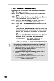
... the option Start Create Process and press to setup hard disk for data protection from the option Create Array. If you wish to install the SATA hard disks and set RAID 1 configuration. 2.9.2.2 Guide to Configure RAID 1 Please enter "VIA Tech RAID BIOS Utility" to set the array mode...your computer. You can find more configuration details in the support CD: .. \ RAID SETUP \ RAID 0.PDF 3. If you wish to install the SATA hard disks alone without making RAID setup, please refer to illustrate the three types of RAID system setting. STEP 3: Start the configuration from the menu...
... the option Start Create Process and press to setup hard disk for data protection from the option Create Array. If you wish to install the SATA hard disks and set RAID 1 configuration. 2.9.2.2 Guide to Configure RAID 1 Please enter "VIA Tech RAID BIOS Utility" to set the array mode...your computer. You can find more configuration details in the support CD: .. \ RAID SETUP \ RAID 0.PDF 3. If you wish to install the SATA hard disks alone without making RAID setup, please refer to illustrate the three types of RAID system setting. STEP 3: Start the configuration from the menu...
