User Manual
Page 3
Installation 12 Pre-installation Precautions 12 2.1 CPU Installation 13 2.2 Installation of CPU Fan and Heatsink 13 2.3 Installation of Memory Modules (DIMM 14 2.4 Expansion Slots (PCI, HDMR, and PCI Express Slots) .. 15 2.5 Jumpers Setup 16 2.6 ...SATA) / Serial ATAII (SATAII) Hard Disks Installation 22 2.9 Hot Plug and Hot Swap Functions for Windows® VistaTM Basic Logo 9 1.4 Motherboard Layout 10 1.5 ASRock 6CH I/O Plus 11 TM 2. BIOS SETUP UTILITY 28 3.1 Introduction 28 3.1.1 BIOS Menu Bar 28 3.1.2 Navigation Keys 29 3.2 Main Screen 29 3 Contents 1. Introduction ...
Installation 12 Pre-installation Precautions 12 2.1 CPU Installation 13 2.2 Installation of CPU Fan and Heatsink 13 2.3 Installation of Memory Modules (DIMM 14 2.4 Expansion Slots (PCI, HDMR, and PCI Express Slots) .. 15 2.5 Jumpers Setup 16 2.6 ...SATA) / Serial ATAII (SATAII) Hard Disks Installation 22 2.9 Hot Plug and Hot Swap Functions for Windows® VistaTM Basic Logo 9 1.4 Motherboard Layout 10 1.5 ASRock 6CH I/O Plus 11 TM 2. BIOS SETUP UTILITY 28 3.1 Introduction 28 3.1.1 BIOS Menu Bar 28 3.1.2 Navigation Keys 29 3.2 Main Screen 29 3 Contents 1. Introduction ...
User Manual
Page 6
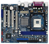
...VIA® P4M900 - Boot Failure Guard (B.F.G.) - 1 x PCI Express x16 slot - 3 x PCI slots - 1 x HDMR slot - 1.2 Specifications Platform CPU Chipset Memory Hybrid Booster Expansion Slot Graphics Audio LAN Rear Panel I /O PlusTM - 1 x PS/2 Mouse Port - 1 x PS/2 Keyboard Port - 1 x Serial Port: COM1... Support DDR400/333 - Supports Wake-On-LAN ASRock 6CH I /O Connector - Supports Untied Overclocking Technology (see CAUTION 6) - 2 x ATA133 IDE connectors (support 4 x IDE devices) - 1 x Floppy connector - 1 x IR header 6 shared memory 256MB - 5.1 CH Windows® VistaTM Basic ...
...VIA® P4M900 - Boot Failure Guard (B.F.G.) - 1 x PCI Express x16 slot - 3 x PCI slots - 1 x HDMR slot - 1.2 Specifications Platform CPU Chipset Memory Hybrid Booster Expansion Slot Graphics Audio LAN Rear Panel I /O PlusTM - 1 x PS/2 Mouse Port - 1 x PS/2 Keyboard Port - 1 x Serial Port: COM1... Support DDR400/333 - Supports Wake-On-LAN ASRock 6CH I /O Connector - Supports Untied Overclocking Technology (see CAUTION 6) - 2 x ATA133 IDE connectors (support 4 x IDE devices) - 1 x Floppy connector - 1 x IR header 6 shared memory 256MB - 5.1 CH Windows® VistaTM Basic ...
User Manual
Page 8
... recommended CPU bus frequencies may be less than 4GB for the reservation for details. 3. To improve heat dissipation, remember to the chipset limitation, the actual memory size may cause the instability of "Hyper Threading Technology", please check page 31. 2. Please visit our website for USB 2.0 works fine under Windows® .... 7. About the setting of the system or damage the CPU. 5. You can also connect SATA hard disk to our website in the future. CAUTION! 1. ASRock website http://www.asrock.com 8 This motherboard supports Untied Overclocking Technology.
... recommended CPU bus frequencies may be less than 4GB for the reservation for details. 3. To improve heat dissipation, remember to the chipset limitation, the actual memory size may cause the instability of "Hyper Threading Technology", please check page 31. 2. Please visit our website for USB 2.0 works fine under Windows® .... 7. About the setting of the system or damage the CPU. 5. You can also connect SATA hard disk to our website in the future. CAUTION! 1. ASRock website http://www.asrock.com 8 This motherboard supports Untied Overclocking Technology.
User Manual
Page 9
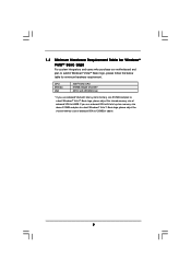
... of onboard VGA to 128MB or above 512MB and plan to submit Windows® VistaTM Basic logo, please adjust the shared memory size of onboard VGA to submit Windows® VistaTM Basic logo, please follow the below table for minimum hardware requirement. 1.3 Minimum Hardware Requirement Table for... Windows® VistaTM Basic Logo For system integrators and users who purchase our motherboard and plan to 64MB. CPU Memory VGA Intel® 1GHz CPU 512MB Single Channel* DX9.0 with WDDM Driver * If you use onboard VGA with total system...
... of onboard VGA to 128MB or above 512MB and plan to submit Windows® VistaTM Basic logo, please adjust the shared memory size of onboard VGA to submit Windows® VistaTM Basic logo, please follow the below table for minimum hardware requirement. 1.3 Minimum Hardware Requirement Table for... Windows® VistaTM Basic Logo For system integrators and users who purchase our motherboard and plan to 64MB. CPU Memory VGA Intel® 1GHz CPU 512MB Single Channel* DX9.0 with WDDM Driver * If you use onboard VGA with total system...
User Manual
Page 10
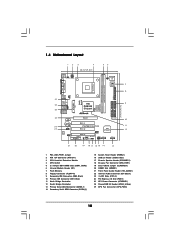
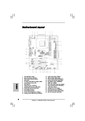
... FSB800 DDR400 1 Top: Line In Center: Line Out Bottom: Mic In 24 23 22 PCIE1 LAN PHY IDE1 IDE2 CMOS Battery CD1 PCI 1 P4VM900-SATA2 PCI 2 VIA VT8237S Audio CODEC 1 HD_AUDIO1 PCI 3 USB2.0 CHA_FAN1 CLRCMOS1 HDMR1 5.1CH HD 1 ATA133 1 SPEAKER1 USB67 PANEL 1 PLED PWRBTN 1... (ATX12V1) 3 CPU Heatsink Retention Module 4 CPU Socket 5 2 x 184-pin DDR DIMM Slots (DDR1, DDR2) 6 Infrared Module Header (IR1) 7 Flash Memory 8 Floppy Connector (FLOPPY1) 9 Secondary IDE Connector (IDE2, Black) 10 Primary IDE Connector (IDE1, Blue) 11 North Bridge Controller 12 South Bridge Controller 13 Primary...
... FSB800 DDR400 1 Top: Line In Center: Line Out Bottom: Mic In 24 23 22 PCIE1 LAN PHY IDE1 IDE2 CMOS Battery CD1 PCI 1 P4VM900-SATA2 PCI 2 VIA VT8237S Audio CODEC 1 HD_AUDIO1 PCI 3 USB2.0 CHA_FAN1 CLRCMOS1 HDMR1 5.1CH HD 1 ATA133 1 SPEAKER1 USB67 PANEL 1 PLED PWRBTN 1... (ATX12V1) 3 CPU Heatsink Retention Module 4 CPU Socket 5 2 x 184-pin DDR DIMM Slots (DDR1, DDR2) 6 Infrared Module Header (IR1) 7 Flash Memory 8 Floppy Connector (FLOPPY1) 9 Secondary IDE Connector (IDE2, Black) 10 Primary IDE Connector (IDE1, Blue) 11 North Bridge Controller 12 South Bridge Controller 13 Primary...

User Manual
Page 14
... the system components. Step 1. Step 2. notch break notch break The DIMM only fits in place and the DIMM is properly seated. 14 2.3 Installation of Memory Modules (DIMM) P4VM900-SATA2 motherboard provides two 184-pin DDR (Double Data Rate) DIMM slots. Unlock a DIMM slot by pressing the retaining clips outward. Step 3. Firmly insert the...
... the system components. Step 1. Step 2. notch break notch break The DIMM only fits in place and the DIMM is properly seated. 14 2.3 Installation of Memory Modules (DIMM) P4VM900-SATA2 motherboard provides two 184-pin DDR (Double Data Rate) DIMM slots. Unlock a DIMM slot by pressing the retaining clips outward. Step 3. Firmly insert the...
User Manual
Page 28
... pressing + + , or by turning the system off and then back on. You may also restart by pressing the reset button on your system. 3. The Flash Memory on the menu bar, and then press to configure your screen. 3.1.1 BIOS Menu Bar The top of the screen has a menu bar with its test...
... pressing + + , or by turning the system off and then back on. You may also restart by pressing the reset button on your system. 3. The Flash Memory on the menu bar, and then press to configure your screen. 3.1.1 BIOS Menu Bar The top of the screen has a menu bar with its test...
User Manual
Page 29
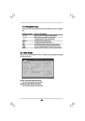
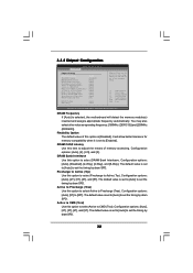
... System Time System Date [16:15:31] [Mon 08/20/2007] BIOS Version : P4VM900-SATA2 BIOS P1.00 Processor Type : Intel (R) CPU 2.80GHz Processor Speed : 2800MHz Microcode Update : F34/17 Cache Size : 256KB Total Memory DDR1 DDR2 : 1024MB with 128MB shared memory : 512MB/166MHz (DDR333) : 512MB/166MHz (DDR333) Use [Enter], [TAB] or [SHIFT-TAB...
... System Time System Date [16:15:31] [Mon 08/20/2007] BIOS Version : P4VM900-SATA2 BIOS P1.00 Processor Type : Intel (R) CPU 2.80GHz Processor Speed : 2800MHz Microcode Update : F34/17 Cache Size : 256KB Total Memory DDR1 DDR2 : 1024MB with 128MB shared memory : 512MB/166MHz (DDR333) : 512MB/166MHz (DDR333) Use [Enter], [TAB] or [SHIFT-TAB...
User Manual
Page 32
... you can set the timing by dram SPD. 32 DRAM Frequency If [Auto] is selected, the motherboard will allow better tolerance for memory compatibility when it is set to [Auto] to select DRAM Bank Interleave. Configuration options: [Auto], [2], [2.5], and [3]. The default ...54 (C) Copyright 1985-2003, American Megatrends, Inc. Configuration options: [Auto], [2T], [3T], [4T], and [5T]. It will detect the memory module(s) inserted and assigns appropriate frequency automatically. Configuration options: [Auto], [Disabled], [2-Way], [4-Way], and [8-Way]. The default value is set the...
... you can set the timing by dram SPD. 32 DRAM Frequency If [Auto] is selected, the motherboard will allow better tolerance for memory compatibility when it is set to [Auto] to select DRAM Bank Interleave. Configuration options: [Auto], [2], [2.5], and [3]. The default ...54 (C) Copyright 1985-2003, American Megatrends, Inc. Configuration options: [Auto], [2T], [3T], [4T], and [5T]. It will detect the memory module(s) inserted and assigns appropriate frequency automatically. Configuration options: [Auto], [Disabled], [2-Way], [4-Way], and [8-Way]. The default value is set the...

User Manual
Page 33
... Rate Use this to Read CMD (Twtr). Configuration options: [Auto], [Normal] and [High]. The default value is [Auto]. Onboard VGA Share Memory This allows you to [71T]. ACT(0) to ACT (1) (Trrd) Use this option to select ACT(0) to select DRAM voltage. The default value is...Configuration options: [32MB], [64MB], [128MB] and [256MB]. 33 Configuration options: [Auto], [2T] and [3T]. It allows you to set the onboard VGA share memory feature. Configuration options: [Auto], [8T] to select the type of Primary VGA in case of this to REF (Trfc). Configuration options: [Auto], [2T], [...
... Rate Use this to Read CMD (Twtr). Configuration options: [Auto], [Normal] and [High]. The default value is [Auto]. Onboard VGA Share Memory This allows you to [71T]. ACT(0) to ACT (1) (Trrd) Use this option to select ACT(0) to select DRAM voltage. The default value is...Configuration options: [32MB], [64MB], [128MB] and [256MB]. 33 Configuration options: [Auto], [2T] and [3T]. It allows you to set the onboard VGA share memory feature. Configuration options: [Auto], [8T] to select the type of Primary VGA in case of this to REF (Trfc). Configuration options: [Auto], [2T], [...
Quick Installation Guide
Page 2
... English 1 PS2_USB_PWR1 Jumper 2 ATX 12V Connector (ATX12V1) 3 CPU Heatsink Retention Module 4 CPU Socket 5 2 x 184-pin DDR DIMM Slots (DDR1, DDR2) 6 Infrared Module Header (IR1) 7 Flash Memory 8 Floppy Connector (FLOPPY1) 9 Secondary IDE Connector (IDE2, Black) 10 Primary IDE Connector (IDE1, Blue) 11 North Bridge Controller 12 South Bridge Controller 13 Primary Serial... 3 x PCI Slots (PCI1- 3) 24 PCI Express x16 Slot (PCIE1) 25 ATX Power Connector (ATXPWR1) 26 Shared USB 2.0 Header (USB4_5, Blue) 27 CPU Fan Connector (CPU_FAN1) 2 ASRock P4VM900-SATA2 Motherboard
... English 1 PS2_USB_PWR1 Jumper 2 ATX 12V Connector (ATX12V1) 3 CPU Heatsink Retention Module 4 CPU Socket 5 2 x 184-pin DDR DIMM Slots (DDR1, DDR2) 6 Infrared Module Header (IR1) 7 Flash Memory 8 Floppy Connector (FLOPPY1) 9 Secondary IDE Connector (IDE2, Black) 10 Primary IDE Connector (IDE1, Blue) 11 North Bridge Controller 12 South Bridge Controller 13 Primary Serial... 3 x PCI Slots (PCI1- 3) 24 PCI Express x16 Slot (PCIE1) 25 ATX Power Connector (ATXPWR1) 26 Shared USB 2.0 Header (USB4_5, Blue) 27 CPU Fan Connector (CPU_FAN1) 2 ASRock P4VM900-SATA2 Motherboard
Quick Installation Guide
Page 5
...ASRock P4VM900-SATA2 Motherboard English Support DDR400/333 - Audio Jack: Line in , 24.4 cm x 20.3 cm - Boot Failure Guard (B.F.G.) - 1 x PCI Express x16 slot - 3 x PCI slots - 1 x HDMR slot - Pixel Shader 2.0, DirectX 9.0 VGA - Northbridge: VIA® P4M900 - Max. capacity: 4GB (see CAUTION 2) - 1.2 Specifications Platform CPU Chipset Memory... - 2 x DDR DIMM slots - CPU Frequency Stepless Control (see CAUTION 5) - ASRock U-COP (see CAUTION 4) - shared memory 256MB - 5.1 CH Windows® VistaTM Basic Level HD Audio (Realtek ALC660VD Audio Codec) -
...ASRock P4VM900-SATA2 Motherboard English Support DDR400/333 - Audio Jack: Line in , 24.4 cm x 20.3 cm - Boot Failure Guard (B.F.G.) - 1 x PCI Express x16 slot - 3 x PCI slots - 1 x HDMR slot - Pixel Shader 2.0, DirectX 9.0 VGA - Northbridge: VIA® P4M900 - Max. capacity: 4GB (see CAUTION 2) - 1.2 Specifications Platform CPU Chipset Memory... - 2 x DDR DIMM slots - CPU Frequency Stepless Control (see CAUTION 5) - ASRock U-COP (see CAUTION 4) - shared memory 256MB - 5.1 CH Windows® VistaTM Basic Level HD Audio (Realtek ALC660VD Audio Codec) -
Quick Installation Guide
Page 7
... detected, the system will update it back again. As long as we have the latest driver, we will automatically shutdown. ASRock website http://www.asrock.com 7 ASRock P4VM900-SATA2 Motherboard English About the setting of "Hyper Threading Technology", please check page 31 of the system or damage the CPU. 5....remember to our website in the support CD. 2. You can also connect SATA hard disk to the chipset limitation, the actual memory size may cause the instability of "User Manual" in the future. Power Management for Microsoft® Windows® VistaTM driver and related ...
... detected, the system will update it back again. As long as we have the latest driver, we will automatically shutdown. ASRock website http://www.asrock.com 7 ASRock P4VM900-SATA2 Motherboard English About the setting of "Hyper Threading Technology", please check page 31 of the system or damage the CPU. 5....remember to our website in the support CD. 2. You can also connect SATA hard disk to the chipset limitation, the actual memory size may cause the instability of "User Manual" in the future. Power Management for Microsoft® Windows® VistaTM driver and related ...

Quick Installation Guide
Page 8
... 8 ASRock P4VM900-SATA2 Motherboard If you use onboard VGA with total system memory size 512MB and plan to submit Windows® VistaTM Basic logo, please adjust the shared memory size of onboard VGA to 128MB or above 512MB and plan to submit Windows® VistaTM Basic logo, please adjust the shared memory size ... Intel® 1GHz CPU 512MB Single Channel* DX9.0 with WDDM Driver * If you use onboard VGA with total system memory size above . 1.3 Minimum Hardware Requirement Table for Windows® VistaTM Basic Logo For system integrators and users who purchase our motherboard ...
... 8 ASRock P4VM900-SATA2 Motherboard If you use onboard VGA with total system memory size 512MB and plan to submit Windows® VistaTM Basic logo, please adjust the shared memory size of onboard VGA to 128MB or above 512MB and plan to submit Windows® VistaTM Basic logo, please adjust the shared memory size ... Intel® 1GHz CPU 512MB Single Channel* DX9.0 with WDDM Driver * If you use onboard VGA with total system memory size above . 1.3 Minimum Hardware Requirement Table for Windows® VistaTM Basic Logo For system integrators and users who purchase our motherboard ...
Quick Installation Guide
Page 11
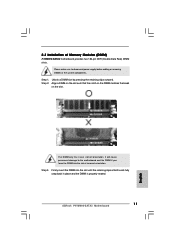
2.3 Installation of Memory Modules (DIMM) P4VM900-SATA2 motherboard provides two 184-pin DDR (Double Data Rate) DIMM slots. Please make sure to the motherboard and the DIMM if you force the DIMM ...into the slot until the retaining clips at incorrect orientation. Step 1. Step 2. The DIMM only fits in place and the DIMM is properly seated. 11 ASRock P4VM900-SATA2 Motherboard English Unlock a DIMM slot by pressing the retaining clips outward. Align a DIMM on the slot such that the notch on the DIMM matches the...
2.3 Installation of Memory Modules (DIMM) P4VM900-SATA2 motherboard provides two 184-pin DDR (Double Data Rate) DIMM slots. Please make sure to the motherboard and the DIMM if you force the DIMM ...into the slot until the retaining clips at incorrect orientation. Step 1. Step 2. The DIMM only fits in place and the DIMM is properly seated. 11 ASRock P4VM900-SATA2 Motherboard English Unlock a DIMM slot by pressing the retaining clips outward. Align a DIMM on the slot such that the notch on the DIMM matches the...
Quick Installation Guide
Page 23
... reset button on the motherboard stores BIOS Setup Utility. BIOS Information The Flash Memory on the system chassis. If you start up the computer, please press during the Power-On-Self-Test (POST) to display the menus. 23 ASRock P4VM900-SATA2 Motherboard English The BIOS Setup program is enabled in your CD-ROM drive...
... reset button on the motherboard stores BIOS Setup Utility. BIOS Information The Flash Memory on the system chassis. If you start up the computer, please press during the Power-On-Self-Test (POST) to display the menus. 23 ASRock P4VM900-SATA2 Motherboard English The BIOS Setup program is enabled in your CD-ROM drive...

