
User Manual
Page 3
...Functions 21 2.13 Untied Overclocking Technology 22 3. Introduction 5 1.1 Package Contents 5 1.2 Specifications 6 1.3 Motherboard Layout 9 1.4 ASRock I/O Plus 10 TM 2. BIOS SETUP UTILITY 23 3.1 Introduction 23 3.1.1 BIOS Menu Bar 23 3.1.2 Navigation Keys 24 3.2 Main Screen 24 3.3 ...Advanced Screen 25 3.3.1 CPU Configuration 25 3.3.2 Chipset Configuration 27 3.3.3 ACPI Configuration 30 3.3.4 IDE Configuration 31 3.3.5 PCIPnP Configuration 33 3.3.6 Floppy Configuration 33...
...Functions 21 2.13 Untied Overclocking Technology 22 3. Introduction 5 1.1 Package Contents 5 1.2 Specifications 6 1.3 Motherboard Layout 9 1.4 ASRock I/O Plus 10 TM 2. BIOS SETUP UTILITY 23 3.1 Introduction 23 3.1.1 BIOS Menu Bar 23 3.1.2 Navigation Keys 24 3.2 Main Screen 24 3.3 ...Advanced Screen 25 3.3.1 CPU Configuration 25 3.3.2 Chipset Configuration 27 3.3.3 ACPI Configuration 30 3.3.4 IDE Configuration 31 3.3.5 PCIPnP Configuration 33 3.3.6 Floppy Configuration 33...

User Manual
Page 5
...-bystep guide to change without further notice. ASRock website http://www.asrock.com 1.1 Package Contents ASRock P4VM890 Motherboard (Micro ATX Form Factor: 9.6-in x 8.0-in, 24.4 cm x 20.3 cm) ASRock P4VM890 Quick Installation Guide ASRock P4VM890 Support CD One 80-conductor Ultra ATA 66...Ribbon Cable for purchasing ASRock P4VM890 motherboard, a reliable motherboard produced under ASRock's consistently stringent quality control. In this manual will be subject to the hardware installation. You may find the latest VGA cards and CPU support lists on ASRock website without notice. ...
...-bystep guide to change without further notice. ASRock website http://www.asrock.com 1.1 Package Contents ASRock P4VM890 Motherboard (Micro ATX Form Factor: 9.6-in x 8.0-in, 24.4 cm x 20.3 cm) ASRock P4VM890 Quick Installation Guide ASRock P4VM890 Support CD One 80-conductor Ultra ATA 66...Ribbon Cable for purchasing ASRock P4VM890 motherboard, a reliable motherboard produced under ASRock's consistently stringent quality control. In this manual will be subject to the hardware installation. You may find the latest VGA cards and CPU support lists on ASRock website without notice. ...
User Manual
Page 6
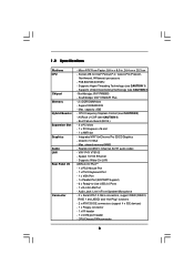
... 1) - Integrated VIA® UniChrome Pro 3D/2D Graphics - Realtek ALC653 5.1channel AC'97 audio codec - Supports Hyper-Threading Technology (see CAUTION 4) - CPU Frequency Stepless Control (see CAUTION 2) - Supports Wake-On-LAN ASRock I /O Connector - Southbridge: VIA® VT8237R Plus - 2 x DDR DIMM slots - Boot Failure Guard (B.F.G.) - 3 x PCI slots - 1 x PCI Express x16 slot - 1 x AMR slot...
... 1) - Integrated VIA® UniChrome Pro 3D/2D Graphics - Realtek ALC653 5.1channel AC'97 audio codec - Supports Hyper-Threading Technology (see CAUTION 4) - CPU Frequency Stepless Control (see CAUTION 2) - Supports Wake-On-LAN ASRock I /O Connector - Southbridge: VIA® VT8237R Plus - 2 x DDR DIMM slots - Boot Failure Guard (B.F.G.) - 3 x PCI slots - 1 x PCI Express x16 slot - 1 x AMR slot...

User Manual
Page 7
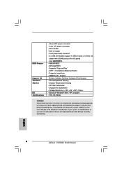
... USB45 ports on the I/O panel) (see CAUTION 5) - 4Mb AMI BIOS - Drivers, Utilities, AntiVirus Software (Trial Version) - CPU Fan Tachometer - It should be done at your system. AMI Legal BIOS - ACPI 1.1 Compliance Wake Up Events - CPU Temperature Sensing - Voltage Monitoring: +12V, +5V, +3.3V, Vcore - We are shared with overclocking, including adjusting the setting...
... USB45 ports on the I/O panel) (see CAUTION 5) - 4Mb AMI BIOS - Drivers, Utilities, AntiVirus Software (Trial Version) - CPU Fan Tachometer - It should be done at your system. AMI Legal BIOS - ACPI 1.1 Compliance Wake Up Events - CPU Temperature Sensing - Voltage Monitoring: +12V, +5V, +3.3V, Vcore - We are shared with overclocking, including adjusting the setting...

User Manual
Page 8
CAUTION! 1. This motherboard supports Untied Overclocking Technology. While CPU overheat is not recommended to spray thermal grease between the CPU and the heatsink when you resume the system, please check if the CPU fan on page 22 for USB 2.0 works fine under Microsoft® Windows® XP SP1 ...To improve heat dissipation, remember to perform over-clocking. Before you install the PC system. 5. Frequencies other than the recommended CPU bus frequencies may cause the instability of "Hyper Threading Technology", please check page 26. 2. About the setting of the system or ...
CAUTION! 1. This motherboard supports Untied Overclocking Technology. While CPU overheat is not recommended to spray thermal grease between the CPU and the heatsink when you resume the system, please check if the CPU fan on page 22 for USB 2.0 works fine under Microsoft® Windows® XP SP1 ...To improve heat dissipation, remember to perform over-clocking. Before you install the PC system. 5. Frequencies other than the recommended CPU bus frequencies may cause the instability of "Hyper Threading Technology", please check page 26. 2. About the setting of the system or ...
User Manual
Page 9
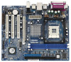
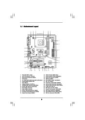
... 28 ATX Power Connector (ATXPWR1) 14 Secondary Serial ATA Connector (SATA2) 29 Shared USB 2.0 Header (USB4_5, Blue) 15 System Panel Header (PANEL1) 30 CPU Fan Connector (CPU_FAN1) 9 1.3 Motherboard Layout 12 3 4 20.3cm (8.0 in) 56 PS2 Keyboard PS2 Mouse 1 PS2_USB_PWR1 ATX12V1 1 IR1 Super I/O 4Mb ... USB4_5 CHA_FAN1 5.1CH LAN PHY CMOS Battery CD1 AUX1 Audio AUDIO1 CODEC 1 JR1 JL1 CLRCMOS1 RoHS PCIE1 PCI EXPRESS IDE1 IDE2 PCI 1 ` P4VM890 PCI 2 PCI 3 ATA133 AMR1 1 COM1 1 USB67 1 SPEAKER1 PANEL 1 PLED PWRBTN 1 HDLED RESET VIA VT8237R Plus SATA2 SATA1 SATA 9...
... 28 ATX Power Connector (ATXPWR1) 14 Secondary Serial ATA Connector (SATA2) 29 Shared USB 2.0 Header (USB4_5, Blue) 15 System Panel Header (PANEL1) 30 CPU Fan Connector (CPU_FAN1) 9 1.3 Motherboard Layout 12 3 4 20.3cm (8.0 in) 56 PS2 Keyboard PS2 Mouse 1 PS2_USB_PWR1 ATX12V1 1 IR1 Super I/O 4Mb ... USB4_5 CHA_FAN1 5.1CH LAN PHY CMOS Battery CD1 AUX1 Audio AUDIO1 CODEC 1 JR1 JL1 CLRCMOS1 RoHS PCIE1 PCI EXPRESS IDE1 IDE2 PCI 1 ` P4VM890 PCI 2 PCI 3 ATA133 AMR1 1 COM1 1 USB67 1 SPEAKER1 PANEL 1 PLED PWRBTN 1 HDLED RESET VIA VT8237R Plus SATA2 SATA1 SATA 9...

User Manual
Page 12
... to The Socket Marked Corner STEP 4: Push Down And Lock The Socket Lever 2.2 Installation of the CPU fan and the heatsink. 12 The CPU fits only in good contact with each other. Make sure that its marked corner matches the base of the pins. Step 2. It requires ...larger heatsink and cooling fan to a 90° angle. 2.1 CPU Installation Step 1. Unlock the socket by lifting the lever up to dissipate heat. Position the CPU directly above the socket such that the CPU and the heatsink are securely fastened and in one correct orientation. Lift Lever Up...
... to The Socket Marked Corner STEP 4: Push Down And Lock The Socket Lever 2.2 Installation of the CPU fan and the heatsink. 12 The CPU fits only in good contact with each other. Make sure that its marked corner matches the base of the pins. Step 2. It requires ...larger heatsink and cooling fan to a 90° angle. 2.1 CPU Installation Step 1. Unlock the socket by lifting the lever up to dissipate heat. Position the CPU directly above the socket such that the CPU and the heatsink are securely fastened and in one correct orientation. Lift Lever Up...

User Manual
Page 18
...PLED+ PLEDPWRBTN# GND 1 DUMMY RESET# GND HDLEDHDLED+ 1 SPEAKER DUMMY DUMMY +5V This header accommodates several system front panel functions. Please connect the CPU fan cable to this connector and match the black wire to the ground pin. Chassis Fan Connector (3-pin CHA_FAN1) (see p.9, No. 27) CHA_FAN_SPEED... +12V GND CPU Fan Connector (3-pin CPU_FAN1) (see p.9, No. 30) GND +12V CPU_FAN_SPEED ATX Power Connector (20-pin ATXPWR1) (see p.9, No. 2) ...
...PLED+ PLEDPWRBTN# GND 1 DUMMY RESET# GND HDLEDHDLED+ 1 SPEAKER DUMMY DUMMY +5V This header accommodates several system front panel functions. Please connect the CPU fan cable to this connector and match the black wire to the ground pin. Chassis Fan Connector (3-pin CHA_FAN1) (see p.9, No. 27) CHA_FAN_SPEED... +12V GND CPU Fan Connector (3-pin CPU_FAN1) (see p.9, No. 30) GND +12V CPU_FAN_SPEED ATX Power Connector (20-pin ATXPWR1) (see p.9, No. 2) ...

User Manual
Page 22
... frequency in the fixed mode so that FSB can operate under a more stable overclocking environment. Therefore, CPU FSB is in the following item. You may set "CPU Host Frequency" option of BIOS setup to [Auto], which means during overclocking, but PCI / PCIE bus is untied during overclocking, FSB enjoys better margin due...
... frequency in the fixed mode so that FSB can operate under a more stable overclocking environment. Therefore, CPU FSB is in the following item. You may set "CPU Host Frequency" option of BIOS setup to [Auto], which means during overclocking, but PCI / PCIE bus is untied during overclocking, FSB enjoys better margin due...

User Manual
Page 24
... UTILITY Main Advanced H/W Monitor Boot Security Exit System Overview System Time System Date [16:15:31] [Mon 12/25/2006] BIOS Version : P4VM890 BIOS P1.00 Processor Type : Intel (R) Pentium (R) 4 CPU 2.40GHz Processor Speed : 2400MHz Microcode Update : F33/C Cache Size : 1024KB Total Memory DDR1 DDR2 : 256MB with 64MB shared memory : 256MB/166MHz...
... UTILITY Main Advanced H/W Monitor Boot Security Exit System Overview System Time System Date [16:15:31] [Mon 12/25/2006] BIOS Version : P4VM890 BIOS P1.00 Processor Type : Intel (R) Pentium (R) 4 CPU 2.40GHz Processor Speed : 2400MHz Microcode Update : F33/C Cache Size : 1024KB Total Memory DDR1 DDR2 : 256MB with 64MB shared memory : 256MB/166MHz...

User Manual
Page 25
...F1 General Help F9 Load Defaults F10 Save and Exit ESC Exit v02.54 (C) Copyright 1985-2003, American Megatrends, Inc. The actual CPU host frequency will show in below sections may cause system to malfunction. Mode] [Enabled] Locked 18 [Disabled] [Enabled] [Enabled] ...-2003, American Megatrends, Inc. 3.3 Advanced Screen In this section, you may cause the system to malfunction. 3.3.1 CPU Configuration BIOS SETUP UTILITY Advanced CPU Configuration CPU Host Frequency Actual Frequency (MHz) Spread Spectrum PCIE/PCI operation mode Boot Failure Guard Ratio Status Ratio Actual Value Max...
...F1 General Help F9 Load Defaults F10 Save and Exit ESC Exit v02.54 (C) Copyright 1985-2003, American Megatrends, Inc. The actual CPU host frequency will show in below sections may cause system to malfunction. Mode] [Enabled] Locked 18 [Disabled] [Enabled] [Enabled] ...-2003, American Megatrends, Inc. 3.3 Advanced Screen In this section, you may cause the system to malfunction. 3.3.1 CPU Configuration BIOS SETUP UTILITY Advanced CPU Configuration CPU Host Frequency Actual Frequency (MHz) Spread Spectrum PCIE/PCI operation mode Boot Failure Guard Ratio Status Ratio Actual Value Max...

User Manual
Page 26
...mode]. Configuration options: [Async. Ratio Actual Value This is [Auto]. This option will find an item Ratio CMOS Setting appears to keep the CPU from overheated. Spread Spectrum The default value of this option is a read -only item, which displays the ratio actual value of this motherboard. ... support CPUs with disable. Hyper Threading Technology To enable this technology, such as Microsoft® Windows® XP. Max CPUID Value Limit For Prescott CPU only, some OSes (ex. The default value is "Locked" or "Unlocked". If you changing the ratio value of this to the core speed...
...mode]. Configuration options: [Async. Ratio Actual Value This is [Auto]. This option will find an item Ratio CMOS Setting appears to keep the CPU from overheated. Spread Spectrum The default value of this option is a read -only item, which displays the ratio actual value of this motherboard. ... support CPUs with disable. Hyper Threading Technology To enable this technology, such as Microsoft® Windows® XP. Max CPUID Value Limit For Prescott CPU only, some OSes (ex. The default value is "Locked" or "Unlocked". If you changing the ratio value of this to the core speed...

User Manual
Page 36
... ESC Exit v02.54 (C) Copyright 1985-2003, American Megatrends, Inc. 36 BIOS SETUP UTILITY Main Advanced H/W Monitor Boot Security Exit Hardware Health Event Monitoring CPU Temperature M / B Temperature CPU Fan Speed Chassis Fan Speed Vcore + 3.30V + 5.00V + 12.00V : 37 C / 98 F : 31 C / 87 F : 2463 RPM : N/A : 1.629V : ... your system, including the parameters of the hardware on your system for you to monitor the status of the CPU temperature, motherboard temperature, CPU fan speed, chassis fan speed, and the critical voltage. Select Screen Select Item Enter Go to configure the ...
... ESC Exit v02.54 (C) Copyright 1985-2003, American Megatrends, Inc. 36 BIOS SETUP UTILITY Main Advanced H/W Monitor Boot Security Exit Hardware Health Event Monitoring CPU Temperature M / B Temperature CPU Fan Speed Chassis Fan Speed Vcore + 3.30V + 5.00V + 12.00V : 37 C / 98 F : 31 C / 87 F : 2463 RPM : N/A : 1.629V : ... your system, including the parameters of the hardware on your system for you to monitor the status of the CPU temperature, motherboard temperature, CPU fan speed, chassis fan speed, and the critical voltage. Select Screen Select Item Enter Go to configure the ...

Quick Installation Guide
Page 2
... Slots (PCI1- 3) 26 PCI Express x16 Slot (PCIE1) 27 Chassis Fan Connector (CHA_FAN1) 28 ATX Power Connector (ATXPWR1) 29 Shared USB 2.0 Header (USB4_5, Blue) 30 CPU Fan Connector (CPU_FAN1) 2 ASRock P4VM890 Motherboard Motherboard Layout English 1 PS2_USB_PWR1 Jumper 2 ATX 12V Connector (ATX12V1) 3 CPU Heatsink Retention Module 4 CPU Socket 5 2 x 184-pin DDR DIMM Slots (DDR1, DDR2;
... Slots (PCI1- 3) 26 PCI Express x16 Slot (PCIE1) 27 Chassis Fan Connector (CHA_FAN1) 28 ATX Power Connector (ATXPWR1) 29 Shared USB 2.0 Header (USB4_5, Blue) 30 CPU Fan Connector (CPU_FAN1) 2 ASRock P4VM890 Motherboard Motherboard Layout English 1 PS2_USB_PWR1 Jumper 2 ATX 12V Connector (ATX12V1) 3 CPU Heatsink Retention Module 4 CPU Socket 5 2 x 184-pin DDR DIMM Slots (DDR1, DDR2;

Quick Installation Guide
Page 4
... One Serial ATA (SATA) Cable (Optional) One Serial ATA (SATA) HDD Power Cable (Optional) One ASRock I/O PlusTM Shield One COM Port Bracket 4 ASRock P4VM890 Motherboard English You may find the latest VGA cards and CPU support lists on ASRock website without notice. 1. More detailed information of this manual occur, the updated version will be subject...
... One Serial ATA (SATA) Cable (Optional) One Serial ATA (SATA) HDD Power Cable (Optional) One ASRock I/O PlusTM Shield One COM Port Bracket 4 ASRock P4VM890 Motherboard English You may find the latest VGA cards and CPU support lists on ASRock website without notice. 1. More detailed information of this manual occur, the updated version will be subject...

Quick Installation Guide
Page 5
... Intel® Pentium® 4 / Celeron® D (Prescott, Northwood, Willamate) processors - Boot Failure Guard (B.F.G.) - 3 x PCI slots - 1 x PCI Express x16 slot - 1 x AMR slot - DirectX 7.0 VGA - CPU/Chassis FAN connector 5 ASRock P4VM890 Motherboard English Micro ATX Form Factor: 9.6-in x 8.0-in /Front Speaker/Microphone - 2 x Serial ATA 1.5 Gb/s connectors, support RAID (RAID 0, RAID 1 and JBOD) and "Hot Plug...
... Intel® Pentium® 4 / Celeron® D (Prescott, Northwood, Willamate) processors - Boot Failure Guard (B.F.G.) - 3 x PCI slots - 1 x PCI Express x16 slot - 1 x AMR slot - DirectX 7.0 VGA - CPU/Chassis FAN connector 5 ASRock P4VM890 Motherboard English Micro ATX Form Factor: 9.6-in x 8.0-in /Front Speaker/Microphone - 2 x Serial ATA 1.5 Gb/s connectors, support RAID (RAID 0, RAID 1 and JBOD) and "Hot Plug...
Quick Installation Guide
Page 6
AMI Legal BIOS - Drivers, Utilities, AntiVirus Software (Trial Version) - CPU Fan Tachometer - Voltage Monitoring: +12V, +5V, +3.3V, Vcore - It should be done at your system. AUX in the BIOS, ... compliant - Supports jumperfree - CPU Temperature Sensing - We are shared with overclocking, including adjusting the setting in header - Front panel audio connector - 2 x USB 2.0 headers (support 4 USB 2.0 ports; 2 of your own risk and expense. ACPI 1.1 Compliance Wake Up Events - Chassis Fan Tachometer - English 6 ASRock P4VM890 Motherboard BIOS Feature Support CD ...
AMI Legal BIOS - Drivers, Utilities, AntiVirus Software (Trial Version) - CPU Fan Tachometer - Voltage Monitoring: +12V, +5V, +3.3V, Vcore - It should be done at your system. AUX in the BIOS, ... compliant - Supports jumperfree - CPU Temperature Sensing - We are shared with overclocking, including adjusting the setting in header - Front panel audio connector - 2 x USB 2.0 headers (support 4 USB 2.0 ports; 2 of your own risk and expense. ACPI 1.1 Compliance Wake Up Events - Chassis Fan Tachometer - English 6 ASRock P4VM890 Motherboard BIOS Feature Support CD ...

Quick Installation Guide
Page 7
...not recommended to spray thermal grease between the CPU and the heatsink when you resume the system, please check if the CPU fan on page 19 for USB 2.0 works fine under Microsoft® Windows® XP SP1 or SP2 / 2000 SP4. 7 ASRock P4VM890 Motherboard English About the setting of "Hyper ...Threading Technology", please check page 26 of the system or damage the CPU. 4. CAUTION! 1.
...not recommended to spray thermal grease between the CPU and the heatsink when you resume the system, please check if the CPU fan on page 19 for USB 2.0 works fine under Microsoft® Windows® XP SP1 or SP2 / 2000 SP4. 7 ASRock P4VM890 Motherboard English About the setting of "Hyper ...Threading Technology", please check page 26 of the system or damage the CPU. 4. CAUTION! 1.

Quick Installation Guide
Page 9
...® Pentium® 4 / Celeron® CPU. 2.1 CPU Installation Step 1. Then connect the CPU fan to improve heat dissipation. Carefully insert the CPU into the socket to avoid bending of CPU Fan and Heatsink This motherboard adopts 478-pin CPU socket to the instruction manuals of the socket lever. English 9 ASRock P4VM890 Motherboard The CPU fits only in place. Step...
...® Pentium® 4 / Celeron® CPU. 2.1 CPU Installation Step 1. Then connect the CPU fan to improve heat dissipation. Carefully insert the CPU into the socket to avoid bending of CPU Fan and Heatsink This motherboard adopts 478-pin CPU socket to the instruction manuals of the socket lever. English 9 ASRock P4VM890 Motherboard The CPU fits only in place. Step...

Quick Installation Guide
Page 15
... pin. Please install the heatsink and the CPU fan before installing ATX 12V connector; otherwise, it is necessary to connect a power supply with ATX 12V plug to this connector and match the black wire to this header. English 15 ASRock P4VM890 Motherboard Chassis Speaker Header (4-pin SPEAKER 1) ...system front panel functions. Failing to do so will cause the failure to this connector. Chassis Fan Connector (3-pin CHA_FAN1) (see p.2, No. 27) CPU Fan Connector (3-pin CPU_FAN1) (see p.2, No. 30) ATX Power Connector (20-pin ATXPWR1) (see p.2, No. 2) Please note that it may ...
... pin. Please install the heatsink and the CPU fan before installing ATX 12V connector; otherwise, it is necessary to connect a power supply with ATX 12V plug to this connector and match the black wire to this header. English 15 ASRock P4VM890 Motherboard Chassis Speaker Header (4-pin SPEAKER 1) ...system front panel functions. Failing to do so will cause the failure to this connector. Chassis Fan Connector (3-pin CHA_FAN1) (see p.2, No. 27) CPU Fan Connector (3-pin CPU_FAN1) (see p.2, No. 30) ATX Power Connector (20-pin ATXPWR1) (see p.2, No. 2) Please note that it may ...


