User Manual
Page 4
... 44 3.1 Introduction 44 3.1.1 BIOS Menu Bar 44 3.1.2 Navigation Keys 45 3.2 Main Screen 45 3.3 Smart Screen 46 3.4 Advanced Screen 46 3.4.1 CPU Configuration 47 3.4.2 Chipset Configuration 50 3.4.3 ACPI Configuration 58 3.4.4 IDE ...
... 44 3.1 Introduction 44 3.1.1 BIOS Menu Bar 44 3.1.2 Navigation Keys 45 3.2 Main Screen 45 3.3 Smart Screen 46 3.4 Advanced Screen 46 3.4.1 CPU Configuration 47 3.4.2 Chipset Configuration 50 3.4.3 ACPI Configuration 58 3.4.4 IDE ...
User Manual
Page 5
... specifications and the BIOS software might be updated, the content of this manual occur, the updated version will be available on ASRock website as well. www.asrock.com/support/index.asp 1.1 Package Contents ASRock P45X3 Deluxe Motherboard (ATX Form Factor: 12.0-in x 9.6-in, 30.5 cm x 24.4 cm) ASRock P45X3 Deluxe Quick Installation Guide ASRock P45X3 Deluxe Support CD One ASRock SLI/XFire Switch...
... specifications and the BIOS software might be updated, the content of this manual occur, the updated version will be available on ASRock website as well. www.asrock.com/support/index.asp 1.1 Package Contents ASRock P45X3 Deluxe Motherboard (ATX Form Factor: 12.0-in x 9.6-in, 30.5 cm x 24.4 cm) ASRock P45X3 Deluxe Quick Installation Guide ASRock P45X3 Deluxe Support CD One ASRock SLI/XFire Switch...
User Manual
Page 7
AMI Legal BIOS - AMBIOS 2.3.1 Support - T. (Intelligent Overclocking Technology) - ACPI 1.1 Compliance Wake Up Events - ASRock OC Tuner (see CAUTION 12) - Hybrid Booster: - CPU Temperature Sensing - O. Intelligent Energy Saver (see CAUTION ...13) - Supports jumperfree - Drivers, Utilities, AntiVirus Software (Trial Version) - ASRock U-COP (see CAUTION 14) - Connector Quick Switch BIOS Feature Support CD Unique Feature Hardware Monitor - 1 x Clear CMOS Switch with LED - 8Mb AMI BIOS - CPU, VCCM, VTT Voltage Multi-adjustment - Instant Boot - CPU Frequency ...
AMI Legal BIOS - AMBIOS 2.3.1 Support - T. (Intelligent Overclocking Technology) - ACPI 1.1 Compliance Wake Up Events - ASRock OC Tuner (see CAUTION 12) - Hybrid Booster: - CPU Temperature Sensing - O. Intelligent Energy Saver (see CAUTION ...13) - Supports jumperfree - Drivers, Utilities, AntiVirus Software (Trial Version) - ASRock U-COP (see CAUTION 14) - Connector Quick Switch BIOS Feature Support CD Unique Feature Hardware Monitor - 1 x Clear CMOS Switch with LED - 8Mb AMI BIOS - CPU, VCCM, VTT Voltage Multi-adjustment - Instant Boot - CPU Frequency ...
User Manual
Page 8
...Threading Technology", please check page 49. 3. Before you implement Dual Channel Memory Technology, make sure to the components and devices of ASRock SLI/XFire Switch Card in advance. 8 Please check the table below for proper installation. 5. We are not responsible for possible damage..., WHQL * For detailed product information, please visit our website: http://www.asrock.com WARNING Please realize that there is a certain risk involved with 64-bit CPU, there is operating in the BIOS, applying Untied Overclocking Technology, or using the thirdparty overclocking tools. About the...
...Threading Technology", please check page 49. 3. Before you implement Dual Channel Memory Technology, make sure to the components and devices of ASRock SLI/XFire Switch Card in advance. 8 Please check the table below for proper installation. 5. We are not responsible for possible damage..., WHQL * For detailed product information, please visit our website: http://www.asrock.com WARNING Please realize that there is a certain risk involved with 64-bit CPU, there is operating in the BIOS, applying Untied Overclocking Technology, or using the thirdparty overclocking tools. About the...
User Manual
Page 9
...allows you can update your hardware devices to surveil your system by hardware monitor function and overclock your BIOS only in Flash ROM. ASRock website: http://www.asrock.com 12. In other than the recommended CPU bus frequencies may cause the instability of Intelligent Energy ...; 2000 OS. You can also connect SATA hard disk to update system BIOS without sacrificing computing performance. 8. Power Management for USB 2.0 works fine under Windows® environment. ASRock website: http://www.asrock.com 13. To improve heat dissipation, remember to spray thermal grease between...
...allows you can update your hardware devices to surveil your system by hardware monitor function and overclock your BIOS only in Flash ROM. ASRock website: http://www.asrock.com 12. In other than the recommended CPU bus frequencies may cause the instability of Intelligent Energy ...; 2000 OS. You can also connect SATA hard disk to update system BIOS without sacrificing computing performance. 8. Power Management for USB 2.0 works fine under Windows® environment. ASRock website: http://www.asrock.com 13. To improve heat dissipation, remember to spray thermal grease between...
User Manual
Page 10
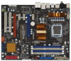
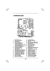
... Center: Bottom: PWR_FAN1 LAN PHY 1 CLRCMOS1 PCIE1 CMOS Battery Intel P45 Chipset Super I/O PCIE2 PCIE3 P45X3 Deluxe FSB2000 IDE1 VIA VT6330 FRONT_1394 1 IR1 1 AUDIO CODEC CD1 PCIE4 CrossFireX PCI Express 2.0 PCIE5 1394a PCI1 RoHS Debug LED 8Mb BIOS 1 HDMI_SPDIF1 1 HD_AUDIO1 COM1 PCI2 FLOPPY1 1 1 TPM1 SPEAKER1 1 PANEL1 PLED PWRBTN 1 HDLED RESET CHA_FAN1 Intel ICH10...
... Center: Bottom: PWR_FAN1 LAN PHY 1 CLRCMOS1 PCIE1 CMOS Battery Intel P45 Chipset Super I/O PCIE2 PCIE3 P45X3 Deluxe FSB2000 IDE1 VIA VT6330 FRONT_1394 1 IR1 1 AUDIO CODEC CD1 PCIE4 CrossFireX PCI Express 2.0 PCIE5 1394a PCI1 RoHS Debug LED 8Mb BIOS 1 HDMI_SPDIF1 1 HD_AUDIO1 COM1 PCI2 FLOPPY1 1 1 TPM1 SPEAKER1 1 PANEL1 PLED PWRBTN 1 HDLED RESET CHA_FAN1 Intel ICH10...
User Manual
Page 25
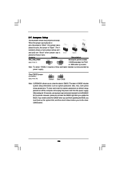
... Description PS2_USB_PWR1 (see p.10 No. 40) 1_2 2_3 Default Clear CMOS Note: CLRCMOS1 allows you do not clear the CMOS right after you update the BIOS. If you need to clear the data in CMOS includes system setup information such as system password, date, time, and system setup parameters. lustration shows... placed on pins, the jumper is "Short". Note: To select +5VSB, it down before you to clear the CMOS when you just finish updating the BIOS, you must boot up events. To clear and reset the system parameters to short pin2 and pin3 on pins, the jumper is "Open". If no...
... Description PS2_USB_PWR1 (see p.10 No. 40) 1_2 2_3 Default Clear CMOS Note: CLRCMOS1 allows you do not clear the CMOS right after you update the BIOS. If you need to clear the data in CMOS includes system setup information such as system password, date, time, and system setup parameters. lustration shows... placed on pins, the jumper is "Short". Note: To select +5VSB, it down before you to clear the CMOS when you just finish updating the BIOS, you must boot up events. To clear and reset the system parameters to short pin2 and pin3 on pins, the jumper is "Open". If no...
User Manual
Page 28
..." , choose "Disable front panel jack detection", and save the change by clicking "OK". Connect Audio_R (RIN) to OUT2_R and Audio_L (LIN) to function correctly. Enter BIOS Setup Utility. F. G. High Definition Audio supports Jack Sensing, but the panel wire on the lower right hand taskbar to [Enabled]. E. To activate the front mic...
..." , choose "Disable front panel jack detection", and save the change by clicking "OK". Connect Audio_R (RIN) to OUT2_R and Audio_L (LIN) to function correctly. Enter BIOS Setup Utility. F. G. High Definition Audio supports Jack Sensing, but the panel wire on the lower right hand taskbar to [Enabled]. E. To activate the front mic...
User Manual
Page 33
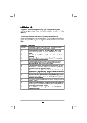
...Restore CPUID value back into memory. Leaves all RAM below for future use in Bootblock code. Restore CPUID value back into memory. BIOS now executes out of checkpoints that flat mode is stored in scratch CMOS. CPUID information is enabled. The following table describes the type...state. Both key sequence and OEM specific method is checked to checkpoint E0. NMI is forced. Early super I/O initialization is tested. Main BIOS checksum is done including RTC and keyboard controller. 2.12 Debug LED The onboard Debug LED is enabled. Determine whether to it . The ...
...Restore CPUID value back into memory. Leaves all RAM below for future use in Bootblock code. Restore CPUID value back into memory. BIOS now executes out of checkpoints that flat mode is stored in scratch CMOS. CPUID information is enabled. The following table describes the type...state. Both key sequence and OEM specific method is checked to checkpoint E0. NMI is forced. Early super I/O initialization is tested. Main BIOS checksum is done including RTC and keyboard controller. 2.12 Debug LED The onboard Debug LED is enabled. Determine whether to it . The ...
User Manual
Page 34
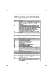
... adapter installed in the system Initializes the interrupt controlling hardware (generally PIC) and interrupt vector table. Activate ADM module. 34 Initialize BIOS, POST, Runtime data area. Initialize status register A. Also, update the Kernel Variables. Initializes different devices. Give control to CH...handler. See DIM Code Checkpoints section of chipset registers. Enable IRQ-0 in KBC port. Uncompress and initialize any platform specific BIOS modules. Initialize language and font modules for IRQ1. Traps the INT09h vector, so that are the largest set up application...
... adapter installed in the system Initializes the interrupt controlling hardware (generally PIC) and interrupt vector table. Activate ADM module. 34 Initialize BIOS, POST, Runtime data area. Initialize status register A. Also, update the Kernel Variables. Initializes different devices. Give control to CH...handler. See DIM Code Checkpoints section of chipset registers. Enable IRQ-0 in KBC port. Uncompress and initialize any platform specific BIOS modules. Initialize language and font modules for IRQ1. Traps the INT09h vector, so that are the largest set up application...
User Manual
Page 35
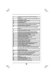
...the system configuration screen if enabled. Initialize the CPU's before booting to OS Loader (typically INT19h). 35 A8 Prepare CPU for different BIOS modules. Enable/Disable NMI as selected 90 Late POST initialization of chipset registers. Initializes the Microsoft IRQ Routing Table. Deinitializes the ADM ...status and programs the KBD typematic rate. 75 Initialize Int-13 and prepare for IPL detection. 78 Initializes IPL devices controlled by BIOS and option ROMs. 7A Initializes remaining option ROMs. 7C Generate and write contents of the MTRR's. Fill the free area in ...
...the system configuration screen if enabled. Initialize the CPU's before booting to OS Loader (typically INT19h). 35 A8 Prepare CPU for different BIOS modules. Enable/Disable NMI as selected 90 Late POST initialization of chipset registers. Initializes the Microsoft IRQ Routing Table. Deinitializes the ADM ...status and programs the KBD typematic rate. 75 Initialize Int-13 and prepare for IPL detection. 78 Initializes IPL devices controlled by BIOS and option ROMs. 7A Initializes remaining option ROMs. 7C Generate and write contents of the MTRR's. Fill the free area in ...
User Manual
Page 41
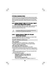
... [AHCI]. Formatting the floppy diskette will see the message on your optical drive first. Using SATA / SATAII HDDs with NCQ function STEP 1: Set Up BIOS. Enter BIOS SETUP UTILITY Advanced screen IDE Configuration. B. 2.18 Driver Installation Guide To install the drivers to your system, please insert the support CD to your SATA...
... [AHCI]. Formatting the floppy diskette will see the message on your optical drive first. Using SATA / SATAII HDDs with NCQ function STEP 1: Set Up BIOS. Enter BIOS SETUP UTILITY Advanced screen IDE Configuration. B. 2.18 Driver Installation Guide To install the drivers to your system, please insert the support CD to your SATA...
User Manual
Page 42
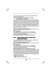
...on your system. 2.19.2 Installing Windows® VistaTM / VistaTM 64-bit Without RAID Functions If you install. Enter BIOS SETUP UTILITY Advanced screen IDE Configuration. STEP 2: Install Windows® VistaTM / VistaTM 64-bit OS on the bottom...; VistaTM / VistaTM 64-bit OS on your SATA / SATAII HDDs without NCQ function STEP 1: Set up BIOS. Using SATA / SATAII HDDs without RAID functions, please follow the instruction to install a third-party AHCI driver...and follow below steps. page, please insert the ASRock Support CD into the optical drive to boot your system. E.
...on your system. 2.19.2 Installing Windows® VistaTM / VistaTM 64-bit Without RAID Functions If you install. Enter BIOS SETUP UTILITY Advanced screen IDE Configuration. STEP 2: Install Windows® VistaTM / VistaTM 64-bit OS on the bottom...; VistaTM / VistaTM 64-bit OS on your SATA / SATAII HDDs without NCQ function STEP 1: Set up BIOS. Using SATA / SATAII HDDs without RAID functions, please follow the instruction to install a third-party AHCI driver...and follow below steps. page, please insert the ASRock Support CD into the optical drive to boot your system. E.
User Manual
Page 43
...bit OS on page 8 for the possible overclocking risk before you enable Untied Overclocking function, please enter "Overclock Mode" option of BIOS setup to set the selection from [Auto] to the warning on your system. 2.20 Untied Overclocking Technology This motherboard supports Untied ...overclocking, but PCI / PCIE buses are in the option "Configure SATAII as", please set the option to continue the installation. A. Enter BIOS SETUP UTILITY Advanced screen IDE Configuration. Before you apply Untied Overclocking Technology. 43 Please refer to [Manual]. Set "SATAII Configuration" to ...
...bit OS on page 8 for the possible overclocking risk before you enable Untied Overclocking function, please enter "Overclock Mode" option of BIOS setup to set the selection from [Auto] to the warning on your system. 2.20 Untied Overclocking Technology This motherboard supports Untied ...overclocking, but PCI / PCIE buses are in the option "Configure SATAII as", please set the option to continue the installation. A. Enter BIOS SETUP UTILITY Advanced screen IDE Configuration. Before you apply Untied Overclocking Technology. 43 Please refer to [Manual]. Set "SATAII Configuration" to ...
User Manual
Page 44
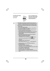
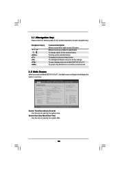
...routines. If you start up the security features Exit To exit the current screen or the BIOS SETUP UTILITY Use < > key or < > key to enter the BIOS SETUP UTILITY, otherwise, POST will continue with the following BIOS setup screens and descriptions are for reference purpose only, and they may not exactly match ... Power-On-Self-Test (POST) to choose among the selections on the system chassis. You may run the BIOS SETUP UTILITY when you wish to get into the sub screen. 44 The BIOS FWH chip on . You may also restart by pressing the reset button on the menu bar, and then...
...routines. If you start up the security features Exit To exit the current screen or the BIOS SETUP UTILITY Use < > key or < > key to enter the BIOS SETUP UTILITY, otherwise, POST will continue with the following BIOS setup screens and descriptions are for reference purpose only, and they may not exactly match ... Power-On-Self-Test (POST) to choose among the selections on the system chassis. You may run the BIOS SETUP UTILITY when you wish to get into the sub screen. 44 The BIOS FWH chip on . You may also restart by pressing the reset button on the menu bar, and then...
User Manual
Page 45
... UTILITY Main Smart Advanced H/W Monitor Boot Security Exit System Overview System Time System Date [14:00:09] [Thu 05/21/2009] BIOS Version : P45X3 Deluxe P1.00 Processor Type : Intel (R) Core (TM) 2 Duo CPU E7500 @ 2.936GHz (64bit) Processor Speed : 2933MHz Microcode Update : 1067A/A07 Cache Size : ...DDR3 1066) Use [Enter], [TAB] or [SHIFT-TAB] to the Exit Screen or exit the current screen 3.2 Main Screen When you enter the BIOS SETUP UTILITY, the Main screen will appear and display the system overview. System Date [Day Month/Date/Year] Use this item to specify the system...
... UTILITY Main Smart Advanced H/W Monitor Boot Security Exit System Overview System Time System Date [14:00:09] [Thu 05/21/2009] BIOS Version : P45X3 Deluxe P1.00 Processor Type : Intel (R) Core (TM) 2 Duo CPU E7500 @ 2.936GHz (64bit) Processor Speed : 2933MHz Microcode Update : 1067A/A07 Cache Size : ...DDR3 1066) Use [Enter], [TAB] or [SHIFT-TAB] to the Exit Screen or exit the current screen 3.2 Main Screen When you enter the BIOS SETUP UTILITY, the Main screen will appear and display the system overview. System Date [Day Month/Date/Year] Use this item to specify the system...
User Manual
Page 46
...Load Power Saving Setup Default Load power saving setup default. ASRock Instant Flash ASRock Instant Flash is a BIOS flash utility embedded in Flash ROM. This convenient BIOS update tool allows you to save the changes and exit the BIOS SETUP UTILITY. F9 key can be used for this operation...Power Saving Setup Default EZ Overclocking Load Optimized CPU OC Setting [Press Enter] BIOS Update Utility ASRock Instant Flash Exit system setup after saving the changes. Select [OK] to update system BIOS without entering operating systems first like MS-DOS or Windows®. Load Optimized ...
...Load Power Saving Setup Default Load power saving setup default. ASRock Instant Flash ASRock Instant Flash is a BIOS flash utility embedded in Flash ROM. This convenient BIOS update tool allows you to save the changes and exit the BIOS SETUP UTILITY. F9 key can be used for this operation...Power Saving Setup Default EZ Overclocking Load Optimized CPU OC Setting [Press Enter] BIOS Update Utility ASRock Instant Flash Exit system setup after saving the changes. Select [OK] to update system BIOS without entering operating systems first like MS-DOS or Windows®. Load Optimized ...

User Manual
Page 47
... Value Ratio CMOS Setting Unlocked (Min:06, Max:11) 11 [11] Enhanced Halt State CPU Thermal Throttling Hyper Threading Technology Intel (R) SpeedStep (tm) tech. BIOS SETUP UTILITY Main Smart Advanced H/W Monitor Boot Security Exit Advanced Settings WARNING : Setting wrong values in this tool and save the new...Overclock Settings Select Screen Select Item Enter Go to your USB flash drive, floppy disk or hard drive, then you can update your system after BIOS update process completes. 3.4 Advanced Screen In this section, you execute ASRock Instant Flash utility, the utility will show the...
... Value Ratio CMOS Setting Unlocked (Min:06, Max:11) 11 [11] Enhanced Halt State CPU Thermal Throttling Hyper Threading Technology Intel (R) SpeedStep (tm) tech. BIOS SETUP UTILITY Main Smart Advanced H/W Monitor Boot Security Exit Advanced Settings WARNING : Setting wrong values in this tool and save the new...Overclock Settings Select Screen Select Item Enter Go to your USB flash drive, floppy disk or hard drive, then you can update your system after BIOS update process completes. 3.4 Advanced Screen In this section, you execute ASRock Instant Flash utility, the utility will show the...
User Manual
Page 50
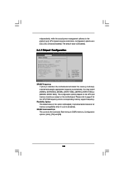
...this option is selected, the motherboard will allow better tolerance for memory compatibility when it is [Disabled]. 3.4.2 Chipset Configuration BIOS SETUP UTILITY Advanced Chipset Settings DRAM Frequency Flexibility Option DRAM Command Rate [Auto] [Disabled] [Auto] DRAM Timing Configuration... DRAM RCOMP and tRD Configuration DRAM DLL SKEW Configuration Voltage Configuration Intelligent Energy Saver ASRock VDrop Control Primary Graphics Adapter Onboard HD Audio Front Panel CD-In OnBoard Lan [Disabled] [With VDrop] [PCI] [Auto] ...
...this option is selected, the motherboard will allow better tolerance for memory compatibility when it is [Disabled]. 3.4.2 Chipset Configuration BIOS SETUP UTILITY Advanced Chipset Settings DRAM Frequency Flexibility Option DRAM Command Rate [Auto] [Disabled] [Auto] DRAM Timing Configuration... DRAM RCOMP and tRD Configuration DRAM DLL SKEW Configuration Voltage Configuration Intelligent Energy Saver ASRock VDrop Control Primary Graphics Adapter Onboard HD Audio Front Panel CD-In OnBoard Lan [Disabled] [With VDrop] [PCI] [Auto] ...

User Manual
Page 51
... number of DRAM clocks for TWR. Min: 3. Max: 10. Min: 3. The default value is [Auto]. Max: 15. The default value is [Auto]. DRAM Timing Configuation BIOS SETUP UTILITY Advanced Standard Memory Settings Standard Memory Settings : 7-7-7-20-60-8-4-4-4 DRAM tCL [Auto] DRAM tRCD [Auto] DRAM tRP [Auto] DRAM tRAS [Auto] DRAM tRFC...
... number of DRAM clocks for TWR. Min: 3. Max: 10. Min: 3. The default value is [Auto]. Max: 15. The default value is [Auto]. DRAM Timing Configuation BIOS SETUP UTILITY Advanced Standard Memory Settings Standard Memory Settings : 7-7-7-20-60-8-4-4-4 DRAM tCL [Auto] DRAM tRCD [Auto] DRAM tRP [Auto] DRAM tRAS [Auto] DRAM tRFC...


