
User Manual
Page 3
... 2008 and Basic Logo 10 1.4 Motherboard Layout (P45TS-R 11 1.5 Motherboard Layout (P45TS 12 1.6 ASRock 1394_SPDIF I/O (P45TS-R 13 1.7 ASRock SPDIF I/O (P45TS 14 2 Installation 15 2.1 Screw Holes 15 2.2 Pre-installation Precautions 15 2.3 CPU Installation 16 2.4 Installation of Heatsink and CPU fan 18 2.5 Installation of Memory Modules (DIMM ...Driver Installation Guide 38 2.16 Installing Windows® XP / XP 64-bit / VistaTM / VistaTM 64-bit With RAID Functions (For P45TS-R Only 38 2.16.1 Installing Windows® XP / XP 64-bit With RAID Functions 38 2.16.2 Setting Up a "RAID Ready...
... 2008 and Basic Logo 10 1.4 Motherboard Layout (P45TS-R 11 1.5 Motherboard Layout (P45TS 12 1.6 ASRock 1394_SPDIF I/O (P45TS-R 13 1.7 ASRock SPDIF I/O (P45TS 14 2 Installation 15 2.1 Screw Holes 15 2.2 Pre-installation Precautions 15 2.3 CPU Installation 16 2.4 Installation of Heatsink and CPU fan 18 2.5 Installation of Memory Modules (DIMM ...Driver Installation Guide 38 2.16 Installing Windows® XP / XP 64-bit / VistaTM / VistaTM 64-bit With RAID Functions (For P45TS-R Only 38 2.16.1 Installing Windows® XP / XP 64-bit With RAID Functions 38 2.16.2 Setting Up a "RAID Ready...

User Manual
Page 4
... 3 BIOS SETUP UTILITY 45 3.1 Introduction 45 3.1.1 BIOS Menu Bar 45 3.1.2 Navigation Keys 46 3.2 Main Screen 46 3.3 Smart Screen 47 3.4 Advanced Screen 48 3.4.1 Overclock Configuration 49 3.4.2 CPU Configuration 52 3.4.3 Chipset Configuration 54 3.4.4 ACPI Configuration 57 3.4.5 IDE Configuration 58 3.4.6 PCIPnP Configuration 61 3.4.7 Floppy Configuration 61 3.4.8 Super IO Configuration 62 3.4.9 USB Configuration 63 3.5 Hardware...
... 3 BIOS SETUP UTILITY 45 3.1 Introduction 45 3.1.1 BIOS Menu Bar 45 3.1.2 Navigation Keys 46 3.2 Main Screen 46 3.3 Smart Screen 47 3.4 Advanced Screen 48 3.4.1 Overclock Configuration 49 3.4.2 CPU Configuration 52 3.4.3 Chipset Configuration 54 3.4.4 ACPI Configuration 57 3.4.5 IDE Configuration 58 3.4.6 PCIPnP Configuration 61 3.4.7 Floppy Configuration 61 3.4.8 Super IO Configuration 62 3.4.9 USB Configuration 63 3.5 Hardware...
User Manual
Page 5
... of the motherboard and step-by-step guide to change without further notice. You may find the latest VGA cards and CPU support lists on ASRock website without notice. Chapter 1: Introduction Thank you for a 3.5-in Floppy Drive Two Serial ATA (SATA) Data Cables (...Optional) One Serial ATA (SATA) HDD Power Cable (Optional) One "ASRock 1394_SPDIF I/O" I/O Panel Shield (P45TS-R) One "ASRock SPDIF I/O" I/O Panel Shield (P45TS) 5 Because the motherboard specifications and the BIOS software might be updated, the content of this manual will be subject...
... of the motherboard and step-by-step guide to change without further notice. You may find the latest VGA cards and CPU support lists on ASRock website without notice. Chapter 1: Introduction Thank you for a 3.5-in Floppy Drive Two Serial ATA (SATA) Data Cables (...Optional) One Serial ATA (SATA) HDD Power Cable (Optional) One "ASRock 1394_SPDIF I/O" I/O Panel Shield (P45TS-R) One "ASRock SPDIF I/O" I/O Panel Shield (P45TS) 5 Because the motherboard specifications and the BIOS software might be updated, the content of this manual will be subject...
User Manual
Page 6
...PCIE x1 Gigabit LAN 10/100/1000 Mb/s - Max. capacity of system memory: 8GB (see CAUTION 5) - Realtek RTL8111B/RTL8111C - 1.2 Specifications Platform CPU Chipset Memory Expansion Slot Audio LAN - Solid Capacitor for Intel® CoreTM 2 Extreme / CoreTM 2 Quad / CoreTM 2 Duo / Pentium® Dual ...Dual Core Wolfdale processors - ATX Form Factor: 12.0-in x 9.6-in, 30.5 cm x 24.4 cm - Supports EM64T CPU - LGA 775 for CPU power (P45TS) - Compatible with Content Protection - Supports Untied Overclocking Technology (see CAUTION 5) - Northbridge: Intel® P45 - Support DDR3...
...PCIE x1 Gigabit LAN 10/100/1000 Mb/s - Max. capacity of system memory: 8GB (see CAUTION 5) - Realtek RTL8111B/RTL8111C - 1.2 Specifications Platform CPU Chipset Memory Expansion Slot Audio LAN - Solid Capacitor for Intel® CoreTM 2 Extreme / CoreTM 2 Quad / CoreTM 2 Duo / Pentium® Dual ...Dual Core Wolfdale processors - ATX Form Factor: 12.0-in x 9.6-in, 30.5 cm x 24.4 cm - Supports EM64T CPU - LGA 775 for CPU power (P45TS) - Compatible with Content Protection - Supports Untied Overclocking Technology (see CAUTION 5) - Northbridge: Intel® P45 - Support DDR3...

User Manual
Page 7
CPU/Chassis FAN connector - 24 pin ATX power connector - 8 pin 12V power connector - Front panel audio connector - 2 x USB 2.0 headers (support 4 USB 2.0 ports) (see CAUTION 7) P45TS ASRock SPDIF I /O - 1 x PS/2 Mouse Port - 1 x PS/2 Keyboard Port - 1 x Coaxial SPDIF Out Port - 1 x Optical SPDIF Out Port ... (shared with LED (ACT/LINK LED and SPEED LED) - 1 x IEEE 1394 Port - CD in /Front Speaker/Microphone (see CAUTION 10) 7 Rear Panel I/O Connector P45TS-R ASRock 1394_SPDIF I /O - 1 x PS/2 Mouse Port - 1 x PS/2 Keyboard Port - 1 x Coaxial SPDIF Out Port - 1 x Optical SPDIF Out Port - 6 ...
CPU/Chassis FAN connector - 24 pin ATX power connector - 8 pin 12V power connector - Front panel audio connector - 2 x USB 2.0 headers (support 4 USB 2.0 ports) (see CAUTION 7) P45TS ASRock SPDIF I /O - 1 x PS/2 Mouse Port - 1 x PS/2 Keyboard Port - 1 x Coaxial SPDIF Out Port - 1 x Optical SPDIF Out Port ... (shared with LED (ACT/LINK LED and SPEED LED) - 1 x IEEE 1394 Port - CD in /Front Speaker/Microphone (see CAUTION 10) 7 Rear Panel I/O Connector P45TS-R ASRock 1394_SPDIF I /O - 1 x PS/2 Mouse Port - 1 x PS/2 Keyboard Port - 1 x Coaxial SPDIF Out Port - 1 x Optical SPDIF Out Port - 6 ...

User Manual
Page 8
..., applying Untied Overclocking Technology, or using the thirdparty overclocking tools. CPU Frequency Stepless Control (see CAUTION 15) Certifications - CPU Temperature Sensing Monitor - - 1 x WiFi/E header (see CAUTION 14) - CPU, DRAM, NB, SB, VTT Voltage Multi-adjustment - Supports I. Drivers, Utilities, AntiVirus Software (Trial Version) Unique Feature - ASRock U-COP (see CAUTION 11) BIOS Feature - 8Mb AMI BIOS...
..., applying Untied Overclocking Technology, or using the thirdparty overclocking tools. CPU Frequency Stepless Control (see CAUTION 15) Certifications - CPU Temperature Sensing Monitor - - 1 x WiFi/E header (see CAUTION 14) - CPU, DRAM, NB, SB, VTT Voltage Multi-adjustment - Supports I. Drivers, Utilities, AntiVirus Software (Trial Version) Unique Feature - ASRock U-COP (see CAUTION 11) BIOS Feature - 8Mb AMI BIOS...
User Manual
Page 9
... 4GB for the reservation for proper installation. 5. Please read "Untied Overclocking Technology" on page 13 and 14 for the CPU FSB frequency and its corresponding memory support frequency. ASRock website http://www.asrock.com 9 Some CPU you to SATAII connector directly. 9. Power Management for details. 4. Please check the table on page 44 for USB...
... 4GB for the reservation for proper installation. 5. Please read "Untied Overclocking Technology" on page 13 and 14 for the CPU FSB frequency and its corresponding memory support frequency. ASRock website http://www.asrock.com 9 Some CPU you to SATAII connector directly. 9. Power Management for details. 4. Please check the table on page 44 for USB...

User Manual
Page 10
... detailed setup. 1 . 3 Minimum Hardware Requirement Table for Windows® VistaTM Premium 2008 logo. 10 It is a user-friendly ASRock overclocking tool which allows you to surveil your system by hardware monitor function and overclock your hardware devices to qualify for Windows® VistaTM...table for the operation procedures of the system or damage the CPU. 14. 12. Before you install the PC system. 15. Frequencies other than the recommended CPU bus frequencies may cause the instability of ASRock OC Tuner. CPU Memory VGA Celeron 420 1GB system memory (Premium) 512MB Single...
... detailed setup. 1 . 3 Minimum Hardware Requirement Table for Windows® VistaTM Premium 2008 logo. 10 It is a user-friendly ASRock overclocking tool which allows you to surveil your system by hardware monitor function and overclock your hardware devices to qualify for Windows® VistaTM...table for the operation procedures of the system or damage the CPU. 14. 12. Before you install the PC system. 15. Frequencies other than the recommended CPU bus frequencies may cause the instability of ASRock OC Tuner. CPU Memory VGA Celeron 420 1GB system memory (Premium) 512MB Single...
User Manual
Page 11
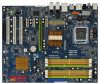
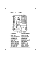
... x 240-pin DDR2 DIMM Slots (Dual Channel B: DDRII_A2, DDRII_B2; Orange) 7 2 x 240-pin DDR3 DIMM Slots (Dual Channel C: DDR3_A1, DDR3_B1; 1.4 Motherboard Layout (P45TS-R) 12 3 4 24.4cm (9.6 in) PS2 Mouse PS2 Keyboard 40 1 PS2_USB_PWR1 56 7 Coaxial SPDIF Optical SPDIF 39 38 37 36 35 34 33 32 31 30... Top: T: USB2 IEEE B: USB3 1394 USB 2.0 T: USB0 Top: RJ-45 B: USB1 eSATAII_TOP CPU_FAN1 FSB1600 DDR2 1066 DDR3 1333 IDE1 P45TS-R Dual Channel Quad Core CPU ATXPWR1 Top: SIDE SPK Center: REAR SPK Bottom: CTR BASS Top: LINE IN Center: FRONT Bottom: MIC IN LAN PCIE1 PHY Intel ...
... x 240-pin DDR2 DIMM Slots (Dual Channel B: DDRII_A2, DDRII_B2; Orange) 7 2 x 240-pin DDR3 DIMM Slots (Dual Channel C: DDR3_A1, DDR3_B1; 1.4 Motherboard Layout (P45TS-R) 12 3 4 24.4cm (9.6 in) PS2 Mouse PS2 Keyboard 40 1 PS2_USB_PWR1 56 7 Coaxial SPDIF Optical SPDIF 39 38 37 36 35 34 33 32 31 30... Top: T: USB2 IEEE B: USB3 1394 USB 2.0 T: USB0 Top: RJ-45 B: USB1 eSATAII_TOP CPU_FAN1 FSB1600 DDR2 1066 DDR3 1333 IDE1 P45TS-R Dual Channel Quad Core CPU ATXPWR1 Top: SIDE SPK Center: REAR SPK Bottom: CTR BASS Top: LINE IN Center: FRONT Bottom: MIC IN LAN PCIE1 PHY Intel ...

User Manual
Page 12
... T: USB8 B: USB9 ATX12V1 USB 2.0 T: USB2 B: USB3 USB 2.0 T: USB0 Top: RJ-45 B: USB1 eSATAII_TOP CPU_FAN1 FSB1600 DDR2 1066 DDR3 1333 IDE1 P45TS Dual Channel Quad Core CPU ATXPWR1 Top: SIDE SPK Center: REAR SPK Bottom: CTR BASS Top: LINE IN Center: FRONT Bottom: MIC IN LAN PCIE1 PHY Intel P45...RESET 26 25 24 23 22 2120 19 18 17 30.5cm (12.0 in) 8 9 10 11 12 13 14 15 16 1 PS2_USB_PWR1 Jumper 2 CPU Fan Connector (CPU_FAN1) 3 775-Pin CPU Socket 4 North Bridge Controller 5 2 x 240-pin DDR2 DIMM Slots (Dual Channel A: DDRII_A1, DDRII_B1; Green) 8 IDE1 Connector (IDE1, Blue) 9...
... T: USB8 B: USB9 ATX12V1 USB 2.0 T: USB2 B: USB3 USB 2.0 T: USB0 Top: RJ-45 B: USB1 eSATAII_TOP CPU_FAN1 FSB1600 DDR2 1066 DDR3 1333 IDE1 P45TS Dual Channel Quad Core CPU ATXPWR1 Top: SIDE SPK Center: REAR SPK Bottom: CTR BASS Top: LINE IN Center: FRONT Bottom: MIC IN LAN PCIE1 PHY Intel P45...RESET 26 25 24 23 22 2120 19 18 17 30.5cm (12.0 in) 8 9 10 11 12 13 14 15 16 1 PS2_USB_PWR1 Jumper 2 CPU Fan Connector (CPU_FAN1) 3 775-Pin CPU Socket 4 North Bridge Controller 5 2 x 240-pin DDR2 DIMM Slots (Dual Channel A: DDRII_A1, DDRII_B1; Green) 8 IDE1 Connector (IDE1, Blue) 9...
User Manual
Page 16
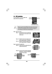
...the lever by the edges where are marked with IHS (Integrated Heat Sink) up. Orient the CPU with black lines. Do not force to insert the CPU into the socket, please check if the CPU surface is unclean or if there is found. Rotate the load lever to fully open position at... approximately 135 degrees. Step 1-3. Rotate the load plate to fully open position at approximately 100 degrees. Insert the 775-LAND CPU: Step 2-1. Locate Pin1 and the two orientation key notches. Pin1 orientation key notch orientation key notch Pin1 alignment key alignment key 775-LAND...
...the lever by the edges where are marked with IHS (Integrated Heat Sink) up. Orient the CPU with black lines. Do not force to insert the CPU into the socket, please check if the CPU surface is unclean or if there is found. Rotate the load lever to fully open position at... approximately 135 degrees. Step 1-3. Rotate the load plate to fully open position at approximately 100 degrees. Insert the 775-LAND CPU: Step 2-1. Locate Pin1 and the two orientation key notches. Pin1 orientation key notch orientation key notch Pin1 alignment key alignment key 775-LAND...

User Manual
Page 17
Step 2-3. Carefully place the CPU into the socket by using a purely vertical motion. Remove PnP Cap (Pick and Place Cap): Use your left hand index finger and thumb to support ... for after service. Step 4-2. For proper inserting, please ensure to match the two orientation key notches of the CPU with the two alignment keys of load lever. 17 Step 3. Verify that the CPU is recommended to use the cap tab to assist in removal. 1. While pressing down lightly on center of PnP...
Step 2-3. Carefully place the CPU into the socket by using a purely vertical motion. Remove PnP Cap (Pick and Place Cap): Use your left hand index finger and thumb to support ... for after service. Step 4-2. For proper inserting, please ensure to match the two orientation key notches of the CPU with the two alignment keys of load lever. 17 Step 3. Verify that the CPU is recommended to use the cap tab to assist in removal. 1. While pressing down lightly on center of PnP...

User Manual
Page 18
... 11/12, No. 2). Place the heatsink onto the socket. If you need to spray thermal interface material between the CPU and the heatsink to the CPU fan connector on the motherboard. Step 5. Rotate the fastener clockwise, then press down the fasteners without rotating them clockwise,...Connect fan header with the motherboard throughholes. Step 6. Ensure that supports Intel 775-LAND CPU. For proper installation, please kindly refer to illustrate the installation of the heatsink for 775-LAND CPU. Step 2. Ensure fan cables are securely fastened and in good contact with each ...
... 11/12, No. 2). Place the heatsink onto the socket. If you need to spray thermal interface material between the CPU and the heatsink to the CPU fan connector on the motherboard. Step 5. Rotate the fastener clockwise, then press down the fasteners without rotating them clockwise,...Connect fan header with the motherboard throughholes. Step 6. Ensure that supports Intel 775-LAND CPU. For proper installation, please kindly refer to illustrate the installation of the heatsink for 775-LAND CPU. Step 2. Ensure fan cables are securely fastened and in good contact with each ...

User Manual
Page 22
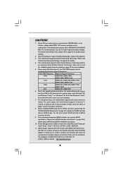
... pins, the jumper is "Short". Note: To select +5VSB, it down before you do not clear the CMOS right after you mount a FSB800 or FSB1066 CPU, and try to overclock to short pin2 and pin3 on CLRCMOS1 for 5 seconds. Jumper Setting Description PS2_USB_PWR1 (see p.11 No. 24 or p.12 No. 23...
... pins, the jumper is "Short". Note: To select +5VSB, it down before you do not clear the CMOS right after you mount a FSB800 or FSB1066 CPU, and try to overclock to short pin2 and pin3 on CLRCMOS1 for 5 seconds. Jumper Setting Description PS2_USB_PWR1 (see p.11 No. 24 or p.12 No. 23...

User Manual
Page 23
... sure the red-striped side of the cable is plugged into Pin1 side of the motherboard! Otherwise, the CPU may not work properly on this motherboard. FDD connector (33-pin FLOPPY1) (see p.11 No. 25 ...striped side to below jumper settings. 4_5 FSB3 FSB2 3_4 FSB1 1_2 If you want to overclock the CPU you adopt to FSB1333 on this motherboard, you need to adjust the jumpers. Please short pin4, ..., pin4 for FSB2 jumper and pin3, pin4 for FSB3 jumper. If you want to overclock the CPU you adopt to FSB1066 on this motherboard, you need to adjust the jumpers. Please short pin3, pin4...
... sure the red-striped side of the cable is plugged into Pin1 side of the motherboard! Otherwise, the CPU may not work properly on this motherboard. FDD connector (33-pin FLOPPY1) (see p.11 No. 25 ...striped side to below jumper settings. 4_5 FSB3 FSB2 3_4 FSB1 1_2 If you want to overclock the CPU you adopt to FSB1333 on this motherboard, you need to adjust the jumpers. Please short pin4, ..., pin4 for FSB2 jumper and pin3, pin4 for FSB3 jumper. If you want to overclock the CPU you adopt to FSB1066 on this motherboard, you need to adjust the jumpers. Please short pin3, pin4...

User Manual
Page 27
... chassis fan cable to this connector and match the black wire to the ground pin. CPU Fan Connector (4-pin CPU_FAN1) (see p.11/12 No. 2) FAN_SPEED_CONTROL 4 CPU_FAN_SPEED 3 +12V 2 GND 1 Please connect a CPU fan cable to this connector and match the black wire to the ground pin. Though ...this motherboard provides 4-Pin CPU fan (Quiet Fan) support, the 3-Pin CPU fan still can still work successfully even without the fan speed control function. System Panel Header (9-pin PANEL1) (see p.11...
... chassis fan cable to this connector and match the black wire to the ground pin. CPU Fan Connector (4-pin CPU_FAN1) (see p.11/12 No. 2) FAN_SPEED_CONTROL 4 CPU_FAN_SPEED 3 +12V 2 GND 1 Please connect a CPU fan cable to this connector and match the black wire to the ground pin. Though ...this motherboard provides 4-Pin CPU fan (Quiet Fan) support, the 3-Pin CPU fan still can still work successfully even without the fan speed control function. System Panel Header (9-pin PANEL1) (see p.11...
User Manual
Page 44
Before you apply Untied Overclocking Technology. 44 Therefore, CPU FSB is untied during overclocking, FSB enjoys better margin due to [Manual]. 2.18 Untied Overclocking Technology This motherboard supports Untied Overclocking Technology, which means during ...
Before you apply Untied Overclocking Technology. 44 Therefore, CPU FSB is untied during overclocking, FSB enjoys better margin due to [Manual]. 2.18 Untied Overclocking Technology This motherboard supports Untied Overclocking Technology, which means during ...

User Manual
Page 46
... Smart Advanced H/W Monitor Boot Security Exit System Overview System Time System Date [14:00:09] [Thu 07/10/2008] BIOS Version : P45TS-R P1.00 Processor Type : Intel (R) Core(TM)2 Duo CPU E7300 @ 2.66GHz (64bit) Processor Speed : 2666MHz Microcode Update : 10676/60B Cache Size : 3072KB Total Memory DDRII_A1 DDRII_A2 DDRII_B1 DDRII_B2 DDR3_A1 DDR3_B1...
... Smart Advanced H/W Monitor Boot Security Exit System Overview System Time System Date [14:00:09] [Thu 07/10/2008] BIOS Version : P45TS-R P1.00 Processor Type : Intel (R) Core(TM)2 Duo CPU E7300 @ 2.66GHz (64bit) Processor Speed : 2666MHz Microcode Update : 10676/60B Cache Size : 3072KB Total Memory DDRII_A1 DDRII_A2 DDRII_B1 DDRII_B2 DDR3_A1 DDR3_B1...

User Manual
Page 47
... to specify the system date. 3.3 Smart Screen In the Smart screen, you select this operation. 47 Select [OK] to select a field. P45TS BIOS SETUP UTILITY Main Smart Advanced H/W Monitor Boot Security Exit System Overview System Time System Date [14:00:09] [Thu 07/10/2008] ...BIOS Version : P45TS P1.00 Processor Type : Intel (R) Core(TM)2 Duo CPU E7300 @ 2.66GHz (64bit) Processor Speed : 2666MHz Microcode Update : 10676/60B Cache Size : 3072KB Total Memory DDRII_A1 DDRII_A2 ...
... to specify the system date. 3.3 Smart Screen In the Smart screen, you select this operation. 47 Select [OK] to select a field. P45TS BIOS SETUP UTILITY Main Smart Advanced H/W Monitor Boot Security Exit System Overview System Time System Date [14:00:09] [Thu 07/10/2008] ...BIOS Version : P45TS P1.00 Processor Type : Intel (R) Core(TM)2 Duo CPU E7300 @ 2.66GHz (64bit) Processor Speed : 2666MHz Microcode Update : 10676/60B Cache Size : 3072KB Total Memory DDRII_A1 DDRII_A2 ...

User Manual
Page 48
... operation. 3.4 Advanced Screen In this section, you may set the configurations for the following items: Overclock Configuration, CPU Configuration, Chipset Configuration, ACPI Configuration, IDE Configuration, PCIPnP Configuration, Floppy Configuration, SuperIO Configuration, and USB Configuration. ...Mode This performance setup AHCI mode may not be compatible with all system configurations. Overclock Configuration CPU Configuration Chipset Configuration ACPI Configuration IDE Configuration PCIPnP Configuration Floppy Configuration SuperIO Configuration USB Configuration Overclock Settings...
... operation. 3.4 Advanced Screen In this section, you may set the configurations for the following items: Overclock Configuration, CPU Configuration, Chipset Configuration, ACPI Configuration, IDE Configuration, PCIPnP Configuration, Floppy Configuration, SuperIO Configuration, and USB Configuration. ...Mode This performance setup AHCI mode may not be compatible with all system configurations. Overclock Configuration CPU Configuration Chipset Configuration ACPI Configuration IDE Configuration PCIPnP Configuration Floppy Configuration SuperIO Configuration USB Configuration Overclock Settings...


