
Quick Installation Guide
Page 1
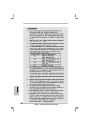
... and (2) this device must accept any means, except duplication of documentation by the California Legislature. All rights reserved. 1 ASRock P45TS-R / P45TS Motherboard English When you discard the Lithium battery in California, USA, please follow the related regulations in this guide are used...part of this installation guide may be reproduced, transcribed, transmitted, or translated in any language, in this guide. ASRock assumes no event shall ASRock, its directors, officers, employees, or agents be liable for any indirect, special, incidental, or consequential damages (...
... and (2) this device must accept any means, except duplication of documentation by the California Legislature. All rights reserved. 1 ASRock P45TS-R / P45TS Motherboard English When you discard the Lithium battery in California, USA, please follow the related regulations in this guide are used...part of this installation guide may be reproduced, transcribed, transmitted, or translated in any language, in this guide. ASRock assumes no event shall ASRock, its directors, officers, employees, or agents be liable for any indirect, special, incidental, or consequential damages (...

Quick Installation Guide
Page 2
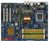
... PCI Express x1 Slot (PCIE1) 38 ATX Power Connector (ATXPWR1) 39 eSATAII Connector (eSATAII_TOP) 40 ATX 12V Connector (ATX12V1) 2 ASRock P45TS-R / P45TS Motherboard Orange) 7 2 x 240-pin DDR3 DIMM Slots (Dual Channel C: DDR3_A1, DDR3_B1; Motherboard Layout (P45TS-R) English 1 PS2_USB_PWR1 Jumper 2 CPU Fan Connector (CPU_FAN1) 3 775-Pin CPU Socket 4 North Bridge Controller 5 2 x 240-pin DDR2 DIMM...
... PCI Express x1 Slot (PCIE1) 38 ATX Power Connector (ATXPWR1) 39 eSATAII Connector (eSATAII_TOP) 40 ATX 12V Connector (ATX12V1) 2 ASRock P45TS-R / P45TS Motherboard Orange) 7 2 x 240-pin DDR3 DIMM Slots (Dual Channel C: DDR3_A1, DDR3_B1; Motherboard Layout (P45TS-R) English 1 PS2_USB_PWR1 Jumper 2 CPU Fan Connector (CPU_FAN1) 3 775-Pin CPU Socket 4 North Bridge Controller 5 2 x 240-pin DDR2 DIMM...

Quick Installation Guide
Page 3
... PCI Express x1 Slot (PCIE1) 37 ATX Power Connector (ATXPWR1) 38 eSATAII Connector (eSATAII_TOP) 39 ATX 12V Connector (ATX12V1) 3 ASRock P45TS-R / P45TS Motherboard Yellow) 6 2 x 240-pin DDR2 DIMM Slots (Dual Channel B: DDRII_A2, DDRII_B2; Motherboard Layout (P45TS) English 1 PS2_USB_PWR1 Jumper 2 CPU Fan Connector (CPU_FAN1) 3 775-Pin CPU Socket 4 North Bridge Controller 5 2 x 240-pin DDR2 DIMM...
... PCI Express x1 Slot (PCIE1) 37 ATX Power Connector (ATXPWR1) 38 eSATAII Connector (eSATAII_TOP) 39 ATX 12V Connector (ATX12V1) 3 ASRock P45TS-R / P45TS Motherboard Yellow) 6 2 x 240-pin DDR2 DIMM Slots (Dual Channel B: DDRII_A2, DDRII_B2; Motherboard Layout (P45TS) English 1 PS2_USB_PWR1 Jumper 2 CPU Fan Connector (CPU_FAN1) 3 775-Pin CPU Socket 4 North Bridge Controller 5 2 x 240-pin DDR2 DIMM...

Quick Installation Guide
Page 4
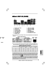
... connect a front panel audio cable to the front panel audio header. Choose "2CH", "4CH", "6CH", or "8CH" and then you use front panel audio. 4 ASRock P45TS-R / P45TS Motherboard English ASRock 1394_SPDIF I/O (P45TS-R) 1 PS/2 Mouse Port (Green) 2 IEEE 1394 Port * 3 LAN RJ-45 Port 4 Side Speaker (Gray) 5 Rear Speaker (Black) 6 Central / Bass (Orange) 7 Line In (Light...
... connect a front panel audio cable to the front panel audio header. Choose "2CH", "4CH", "6CH", or "8CH" and then you use front panel audio. 4 ASRock P45TS-R / P45TS Motherboard English ASRock 1394_SPDIF I/O (P45TS-R) 1 PS/2 Mouse Port (Green) 2 IEEE 1394 Port * 3 LAN RJ-45 Port 4 Side Speaker (Gray) 5 Rear Speaker (Black) 6 Central / Bass (Orange) 7 Line In (Light...
Quick Installation Guide
Page 5
... find "Mixer" tool on your computer, you need to connect a front panel audio cable to use front panel audio. 5 ASRock P45TS-R / P45TS Motherboard English Please select "Mixer ToolBox" , click "Enable playback multi-streaming", and click "ok". Status LAN Port LED Indications SPEED...LED LED Off 10Mbps connection Off No link Orange 100Mbps connection Orange Linked Green 1Gbps connection Blinking Data Activity LAN Port ** If you use. ASRock SPDIF I/O (P45TS) PEED ACT/LINK LED LED LAN Port 1 PS/2 Mouse Port (Green) * 2 LAN RJ-45 Port 3 Side Speaker (Gray) ...
... find "Mixer" tool on your computer, you need to connect a front panel audio cable to use front panel audio. 5 ASRock P45TS-R / P45TS Motherboard English Please select "Mixer ToolBox" , click "Enable playback multi-streaming", and click "ok". Status LAN Port LED Indications SPEED...LED LED Off 10Mbps connection Off No link Orange 100Mbps connection Orange Linked Green 1Gbps connection Blinking Data Activity LAN Port ** If you use. ASRock SPDIF I/O (P45TS) PEED ACT/LINK LED LED LAN Port 1 PS/2 Mouse Port (Green) * 2 LAN RJ-45 Port 3 Side Speaker (Gray) ...
Quick Installation Guide
Page 6
... x 9.6-in Floppy Drive Two Serial ATA (SATA) Data Cables (Optional) One Serial ATA (SATA) HDD Power Cable (Optional) One "ASRock 1394_SPDIF I/O" I/O Panel Shield (P45TS-R) One "ASRock SPDIF I/O" I/O Panel Shield (P45TS) 6 ASRock P45TS-R / P45TS Motherboard English ASRock website http://www.asrock.com If you require technical support related to this manual, chapter 1 and 2 contain introduction of this manual occur, the...
... x 9.6-in Floppy Drive Two Serial ATA (SATA) Data Cables (Optional) One Serial ATA (SATA) HDD Power Cable (Optional) One "ASRock 1394_SPDIF I/O" I/O Panel Shield (P45TS-R) One "ASRock SPDIF I/O" I/O Panel Shield (P45TS) 6 ASRock P45TS-R / P45TS Motherboard English ASRock website http://www.asrock.com If you require technical support related to this manual, chapter 1 and 2 contain introduction of this manual occur, the...
Quick Installation Guide
Page 7
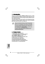
...667 non-ECC, un-buffered memory (see CAUTION 2) - Supports Hyper-Threading Technology (see CAUTION 5) - Supports Wake-On-LAN 7 ASRock P45TS-R / P45TS Motherboard English PCIE x1 Gigabit LAN 10/100/1000 Mb/s - 1.2 Specifications Platform CPU Chipset Memory Expansion Slot Audio LAN - ATX Form...: 12.0-in x 9.6-in, 30.5 cm x 24.4 cm - All Solid Capacitor design (100% Japan-made high-quality Conductive Polymer Capacitors) (P45TS-R) - Supports Untied Overclocking Technology (see CAUTION 4) - 2 x DDR3 DIMM slots - Northbridge: Intel® P45 - Dual Channel DDR3/DDR2 Memory...
...667 non-ECC, un-buffered memory (see CAUTION 2) - Supports Hyper-Threading Technology (see CAUTION 5) - Supports Wake-On-LAN 7 ASRock P45TS-R / P45TS Motherboard English PCIE x1 Gigabit LAN 10/100/1000 Mb/s - 1.2 Specifications Platform CPU Chipset Memory Expansion Slot Audio LAN - ATX Form...: 12.0-in x 9.6-in, 30.5 cm x 24.4 cm - All Solid Capacitor design (100% Japan-made high-quality Conductive Polymer Capacitors) (P45TS-R) - Supports Untied Overclocking Technology (see CAUTION 4) - 2 x DDR3 DIMM slots - Northbridge: Intel® P45 - Dual Channel DDR3/DDR2 Memory...

Quick Installation Guide
Page 8
... header - 1 x COM port header - 1 x HDMI_SPDIF header English - 1 x IEEE 1394 header (P45TS-R) - HD Audio Jack: Side Speaker/Rear Speaker/Central/Bass/ Line in/Front Speaker/Microphone (see CAUTION 7) P45TS ASRock SPDIF I /O - 1 x PS/2 Mouse Port - 1 x PS/2 Keyboard Port - 1 x Coaxial... AHCI and "Hot Plug" functions (see CAUTION 8) * RAID functions are for P45TS-R only - 1 x eSATAII 3.0Gb/s connector (shared with 1 SATAII port) (see CAUTION 10) 8 ASRock P45TS-R / P45TS Motherboard Rear Panel I/O P45TS-R ASRock 1394_SPDIF I /O - 1 x PS/2 Mouse Port - 1 x PS/2 Keyboard ...
... header - 1 x COM port header - 1 x HDMI_SPDIF header English - 1 x IEEE 1394 header (P45TS-R) - HD Audio Jack: Side Speaker/Rear Speaker/Central/Bass/ Line in/Front Speaker/Microphone (see CAUTION 7) P45TS ASRock SPDIF I /O - 1 x PS/2 Mouse Port - 1 x PS/2 Keyboard Port - 1 x Coaxial... AHCI and "Hot Plug" functions (see CAUTION 8) * RAID functions are for P45TS-R only - 1 x eSATAII 3.0Gb/s connector (shared with 1 SATAII port) (see CAUTION 10) 8 ASRock P45TS-R / P45TS Motherboard Rear Panel I/O P45TS-R ASRock 1394_SPDIF I /O - 1 x PS/2 Mouse Port - 1 x PS/2 Keyboard ...

Quick Installation Guide
Page 9
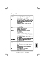
... (see CAUTION 13) - T. (Intelligent Overclocking Technology) Support CD - ACPI 1.1 Compliance Wake Up Events - Boot Failure Guard (B.F.G.) Hardware - Chassis Fan Tachometer - ASRock U-COP (see CAUTION 15) Certifications - CPU Fan Tachometer - English 9 ASRock P45TS-R / P45TS Motherboard Microsoft® Windows® 2000 / XP / XP 64-bit / VistaTM / VistaTM 64-bit compliant (see CAUTION 14) - FCC, CE, WHQL...
... (see CAUTION 13) - T. (Intelligent Overclocking Technology) Support CD - ACPI 1.1 Compliance Wake Up Events - Boot Failure Guard (B.F.G.) Hardware - Chassis Fan Tachometer - ASRock U-COP (see CAUTION 15) Certifications - CPU Fan Tachometer - English 9 ASRock P45TS-R / P45TS Motherboard Microsoft® Windows® 2000 / XP / XP 64-bit / VistaTM / VistaTM 64-bit compliant (see CAUTION 14) - FCC, CE, WHQL...
Quick Installation Guide
Page 10
... installation. 5. For audio output, this motherboard supports both stereo and mono modes. It allows you do no such limitation. 7. ASRock website http://www.asrock.com 10 ASRock P45TS-R / P45TS Motherboard English Please read "Untied Overclocking Technology" on page 25 for details about eSATAII and eSATAII installation procedures. 10. Some CPU ...64-bit CPU, there is no need to page 18 for the availability of memory modules on this motherboard. bit with ASRock WiFi-802.11g or WiFi-802.11n module, an easy-to SATAII connector, please read the installation guide of...
... installation. 5. For audio output, this motherboard supports both stereo and mono modes. It allows you do no such limitation. 7. ASRock website http://www.asrock.com 10 ASRock P45TS-R / P45TS Motherboard English Please read "Untied Overclocking Technology" on page 25 for details about eSATAII and eSATAII installation procedures. 10. Some CPU ...64-bit CPU, there is no need to page 18 for the availability of memory modules on this motherboard. bit with ASRock WiFi-802.11g or WiFi-802.11n module, an easy-to SATAII connector, please read the installation guide of...
Quick Installation Guide
Page 11
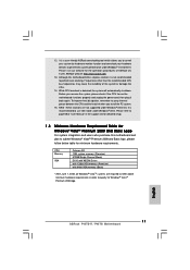
...the instability of "User Manual" in order to page 58 of the system or damage the CPU. 14. English 11 ASRock P45TS-R / P45TS Motherboard ASRock website: http://www.asrock.com 13. While CPU overheat is recommended to get the best system performance under Windows® 2000 OS. It is ... CD for detailed setup. 1.3 Minimum Hardware Requirement Table for minimum hardware requirements. 12. Please refer to qualify for the operation procedures of ASRock OC Tuner. CPU Memory VGA Celeron 420 1GB system memory (Premium) 512MB Single Channel (Basic) DX10 with WDDM Driver with 128bit VGA...
...the instability of "User Manual" in order to page 58 of the system or damage the CPU. 14. English 11 ASRock P45TS-R / P45TS Motherboard ASRock website: http://www.asrock.com 13. While CPU overheat is recommended to get the best system performance under Windows® 2000 OS. It is ... CD for detailed setup. 1.3 Minimum Hardware Requirement Table for minimum hardware requirements. 12. Please refer to qualify for the operation procedures of ASRock OC Tuner. CPU Memory VGA Celeron 420 1GB system memory (Premium) 512MB Single Channel (Basic) DX10 with WDDM Driver with 128bit VGA...
Quick Installation Guide
Page 12
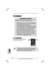
... the screw holes to secure the motherboard to do not touch the ICs. 4. Whenever you handle components. 3. 2. Otherwise, the CPU will be seriously damaged. 12 ASRock P45TS-R / P45TS Motherboard English Failure to the chassis, please do not over-tighten the screws!
... the screw holes to secure the motherboard to do not touch the ICs. 4. Whenever you handle components. 3. 2. Otherwise, the CPU will be seriously damaged. 12 ASRock P45TS-R / P45TS Motherboard English Failure to the chassis, please do not over-tighten the screws!
Quick Installation Guide
Page 13
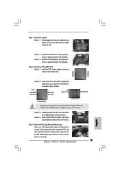
... with black lines. Step 1-2. black line black line Step 2-2. Verify that the CPU is within the socket and properly mated to assist in removal. 13 ASRock P45TS-R / P45TS Motherboard English Remove PnP Cap (Pick and Place Cap): Use your left hand index finger and thumb to support the load plate edge, engage PnP...
... with black lines. Step 1-2. black line black line Step 2-2. Verify that the CPU is within the socket and properly mated to assist in removal. 13 ASRock P45TS-R / P45TS Motherboard English Remove PnP Cap (Pick and Place Cap): Use your left hand index finger and thumb to support the load plate edge, engage PnP...
Quick Installation Guide
Page 14
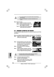
.... Secure load lever with the CPU fan connector on the motherboard (CPU_FAN1, see page 2/3, No. 2). Align fasteners with fan operation or contact other components. 14 ASRock P45TS-R / P45TS Motherboard English This cap must be secured on load plate, engage the load lever. Step 4-2. Step 4. Secure excess cable with tie-wrap to illustrate the...
.... Secure load lever with the CPU fan connector on the motherboard (CPU_FAN1, see page 2/3, No. 2). Align fasteners with fan operation or contact other components. 14 ASRock P45TS-R / P45TS Motherboard English This cap must be secured on load plate, engage the load lever. Step 4-2. Step 4. Secure excess cable with tie-wrap to illustrate the...

Quick Installation Guide
Page 15
... and DDRII_B1; For dual channel configuration, you have to the Dual Channel Memory Configuration Table below. 2.3 Installation of orange slots (DDRII_A2 and DDRII_B2). English 15 ASRock P45TS-R / P45TS Motherboard You may refer to install identical DDR2 DIMM pair in Dual Channel C (DDR3_A1 and DDR3_B1; Orange slots;
... and DDRII_B1; For dual channel configuration, you have to the Dual Channel Memory Configuration Table below. 2.3 Installation of orange slots (DDRII_A2 and DDRII_B2). English 15 ASRock P45TS-R / P45TS Motherboard You may refer to install identical DDR2 DIMM pair in Dual Channel C (DDR3_A1 and DDR3_B1; Orange slots;

Quick Installation Guide
Page 16
... fully snap back in the DDR2 DIMM slots on the slot. English The DIMM only fits in DDRII_A1 and DDRII_B2, it is properly seated. 16 ASRock P45TS-R / P45TS Motherboard DDR2 and DDR3 memory modules cannot be damaged. 5. Unlock a DIMM slot by pressing the retaining clips outward. It will cause permanent damage to disconnect...
... fully snap back in the DDR2 DIMM slots on the slot. English The DIMM only fits in DDRII_A1 and DDRII_B2, it is properly seated. 16 ASRock P45TS-R / P45TS Motherboard DDR2 and DDR3 memory modules cannot be damaged. 5. Unlock a DIMM slot by pressing the retaining clips outward. It will cause permanent damage to disconnect...
Quick Installation Guide
Page 17
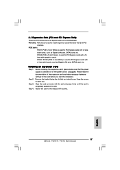
... expansion card and make sure that the power supply is switched off or the power cord is used for PCI Express cards with screws. 17 ASRock P45TS-R / P45TS Motherboard English PCI slots: PCI slots are 3 PCI slots and 4 PCI Express slots on the slot. Step 4. Remove the bracket facing the slot that you...
... expansion card and make sure that the power supply is switched off or the power cord is used for PCI Express cards with screws. 17 ASRock P45TS-R / P45TS Motherboard English PCI slots: PCI slots are 3 PCI slots and 4 PCI Express slots on the slot. Step 4. Remove the bracket facing the slot that you...

Quick Installation Guide
Page 18
... jumper cap is "Open". Note: To select +5VSB, it down before you do not clear the CMOS right after you update the BIOS. English 18 ASRock P45TS-R / P45TS Motherboard Jumper Setting Description PS2_USB_PWR1 Short pin2, pin3 to enable (see p.2/3 No. 1) +5VSB (standby) for PS/2 or USB wake up the system first, and then...
... jumper cap is "Open". Note: To select +5VSB, it down before you do not clear the CMOS right after you update the BIOS. English 18 ASRock P45TS-R / P45TS Motherboard Jumper Setting Description PS2_USB_PWR1 Short pin2, pin3 to enable (see p.2/3 No. 1) +5VSB (standby) for PS/2 or USB wake up the system first, and then...

Quick Installation Guide
Page 19
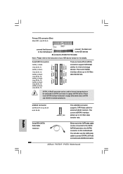
... jumper and pin3, pin4 for FSB3 jumper. Do NOT place jumper caps over the headers and connectors will cause permanent damage of the connector. 19 ASRock P45TS-R / P45TS Motherboard Placing jumper caps over these headers and connectors. FDD connector (33-pin FLOPPY1) (see p.2 No. 25 or p.3 No. 24) the red-striped side to...
... jumper and pin3, pin4 for FSB3 jumper. Do NOT place jumper caps over the headers and connectors will cause permanent damage of the connector. 19 ASRock P45TS-R / P45TS Motherboard Placing jumper caps over these headers and connectors. FDD connector (33-pin FLOPPY1) (see p.2 No. 25 or p.3 No. 24) the red-striped side to...
Quick Installation Guide
Page 20
SATAII_6 (Port5) connector can be used for internal storage device or be connected to connect SATAII_6 (Port5) connector and eSATAII connector. 20 ASRock P45TS-R / P45TS Motherboard English Serial ATAII Connectors (SATAII_1 (Port0): see p.2/3, No. 11) (SATAII_2 (Port1): see p.2/3, No. 12) (SATAII_3 (Port2): see p.2/3, No. 13) (SATAII_4 (Port3): see p.2/3, No. 14) (...
SATAII_6 (Port5) connector can be used for internal storage device or be connected to connect SATAII_6 (Port5) connector and eSATAII connector. 20 ASRock P45TS-R / P45TS Motherboard English Serial ATAII Connectors (SATAII_1 (Port0): see p.2/3, No. 11) (SATAII_2 (Port1): see p.2/3, No. 12) (SATAII_3 (Port2): see p.2/3, No. 13) (SATAII_4 (Port3): see p.2/3, No. 14) (...


