User Manual
Page 5
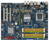
...I/O" I/O Panel Shield (P43D1600Twins-1394) One "ASRock SPDIF I/O" I/O Panel Shield (P43D1600Twins / P43Twins1600) 5 www.asrock.com/support/index.asp 1.1 Package Contents ASRock P43D1600Twins-1394 / P43D1600Twins / P43Twins1600 Motherboard (ATX Form Factor: 12.0-in x 9.6-in, 30.5 cm x 24.4 cm) ASRock P43D1600Twins-1394 / P43D1600Twins / P43Twins1600 Quick Installation Guide ASRock P43D1600Twins-1394 / P43D1600Twins / P43Twins1600 Support CD One 80-conductor Ultra ATA 66/100/133 IDE Ribbon Cable One Ribbon Cable for purchasing ASRock P43D1600Twins-1394 / P43D1600Twins / P43Twins1600 motherboard...
...I/O" I/O Panel Shield (P43D1600Twins-1394) One "ASRock SPDIF I/O" I/O Panel Shield (P43D1600Twins / P43Twins1600) 5 www.asrock.com/support/index.asp 1.1 Package Contents ASRock P43D1600Twins-1394 / P43D1600Twins / P43Twins1600 Motherboard (ATX Form Factor: 12.0-in x 9.6-in, 30.5 cm x 24.4 cm) ASRock P43D1600Twins-1394 / P43D1600Twins / P43Twins1600 Quick Installation Guide ASRock P43D1600Twins-1394 / P43D1600Twins / P43Twins1600 Support CD One 80-conductor Ultra ATA 66/100/133 IDE Ribbon Cable One Ribbon Cable for purchasing ASRock P43D1600Twins-1394 / P43D1600Twins / P43Twins1600 motherboard...
User Manual
Page 13
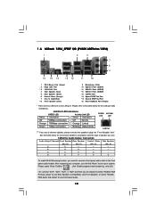
.... See the table below for connection details in accordance with the type of speaker you need to connect a front panel audio cable to the front panel audio header. Please select "Mixer ToolBox" , click "Enable playback multi-streaming", and click "ok". ...Jack". After restarting your system. Please refer to the table below for the LAN port LED indications. 1 . 6 ASRock 1394_SPDIF I/O (P43D1600Twins-1394) 1 2 3 4 7 5 8 6 9 16 15 14 13 12 11 10 1 PS/2 Mouse Port (Green) 2 IEEE 1394 Port * 3 LAN RJ-45 Port 4 Side Speaker (Gray) 5 Rear Speaker (Black) 6 Central / Bass ...
.... See the table below for connection details in accordance with the type of speaker you need to connect a front panel audio cable to the front panel audio header. Please select "Mixer ToolBox" , click "Enable playback multi-streaming", and click "ok". ...Jack". After restarting your system. Please refer to the table below for the LAN port LED indications. 1 . 6 ASRock 1394_SPDIF I/O (P43D1600Twins-1394) 1 2 3 4 7 5 8 6 9 16 15 14 13 12 11 10 1 PS/2 Mouse Port (Green) 2 IEEE 1394 Port * 3 LAN RJ-45 Port 4 Side Speaker (Gray) 5 Rear Speaker (Black) 6 Central / Bass ...

User Manual
Page 14
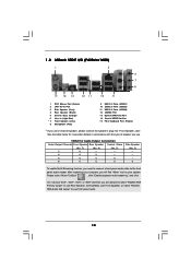
... below for connection details in accordance with the type of speaker you will find "Mixer" tool on your computer, you use. After restarting your system. 1 . 7 ASRock SPDIF I/O (P43D1600Twins) 1 2 3 6 4 7 5 8 15 14 13 12 11 10 9 1 PS/2 Mouse Port (Green) * 2 LAN RJ-45 Port 3 Side Speaker (...No. 4) (No. 5) (No. 3) 2 V -- -- -- 4 V V -- -- 6 V V V -- 8 V V V V To enable Multi-Streaming function, you need to connect a front panel audio cable to the table below for the LAN port LED indications. Please refer to the front panel audio header.
... below for connection details in accordance with the type of speaker you will find "Mixer" tool on your computer, you use. After restarting your system. 1 . 7 ASRock SPDIF I/O (P43D1600Twins) 1 2 3 6 4 7 5 8 15 14 13 12 11 10 9 1 PS/2 Mouse Port (Green) * 2 LAN RJ-45 Port 3 Side Speaker (...No. 4) (No. 5) (No. 3) 2 V -- -- -- 4 V V -- -- 6 V V V -- 8 V V V V To enable Multi-Streaming function, you need to connect a front panel audio cable to the table below for the LAN port LED indications. Please refer to the front panel audio header.
User Manual
Page 15
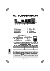
1 . 8 ASRock SPDIF I/O (P43Twins1600) 1 2 3 6 4 7 5 8 15 14 13 12 11 10 9 1 PS/2 Mouse Port (Green) 2 LAN RJ-45 Port 3 Side Speaker (Gray) 4 Rear Speaker (Black) 5 Central / Bass (Orange) 6 ... "Enable playback multi-streaming", and click "ok". TABLE for connection details in accordance with the type of speaker you need to connect a front panel audio cable to use . See the table below for Audio Output Connection Audio Output Channels Front Speaker Rear Speaker Central / Bass (No. 7) (No. 4) (No. 5) 2 V -- -- 4 V V -- 6 V V V 8 V V V Side Speaker (No...
1 . 8 ASRock SPDIF I/O (P43Twins1600) 1 2 3 6 4 7 5 8 15 14 13 12 11 10 9 1 PS/2 Mouse Port (Green) 2 LAN RJ-45 Port 3 Side Speaker (Gray) 4 Rear Speaker (Black) 5 Central / Bass (Orange) 6 ... "Enable playback multi-streaming", and click "ok". TABLE for connection details in accordance with the type of speaker you need to connect a front panel audio cable to use . See the table below for Audio Output Connection Audio Output Channels Front Speaker Rear Speaker Central / Bass (No. 7) (No. 4) (No. 5) 2 V -- -- 4 V V -- 6 V V V 8 V V V Side Speaker (No...
User Manual
Page 19
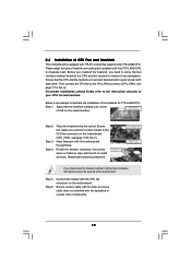
... then press down the fasteners without rotating them clockwise, the heatsink cannot be secured on the socket surface. Step 6. Step 2. Ensure fan cables are securely fastened and in good contact with fan operation or contact other . Align fasteners with Intel 775-LAND CPU to ensure... cable does not interfere with each other components. 19 Step 5. Secure excess cable with tie-wrap to dissipate heat. Below is equipped with remaining fasteners. If you need to spray ...
... then press down the fasteners without rotating them clockwise, the heatsink cannot be secured on the socket surface. Step 6. Step 2. Ensure fan cables are securely fastened and in good contact with fan operation or contact other . Align fasteners with Intel 775-LAND CPU to ensure... cable does not interfere with each other components. 19 Step 5. Secure excess cable with tie-wrap to dissipate heat. Below is equipped with remaining fasteners. If you need to spray ...
User Manual
Page 24
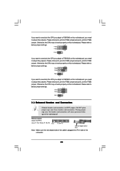
...) (see p.11 No. 25 or p.12 No. 24) Pin1 FLOPPY1 the red-striped side to Pin1 Note: Make sure the red-striped side of the cable is plugged into Pin1 side of the motherboard! Otherwise, the CPU may not work properly on this motherboard. Please short pin3, pin4 for FSB2 jumper...
...) (see p.11 No. 25 or p.12 No. 24) Pin1 FLOPPY1 the red-striped side to Pin1 Note: Make sure the red-striped side of the cable is plugged into Pin1 side of the motherboard! Otherwise, the CPU may not work properly on this motherboard. Please short pin3, pin4 for FSB2 jumper...
User Manual
Page 25
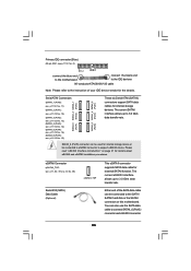
... No. 16) (SATAII_6 (Port5): see p.11, No. 39 or p.12 No. 38) Serial ATA (SATA) Data Cable (Optional) eSATAII_TOP This eSATAII connector supports SATA data cable for the details. SATAII_6 (Port5) connector can be connected to eSATAII connector to connect SATAII_6 (Port5) connector and eSATAII connector. ...of your IDE device vendor for external SATAII function. The current eSATAII interface allows up to the instruction of the SATA data cable can be used for details about eSATAII and eSATAII installation procedures. The current SATAII interface allows up to the SATA / SATAII...
... No. 16) (SATAII_6 (Port5): see p.11, No. 39 or p.12 No. 38) Serial ATA (SATA) Data Cable (Optional) eSATAII_TOP This eSATAII connector supports SATA data cable for the details. SATAII_6 (Port5) connector can be connected to eSATAII connector to connect SATAII_6 (Port5) connector and eSATAII connector. ...of your IDE device vendor for external SATAII function. The current eSATAII interface allows up to the instruction of the SATA data cable can be used for details about eSATAII and eSATAII installation procedures. The current SATAII interface allows up to the SATA / SATAII...
User Manual
Page 26
...please refer to this motherboard. Then connect the white end of SATA power cable to the power connector of SATA power cable to the power connector on this picture for ASRock DeskExpress. 26 Serial ATA (SATA) Power Cable (Optional) connect to the SATA HDD power connector connect to the power ... TXN TXP GND2 PCIE_RST# +3SVB RXN RXP 1 GND1 D0-D0+ PexCLK PexCLK# USB+5V_1 PME# This header supports WiFi+AP function with ASRock WiFi-802.11g or WiFi-802.11n module, an easy-to create a wireless environment and enjoy the convenience of wireless network connectivity. If you...
...please refer to this motherboard. Then connect the white end of SATA power cable to the power connector of SATA power cable to the power connector on this picture for ASRock DeskExpress. 26 Serial ATA (SATA) Power Cable (Optional) connect to the SATA HDD power connector connect to the power ... TXN TXP GND2 PCIE_RST# +3SVB RXN RXP 1 GND1 D0-D0+ PexCLK PexCLK# USB+5V_1 PME# This header supports WiFi+AP function with ASRock WiFi-802.11g or WiFi-802.11n module, an easy-to create a wireless environment and enjoy the convenience of wireless network connectivity. If you...
User Manual
Page 27
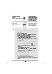
...: see p.11 No. 29 or p.12, No. 28) GND PRESENCE# MIC_RET OUT_RET 1 OUT2_L J_SENSE OUT2_R MIC2_R MIC2_L This is an interface for front panel audio cable that allows convenient connection and control of "Playback" portion. Connect Ground (GND) to the front panel audio header as below: A. Enter BIOS Setup Utility. B. Click...
...: see p.11 No. 29 or p.12, No. 28) GND PRESENCE# MIC_RET OUT_RET 1 OUT2_L J_SENSE OUT2_R MIC2_R MIC2_L This is an interface for front panel audio cable that allows convenient connection and control of "Playback" portion. Connect Ground (GND) to the front panel audio header as below: A. Enter BIOS Setup Utility. B. Click...
User Manual
Page 28
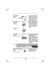
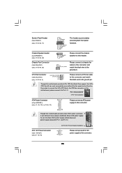
...system front panel functions. 1 SPEAKER DUMMY DUMMY +5V Please connect the chassis speaker to this header. GND +12V CHA_FAN_SPEED Please connect a chassis fan cable to this motherboard provides 4-Pin CPU fan (Quiet Fan) support, the 3-Pin CPU fan still can still work successfully even without the fan speed control... adopt a traditional 20-pin ATX power supply. ATX 12V Power Connector (8-pin ATX12V1) (see p.11/12 No. 2) GND 1 Please connect a CPU fan cable to this connector and match the black wire to the ground pin. To use the 20-pin ATX power supply, please plug your power supply...
...system front panel functions. 1 SPEAKER DUMMY DUMMY +5V Please connect the chassis speaker to this header. GND +12V CHA_FAN_SPEED Please connect a chassis fan cable to this motherboard provides 4-Pin CPU fan (Quiet Fan) support, the 3-Pin CPU fan still can still work successfully even without the fan speed control... adopt a traditional 20-pin ATX power supply. ATX 12V Power Connector (8-pin ATX12V1) (see p.11/12 No. 2) GND 1 Please connect a CPU fan cable to this connector and match the black wire to the ground pin. To use the 20-pin ATX power supply, please plug your power supply...
User Manual
Page 29
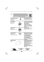
... GND blue black SPDIFOUT GND blue black SPDIFOUT GND blue black 29 white end (2-pin) C. Please connect the HDMI_SPDIF connector of HDMI_SPDIF cable to connect HDMI Digital TV/ projector/LCD devices. black end B. Then connect the white end (B or C) of HDMI VGA card ... DDTR#1 DDSR#1 CCTS#1 1 RRI#1 RRTS#1 GND TTXD1 DDCD#1 1 GND SPDIFOUT +5V HDMI_SPDIF Cable (Optional) C B A Besides one default IEEE 1394 port on the motherboard. This COM1 header supports a serial port module. IEEE 1394 Header (9-pin FRONT_1394) (see p.11 No. 23) RXTPAM_0 GND RXTPBM_0 +12V GND 1 +12V...
... GND blue black SPDIFOUT GND blue black SPDIFOUT GND blue black 29 white end (2-pin) C. Please connect the HDMI_SPDIF connector of HDMI_SPDIF cable to connect HDMI Digital TV/ projector/LCD devices. black end B. Then connect the white end (B or C) of HDMI VGA card ... DDTR#1 DDSR#1 CCTS#1 1 RRI#1 RRTS#1 GND TTXD1 DDCD#1 1 GND SPDIFOUT +5V HDMI_SPDIF Cable (Optional) C B A Besides one default IEEE 1394 port on the motherboard. This COM1 header supports a serial port module. IEEE 1394 Header (9-pin FRONT_1394) (see p.11 No. 23) RXTPAM_0 GND RXTPBM_0 +12V GND 1 +12V...
User Manual
Page 30
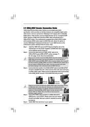
...There are two white ends (2-pin and 3-pin) on the motherboard. Step 2. Step 3. Connect the white end (B or C) of HDMI_SPDIF cable to connect HDMI Digital TV/projector/LCD devices. Otherwise, the motherboard and the VGA card may cause permanent damage to page 29. Connect the ...black end (A) of HDMI_SPDIF cable to the HDMI_SPDIF connector of the HDMI VGA card you install. Please choose the appropriate white end according to the HDMI_SPDIF header (HDMI_SPDIF1...
...There are two white ends (2-pin and 3-pin) on the motherboard. Step 2. Step 3. Connect the white end (B or C) of HDMI_SPDIF cable to connect HDMI Digital TV/projector/LCD devices. Otherwise, the motherboard and the VGA card may cause permanent damage to page 29. Connect the ...black end (A) of HDMI_SPDIF cable to the HDMI_SPDIF connector of the HDMI VGA card you install. Please choose the appropriate white end according to the HDMI_SPDIF header (HDMI_SPDIF1...

User Manual
Page 32
... eSATAII device Connect the other end of the eSATAII device cable to the eSATAII connector (eSATAII_TOP) 2. Connect the SATA data cable to the orange SATAII connector (SATAII_6 (Port5)) Connect the SATA data cable to eSATAII port of the I /O shield 32 see p.11/12 No.15) and the eSATAII connector (eSATAII_TOP; Use... the eSATAII device cable to connect the orange SATAII connector (SATAII_6 (Port5); In order to enable the eSATAII port of the I/O shield, you need to connect eSATAII ...
... eSATAII device Connect the other end of the eSATAII device cable to the eSATAII connector (eSATAII_TOP) 2. Connect the SATA data cable to the orange SATAII connector (SATAII_6 (Port5)) Connect the SATA data cable to eSATAII port of the I /O shield 32 see p.11/12 No.15) and the eSATAII connector (eSATAII_TOP; Use... the eSATAII device cable to connect the orange SATAII connector (SATAII_6 (Port5); In order to enable the eSATAII port of the I/O shield, you need to connect eSATAII ...
User Manual
Page 35
... are NOT set for RAID configuration, it cannot perform Hot Plug if the OS has been installed into the drive bays of the SATA data cable to the SATA / SATAII hard disk. eSATAII is not recommended to insert and remove the SATA / SATAII HDDs while the system is Hot Plug Function... the other end of your chassis. For example, with Hot Plug capability that enables you to the motherboard's SATAII connector. STEP 2: Connect the SATA power cable to the SATA / SATAII hard disk. This section will guide you may install SATA / SATAII hard disks on and in AHCI mode. STEP 1: Install the...
... are NOT set for RAID configuration, it cannot perform Hot Plug if the OS has been installed into the drive bays of the SATA data cable to the SATA / SATAII hard disk. eSATAII is not recommended to insert and remove the SATA / SATAII HDDs while the system is Hot Plug Function... the other end of your chassis. For example, with Hot Plug capability that enables you to the motherboard's SATAII connector. STEP 2: Connect the SATA power cable to the SATA / SATAII hard disk. This section will guide you may install SATA / SATAII hard disks on and in AHCI mode. STEP 1: Install the...
User Manual
Page 36
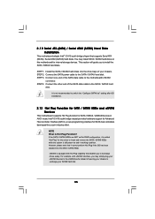
... driver is definitely not able to reduce the risk of HDD crash or data loss. 36 Make sure to power supply Caution 1. SATA data cable (Red) B. Below operation procedure is indicated in AHCI mode. Make sure your SATA / SATAII HDD can support Hot Plug function from your ...please check below operation guide of our motherboard is designed only for SATA / SATAII HDD in the product spec on our support website: www.asrock.com 4. 2.14 SATA / SATAII HDD Hot Plug Feature and Operation Guide This motherboard supports Hot Plug feature for our motherboard, which cannot support...
... driver is definitely not able to reduce the risk of HDD crash or data loss. 36 Make sure to power supply Caution 1. SATA data cable (Red) B. Below operation procedure is indicated in AHCI mode. Make sure your SATA / SATAII HDD can support Hot Plug function from your ...please check below operation guide of our motherboard is designed only for SATA / SATAII HDD in the product spec on our support website: www.asrock.com 4. 2.14 SATA / SATAII HDD Hot Plug Feature and Operation Guide This motherboard supports Hot Plug feature for our motherboard, which cannot support...

User Manual
Page 37
...-pin power connector (White) Step 3 Connect SATA 15-pin power cable connector (Black) end to the SATA / SATAII HDD. How to Hot Unplug a SATA / SATAII ... and data loss. Step 2 Unplug SATA 15-pin power cable connector (Black) from SATA / SATAII HDD side. the motherboard's SATAII connector. Step 4 Connect SATA data cable to SATA / SATAII HDD. Step 1 Unplug SATA data cable from SATA / SATAII HDD side. 37 How to Hot... the SATA / SATAII HDD damage and data loss. Step 1 Please connect SATA power cable 1x4-pin end Step 2 Connect SATA data cable to (White) to the power supply 1x4-pin...
...-pin power connector (White) Step 3 Connect SATA 15-pin power cable connector (Black) end to the SATA / SATAII HDD. How to Hot Unplug a SATA / SATAII ... and data loss. Step 2 Unplug SATA 15-pin power cable connector (Black) from SATA / SATAII HDD side. the motherboard's SATAII connector. Step 4 Connect SATA data cable to SATA / SATAII HDD. Step 1 Unplug SATA data cable from SATA / SATAII HDD side. 37 How to Hot... the SATA / SATAII HDD damage and data loss. Step 1 Please connect SATA power cable 1x4-pin end Step 2 Connect SATA data cable to (White) to the power supply 1x4-pin...
Quick Installation Guide
Page 4
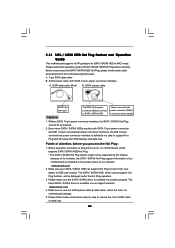
.... 5) (No. 6) (No. 4) 2 V -- -- -- 4 V V -- -- 6 V V V -- 8 V V V V To enable Multi-Streaming function, you need to connect a front panel audio cable to the table below for the LAN port LED indications. Choose "2CH", "4CH", "6CH", or "8CH" and then you use front panel audio...the table below for connection details in accordance with the type of speaker you are two LED next to the LAN port. ASRock 1394_SPDIF I/O (P43D1600Twins-1394) 1 PS/2 Mouse Port (Green) 2 IEEE 1394 Port * 3 LAN RJ-45 Port 4 Side Speaker (Gray) 5 Rear Speaker (Black) 6 Central / Bass (Orange...
.... 5) (No. 6) (No. 4) 2 V -- -- -- 4 V V -- -- 6 V V V -- 8 V V V V To enable Multi-Streaming function, you need to connect a front panel audio cable to the table below for the LAN port LED indications. Choose "2CH", "4CH", "6CH", or "8CH" and then you use front panel audio...the table below for connection details in accordance with the type of speaker you are two LED next to the LAN port. ASRock 1394_SPDIF I/O (P43D1600Twins-1394) 1 PS/2 Mouse Port (Green) 2 IEEE 1394 Port * 3 LAN RJ-45 Port 4 Side Speaker (Gray) 5 Rear Speaker (Black) 6 Central / Bass (Orange...

Quick Installation Guide
Page 5
...". Please select "Mixer ToolBox" , click "Enable playback multi-streaming", and click "ok". Please refer to use front panel audio. 5 ASRock Motherboard English See the table below for the LAN port LED indications. ASRock SPDIF I/O (P43D1600Twins) PEED ACT/LINK LED LED LAN Port 1 PS/2 Mouse Port (Green) * 2 LAN RJ-45 Port 3 Side Speaker (Gray... are two LED next to the front panel audio header. Choose "2CH", "4CH", "6CH", or "8CH" and then you need to connect a front panel audio cable to the LAN port.
...". Please select "Mixer ToolBox" , click "Enable playback multi-streaming", and click "ok". Please refer to use front panel audio. 5 ASRock Motherboard English See the table below for the LAN port LED indications. ASRock SPDIF I/O (P43D1600Twins) PEED ACT/LINK LED LED LAN Port 1 PS/2 Mouse Port (Green) * 2 LAN RJ-45 Port 3 Side Speaker (Gray... are two LED next to the front panel audio header. Choose "2CH", "4CH", "6CH", or "8CH" and then you need to connect a front panel audio cable to the LAN port.
Quick Installation Guide
Page 6
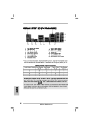
... TABLE for connection details in accordance with the type of speaker you use 2-channel speaker, please connect the speaker's plug into "Front Speaker Jack". ASRock SPDIF I/O (P43Twins1600) 1 PS/2 Mouse Port (Green) 2 LAN RJ-45 Port 3 Side Speaker (Gray) 4 Rear Speaker (Black) 5 .... 5) 2 V -- -- 4 V V -- 6 V V V 8 V V V Side Speaker (No. 3) ---V To enable Multi-Streaming function, you need to connect a front panel audio cable to use Rear Speaker, Central/Bass, and Front Speaker, or select "Realtek HDA Audio 2nd output" to the front panel audio header. Please select "Mixer...
... TABLE for connection details in accordance with the type of speaker you use 2-channel speaker, please connect the speaker's plug into "Front Speaker Jack". ASRock SPDIF I/O (P43Twins1600) 1 PS/2 Mouse Port (Green) 2 LAN RJ-45 Port 3 Side Speaker (Gray) 4 Rear Speaker (Black) 5 .... 5) 2 V -- -- 4 V V -- 6 V V V 8 V V V Side Speaker (No. 3) ---V To enable Multi-Streaming function, you need to connect a front panel audio cable to use Rear Speaker, Central/Bass, and Front Speaker, or select "Realtek HDA Audio 2nd output" to the front panel audio header. Please select "Mixer...
Quick Installation Guide
Page 7
.../index.asp 1.1 Package Contents ASRock P43D1600Twins-1394 / P43D1600Twins / P43Twins1600 Motherboard (ATX Form Factor: 12.0-in x 9.6-in Floppy Drive Four Serial ATA (SATA) Data Cables (Optional) (P43D1600Twins-1394 / P43D1600Twins) Two Serial ATA (SATA) Data Cables (Optional) (P43Twins1600) One Serial ATA (SATA) HDD Power Cable (Optional) One HDMI_SPDIF Cable (Optional) One "ASRock 1394_SPDIF I/O" I/O Panel Shield (P43D1600Twins-1394) One "ASRock SPDIF I/O" I/O Panel Shield (P43D1600Twins / P43Twins1600) 7 ASRock Motherboard English This Quick...
.../index.asp 1.1 Package Contents ASRock P43D1600Twins-1394 / P43D1600Twins / P43Twins1600 Motherboard (ATX Form Factor: 12.0-in x 9.6-in Floppy Drive Four Serial ATA (SATA) Data Cables (Optional) (P43D1600Twins-1394 / P43D1600Twins) Two Serial ATA (SATA) Data Cables (Optional) (P43Twins1600) One Serial ATA (SATA) HDD Power Cable (Optional) One HDMI_SPDIF Cable (Optional) One "ASRock 1394_SPDIF I/O" I/O Panel Shield (P43D1600Twins-1394) One "ASRock SPDIF I/O" I/O Panel Shield (P43D1600Twins / P43Twins1600) 7 ASRock Motherboard English This Quick...
